Week 4 Challenge : CFD Meshing for BMW car
-
Aim:To perform CFD meshing for the given geometrical model of the BMW car.
To check and to solve all geometrical errors on half portion and to assign appropriate PIDs.
To perform meshing with the given target length and element quality criteria.
After meshing the half model, to do symmetry to the other side.Target lengths for the different parts of a model are as follow:
- Body - 3 mm
- Lights - 4 mm
- Grills - 1 mm
- Rims and Tyres - 2 mm
- Optical Rear view mirror - 2 mm
- Window - 2 mm
- Silencer - 3 mm
- Logo - 1 mm
References for Quality Criterias are taken from the video lectures.
To mesh Wind tunnel volume with tetra elements.(Optional)
Steps for Meshing of geometric model of the BMW car:
- To refine the mesh lengths and macros of the given model.
i) The original mesh lengths of model are set to 30 mm. Thus some finer features are not captured correctly. ii) To refine the mesh lengths.Change the Mesh>Length>Perimeters to 1 mm 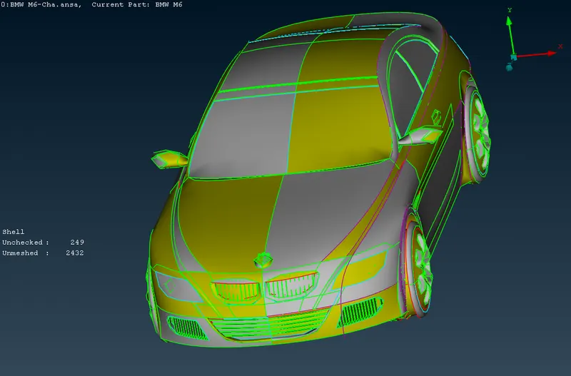
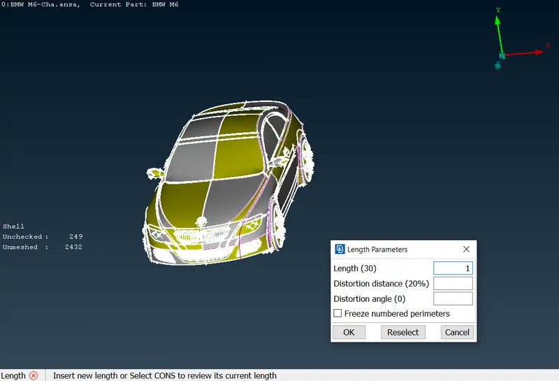
iii) To refine the mesh lengths.Change the Mesh>Length>Macros to 1 mm iv) The final refined model. The finer features similar to the one on the logo and rear view mirror are captured with accetable accuracy. 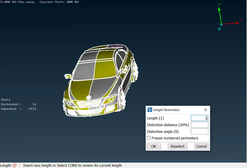
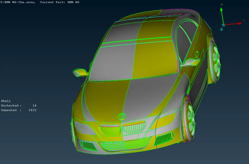
- To cut the geometric model into half for the centrally symmetric components.
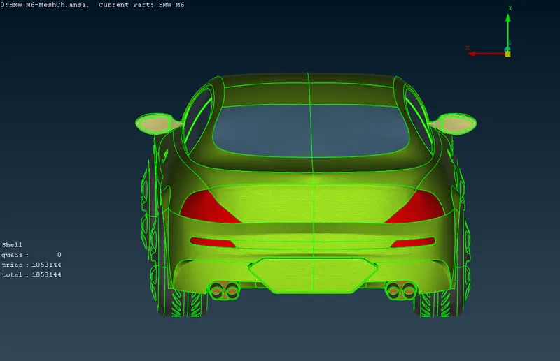
i) The original model has the central axis symmetry when looking from the front of the car. The car body, rear view mirrors, tyres , silencers, lights and grills are symmetric about central axis. ii) Thus ro reduce the efforts we will work on the half of the symmetric model. But the components like logo are assymetric about same axis will be kept as it is to work on. iii) The front view to show vertical axis symmetry. iv) The back view to show verical axis symmetry. 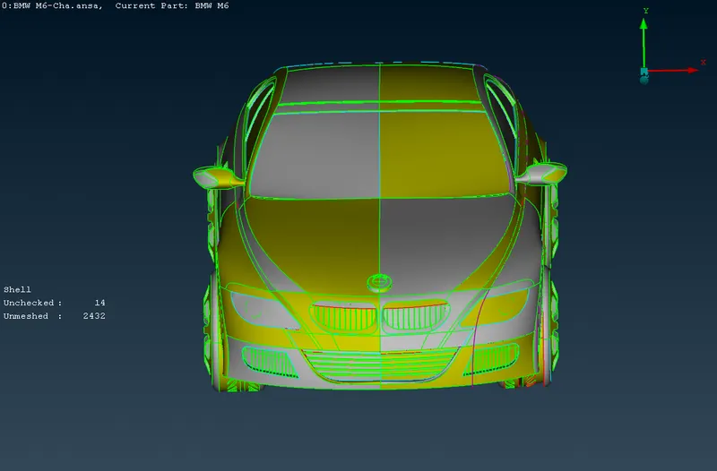
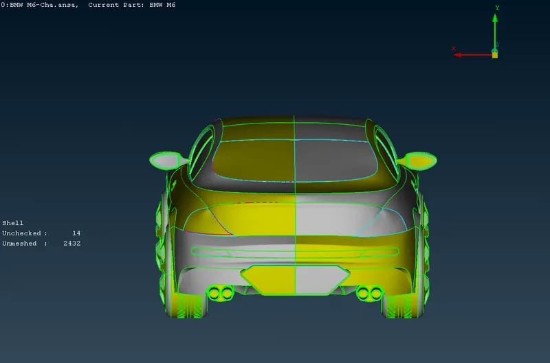
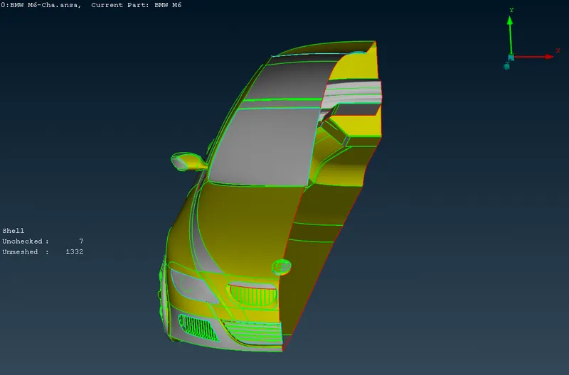
v) The view to show asymmetry of the logo about vertical axis. vi) The model after removing the symmetric half using delete command and selecting required portion of the model. 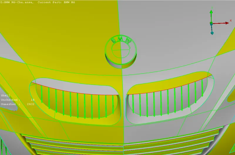
- Strategy for the geometric clean up of the whole model and list of surfaces and volumes to be retained.
i) The original model is having multiple seperate volumes and surfaces for internal features. As we are going to need the external feature for CFD study of the flow over a car in wind tunnel. ii) Thus we will make one single internal volume for car body which will be closed after the copying the symmetric part. So the components which are in direct contact with car body will be cleaned in such a way that they will become the integral part of the volume of the car body. iii) These components are the logo and rear view mirrors which will be integrated with the car body volume. Thus the surfaces of the same cleaned accordingly. Interconnecting surfaces with the cae body are deleted to make in single volume. iv) Similarly the lights, grills,windows which are having internal surfaces for internal features are cleaned such that the internal volume of the car is maintained and no extra seperate volume is created. v) The tyres and silencers are not in direct contact with car body in the model but these are required so we will keep them such that they form single separate volume. vi) The car body bottom and back surfaces are cleaned such that the original shape and borders are maintained. vii) The list of volumes to be retained. viii) Surface Meshing. - Car body internal volume with logo,grills,lights,rear view mirror and windows.
- The internal volume tyres. (4 numbers in final model)
- The internal volume of silencers. (2 numbers in final model).
The components are surface meshed as per given target lengths and quality criteria. There should not be any off element in the model. - Geometric clean up of the grills.
i) The isolated internal view for the all grills on the half model showing the internal features. ii) The isolated internal view of lower left grill showing the internal features and multiple single and triple cons. 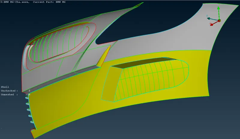
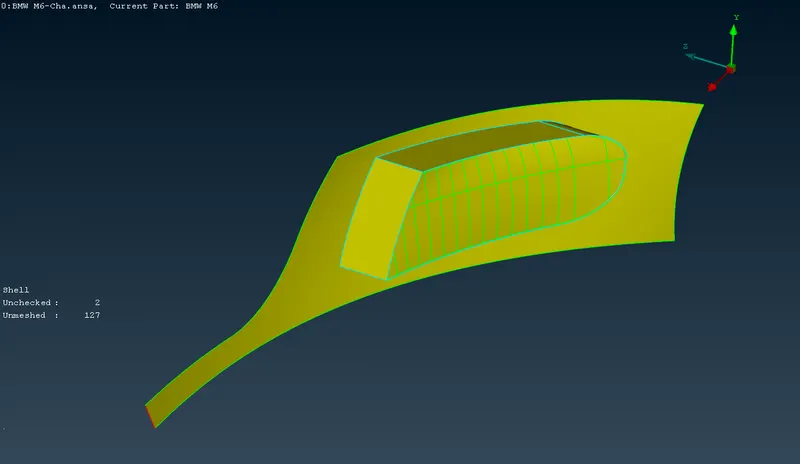
iii) The isolated external view of lower left grill showing the external features and multiple single and triple cons. iv) The lower left grills are cleaned from inside to make single volume for internal car body. Extra internal surfaces are deleted. The final internal view of the lower left grills. 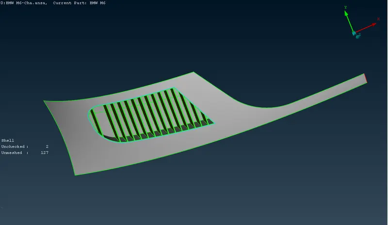
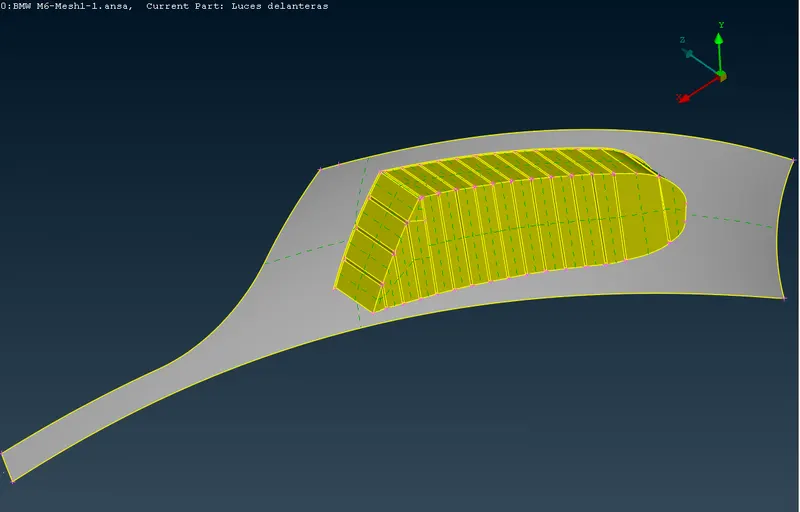
v) The isolated internal view of lower right grill showing the internal features and multiple single and triple cons. vi) The isolated external view of lower right grill showing the external features and multiple single and triple cons. 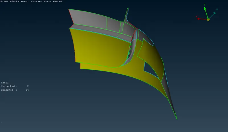
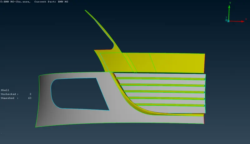
vii) The lower right grills are cleaned from inside to make single volume for internal car body. Extra internal surfaces are deleted. The final internal view of the lower right grills. viii) The isolated internal view of upper right grill showing the internal features and multiple single and triple cons. 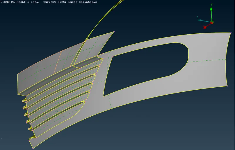
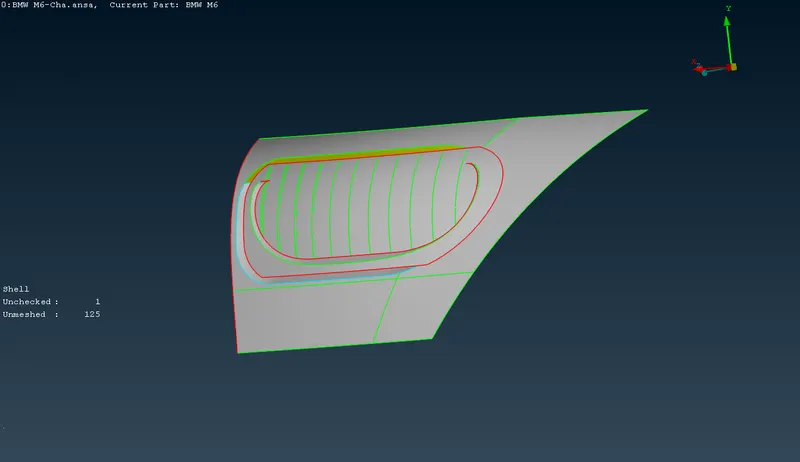
ix) The isolated external view of upper right grill showing the external features and multiple single and triple cons. x) The lower right grills are cleaned from inside to make single volume for internal car body. Extra internal surfaces are deleted. The final internal view of the lowe left grills. 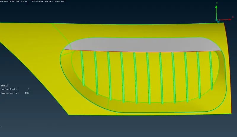
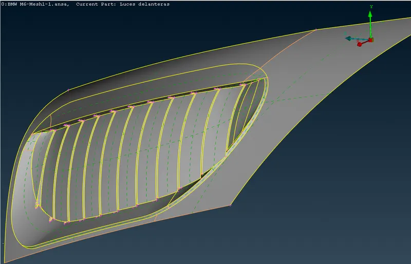
- Geometric clean up of the lights.
i) The isolated internal view of front lights showing the internal features and multiple single and triple cons. ii) The isolated external view of front lights showing the external features and multiple single and triple cons. 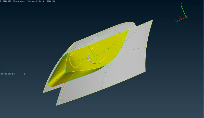
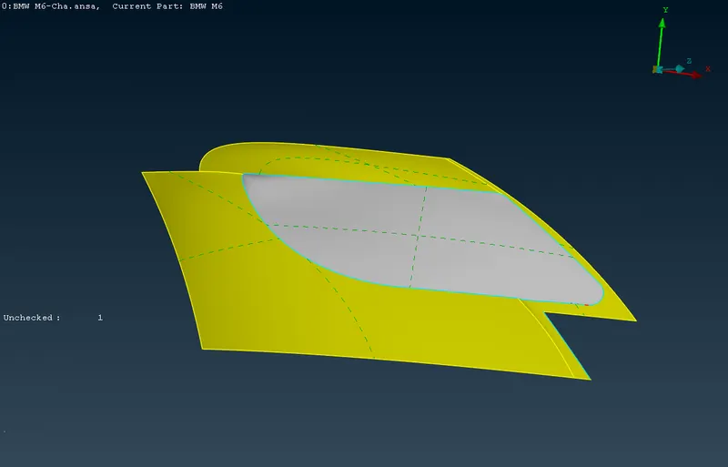
iii) The front lights are cleaned from inside to make single volume for internal car body. Extra internal surfaces are deleted. The final internal view of the front lights. iv) The isolated internal view of back lights showing the internal features and multiple single and triple cons. 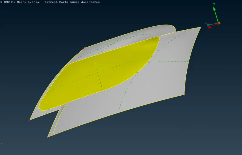
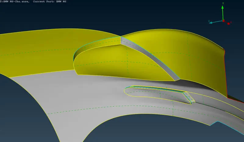
v) The isolated external view of back lights showing the external features and multiple single and triple cons. vi) The back lights are cleaned from inside to make single volume for internal car body. Extra internal surfaces are deleted. The final internal view of the back lights. 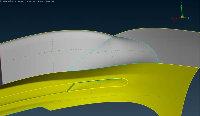
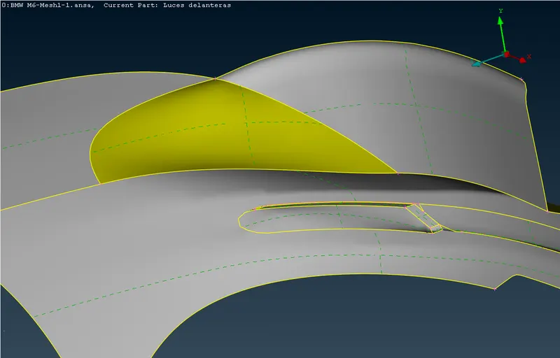
- Geometric clean up of the logo.
i) The isolated external view of logo showing the external features and multiple single and triple cons. ii) The isolated internal view of logo showing the internal features and multiple single and triple cons. 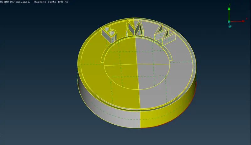
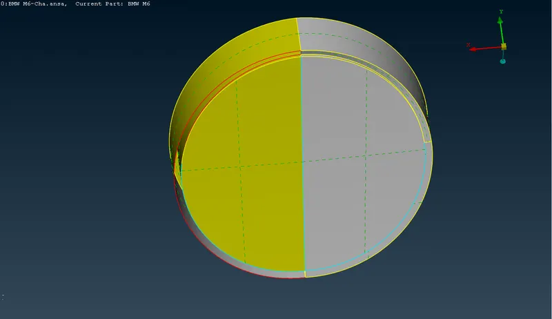
iii) Wireframe view of the logo showing internal surfaces and the multiple single and tripple cons. iv) The internal view after cleaning the multiple surfaces. 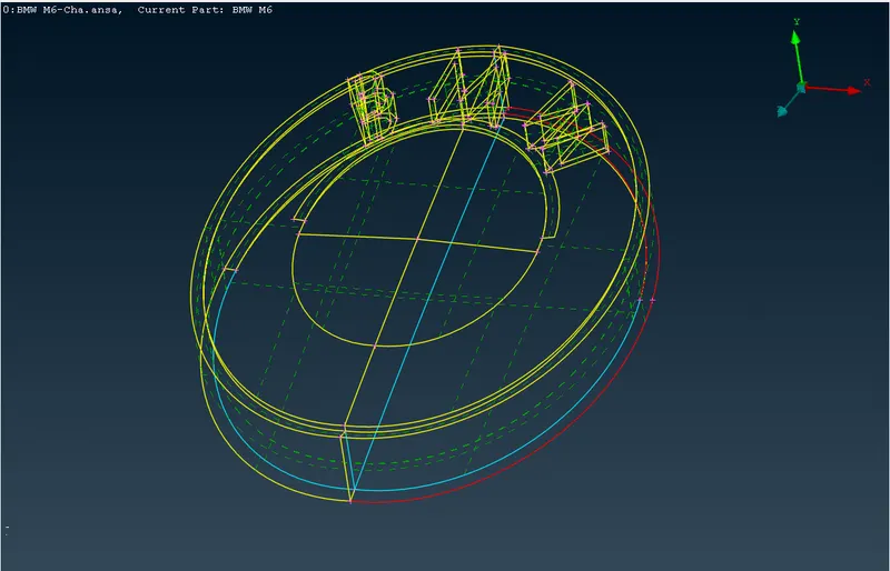
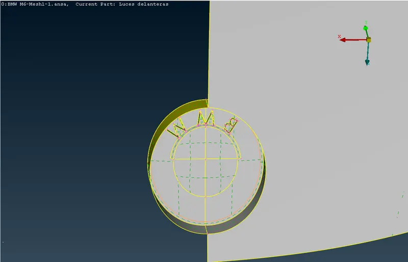
v) External view of the logo after geometric cleaning vi) Close view of the logo showing external features after geometrical cleaning. 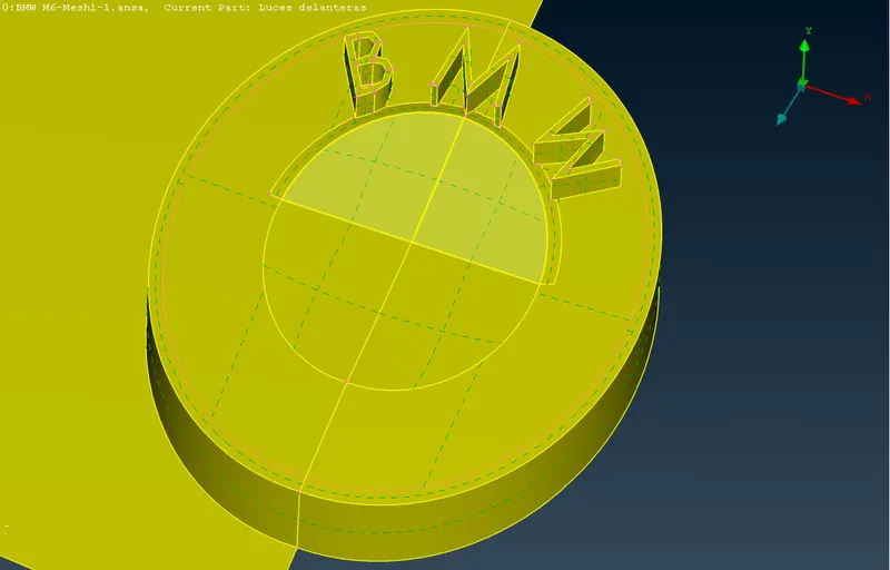
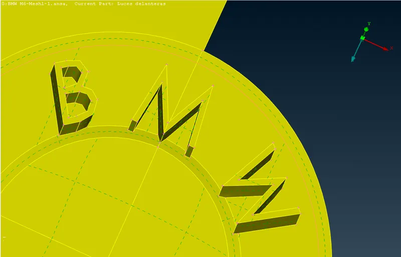
- Geometric clean up of the rear view mirror
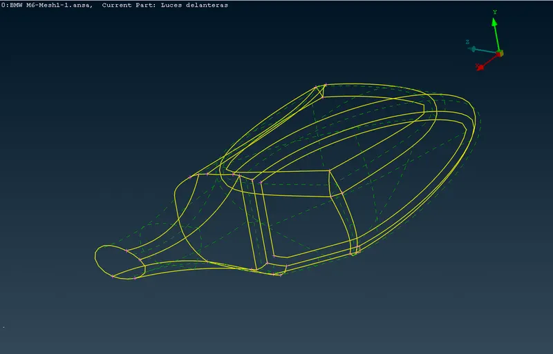
i) The isolated external view of the rear view mirror showing tripple cons ii) The isolated wireframe view of the rear view mirror showing multiple triple cons and internal surfaces. 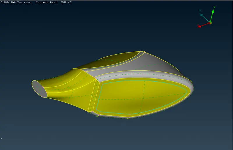
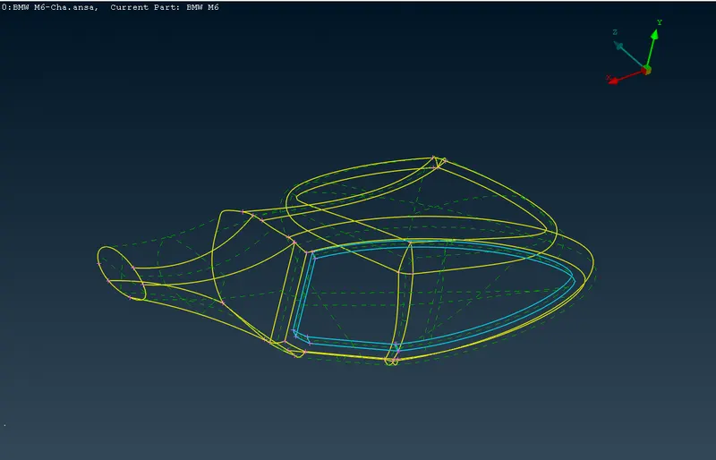
iii) The isolated external view of the rear view mirror after the geometric clean up. iv) The isolated wireframe view of the rear view mirror after geometrical clean up. 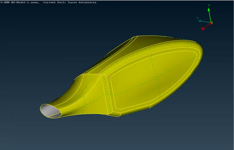
- Geometric clean up of the windows.
i) The external view of the windows showing multiple single and triple cons. ii) The isolated external view of the windows showing muliple triple cons and internal surfaces. 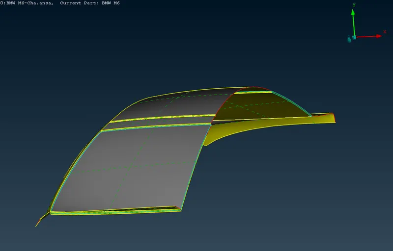
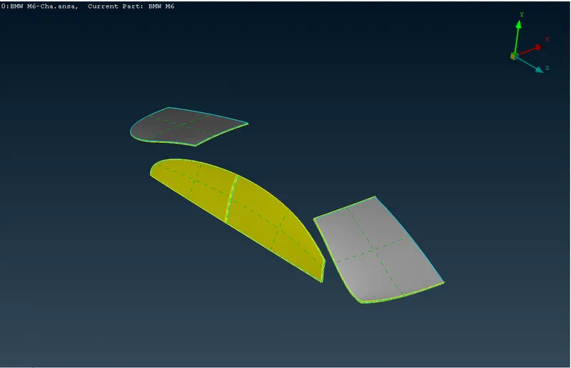
iii) The isolated wireframe view of the windows confirming multiple surfaces at the windows so the triple cons. iv) The isolated external view of the windows after the geometric clean up. 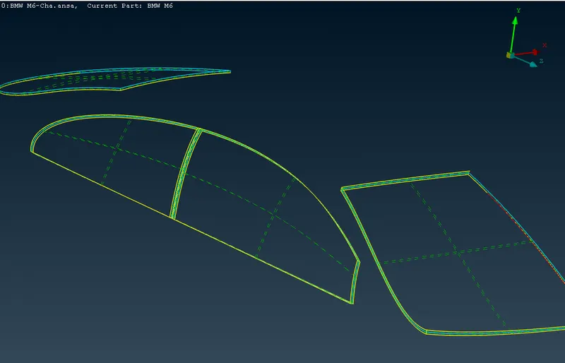
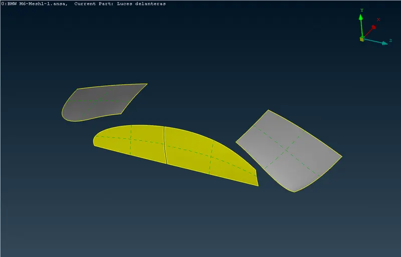
v) The isolated internal view of the windows after the geometric clean up. v) The wireframe view of the windows confirming the removal extra surfaces and resolution of the corresponding triple cons. 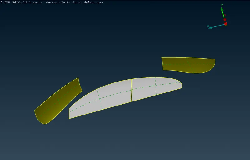
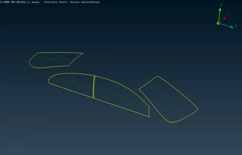
- Geometric clean up of the silencer.
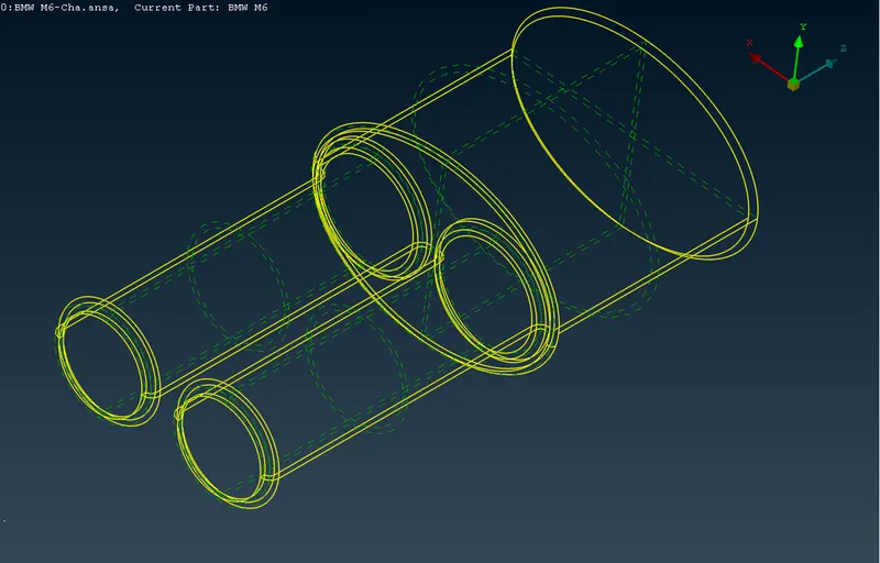
i) The isolated external view of the silencer. ii) The wireframe view of the silencer showing the thickness of the body and open volume of the body. 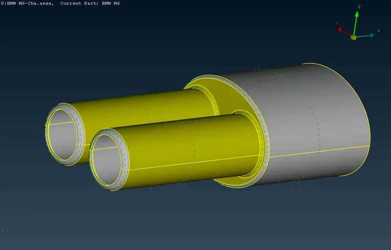
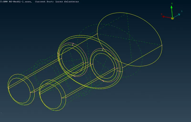
iii) After removing the extra surfaces reposible for thickness, the volume of the silencer has been closed by creating the surfaces into the both of exhaust pipes as shown below and deleteing the surface to creat single internal volume. iv) The wireframe view of the silencer after geometric clean up and confirmaing the single internal volume. 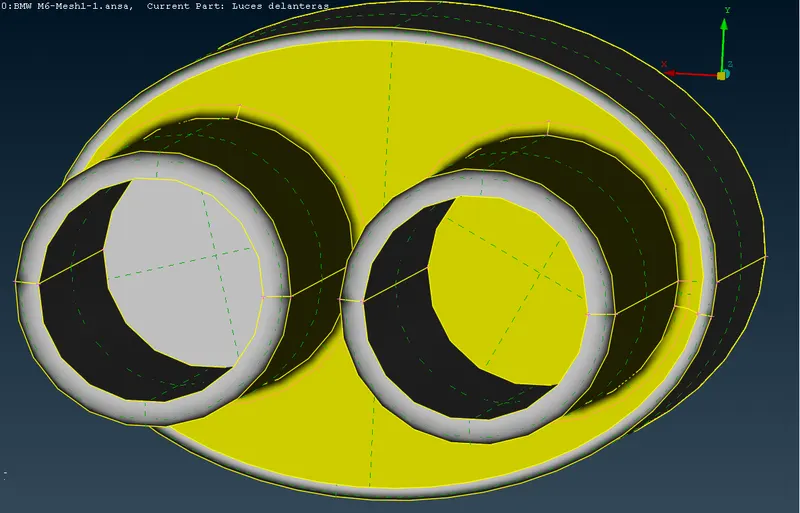
- Geometric clean up of the rims and tyres.
i) The external isolated view of the rims and tyres showing multiple triple cons. ii) The wireframe view of the rims and tyres showing the multiple internal surfaces. 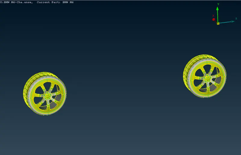
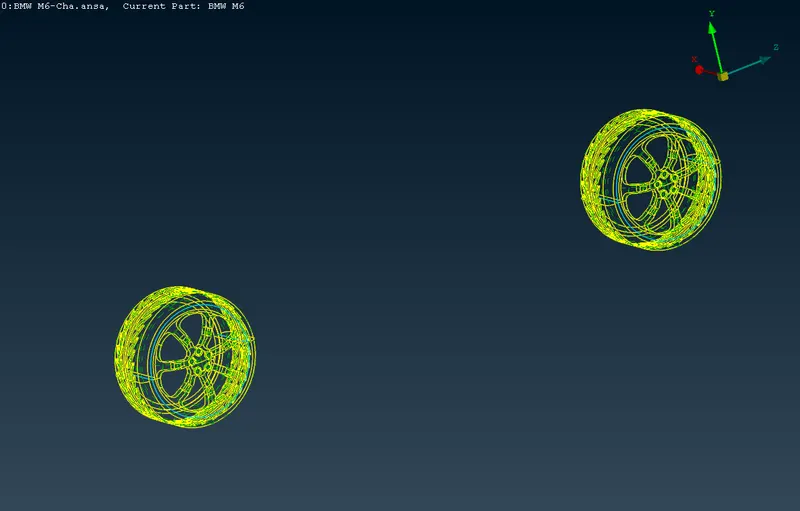
iii) The close wireframe view of the single tyre and rim showing multiple internal surfaces and corresponding triple cons. iv) The isolated external view of the rims and tyres after geometric clean up. 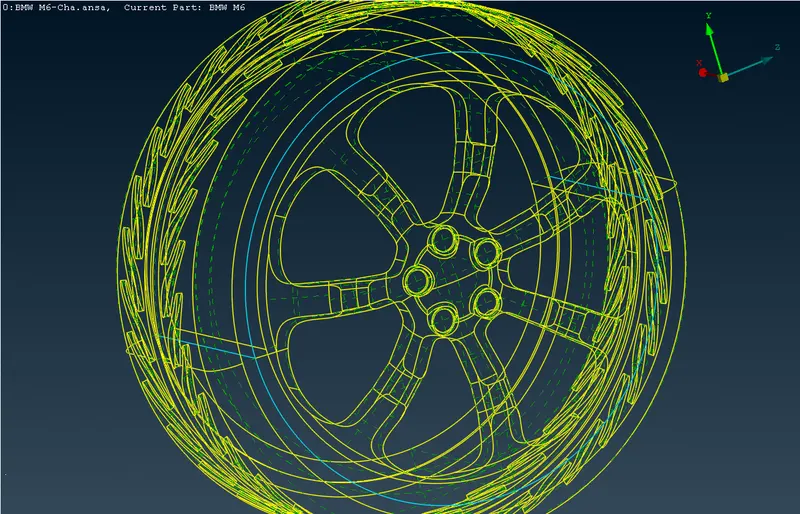
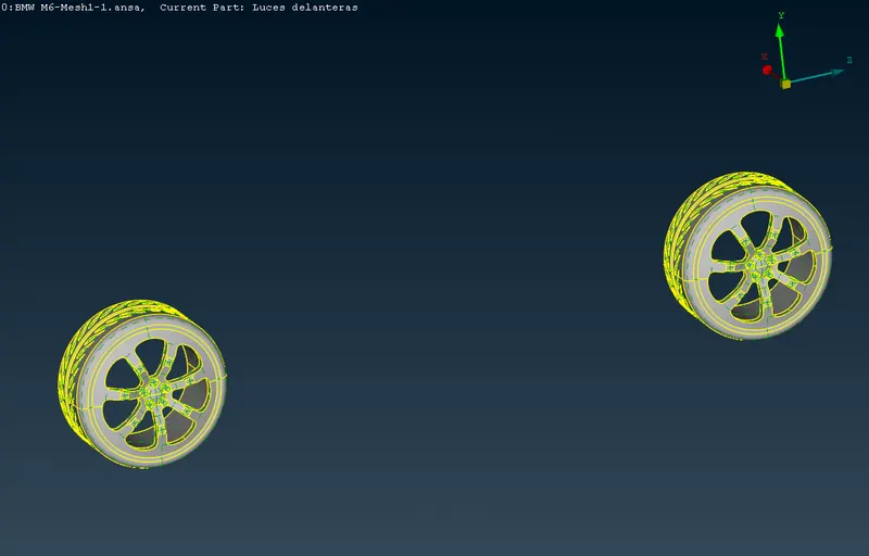
v) The wireframe view of the rim and tyres confirming no internal surface and single ingle internal volume. v) The some of the surface cuts are removed and some new are created to avoid the failure due to minimu length quality criteia. Following wireframe view shows the same. 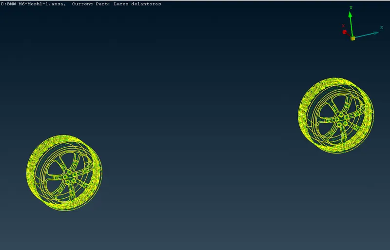
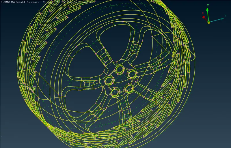
vi) The magnified view of the rim and tyre showing deleted cons and other geometric clean up. 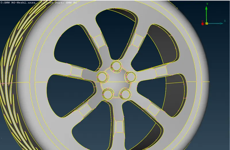
- Geometric clean up of the car body.
i) The isolated external front view of the car body showing the multiple single cons and triple cons at the conjuction of grills,lights,logo and windows. ii) The isolated external side view of the car body showing the multiple single cons and triple cons at the conjuction of grills,lights,logo and windows. Also the intersecting surfaces can be observed into the wheel space. 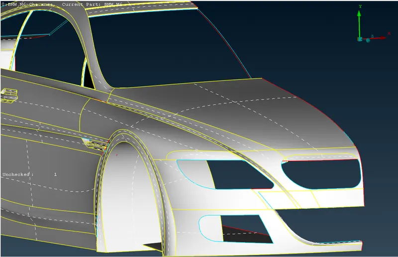
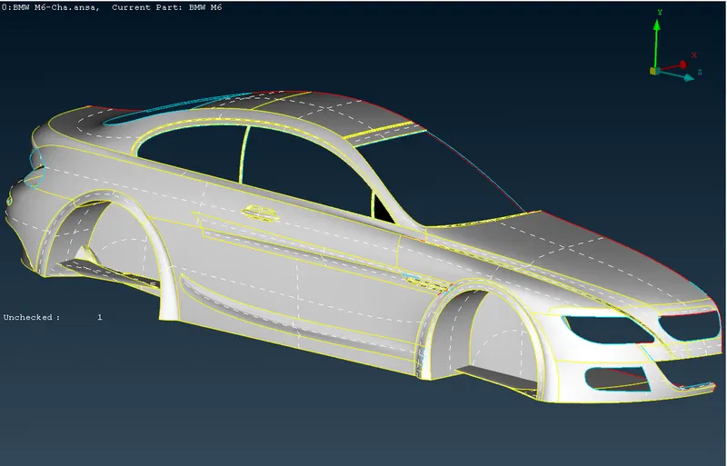
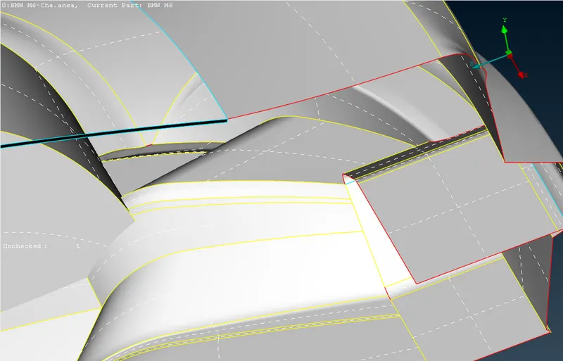
iii) The isolated external side view of the car body from rear angle showing the multiple single cons and triple cons at the conjuction of grills,lights,logo and windows. Also the intersecting surfaces can be observed into the wheel space. iv) The internal view of the car body showing single cons and triple cons along with extra surfaces. 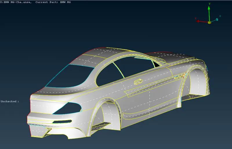
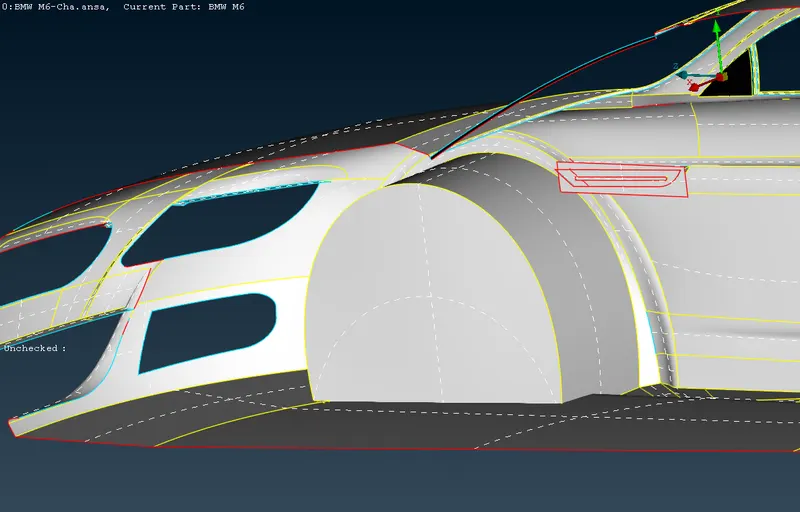
v) The internal view of the car body showing single cons and triple cons along with extra surfaces. vi) The internal view of the car body showing single cons and triple cons along with extra surfaces. 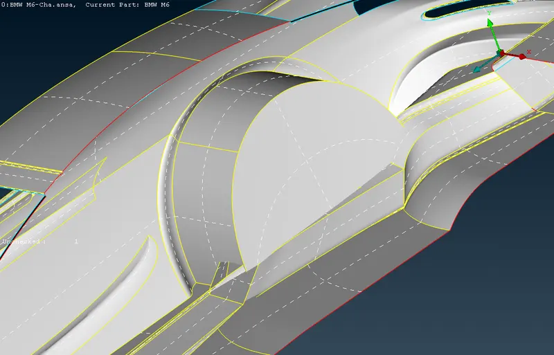
vii) The external front view of the car body after geometric clean up showing the removed unnecessary cons to avoid failure due to qualty criteria. viii) The external side view of the car body showing removal of the extra surfaces frrom the wheel spaces anf resolving multiple triple and single cons. 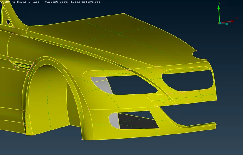
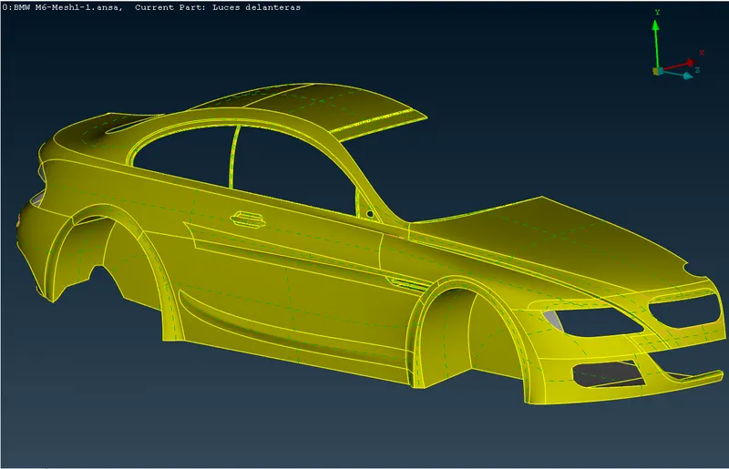
ix) The external side view from the rear angle showing geometric clean up of the car body. x) The internal view of the car body showing resolution of the multiple triple cons and removal of extra surfaces from the internal of the car body. 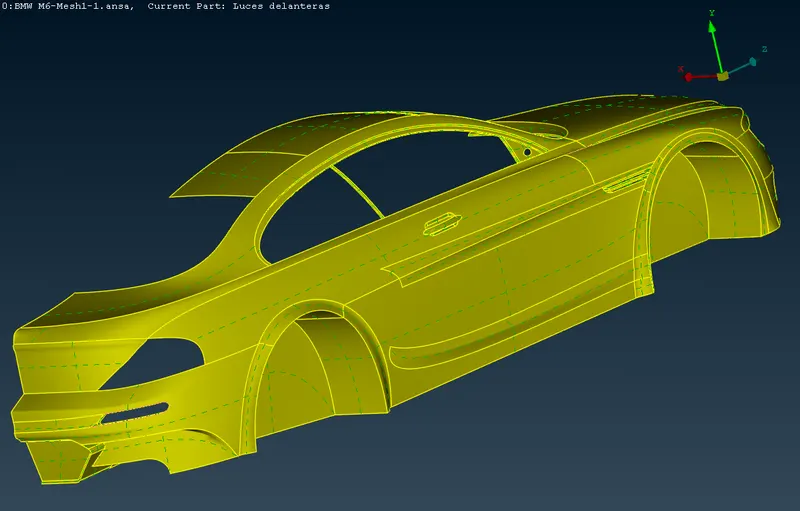
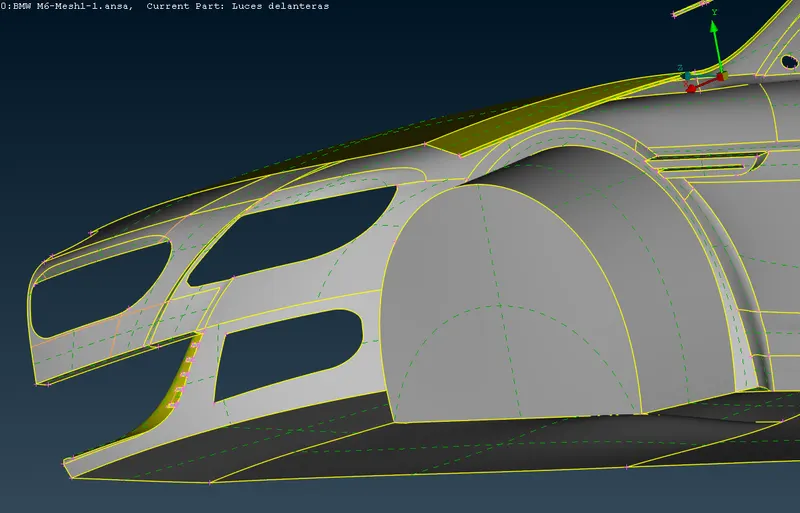
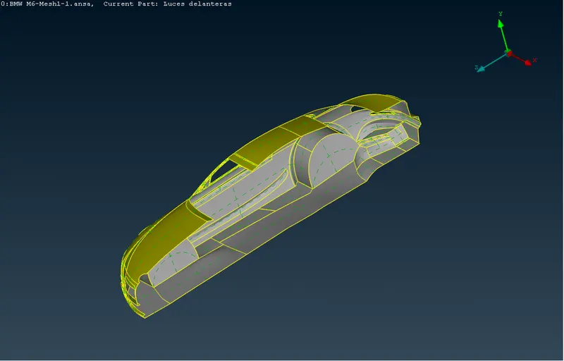
xi) The recreation of the bottom surfaces of the car body can seen in the following image. Extra surfaces have been removed. xii) The whole internal view of the car body showing recreated bottom surfaces and internal geometric clean up. 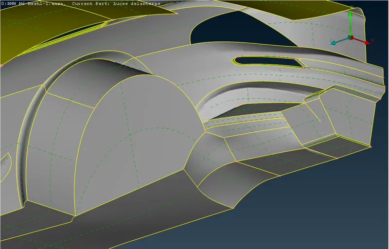
xiii) The front view showing grills, lights and logo along with car body. xiv) The rear view of the car bosy showing geometric clean up to avoid quality criteria failure due to the minimum length. 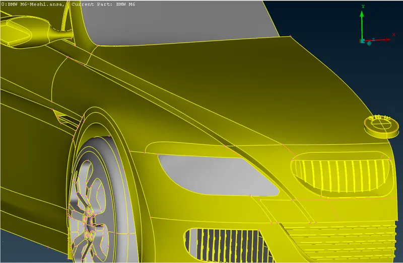
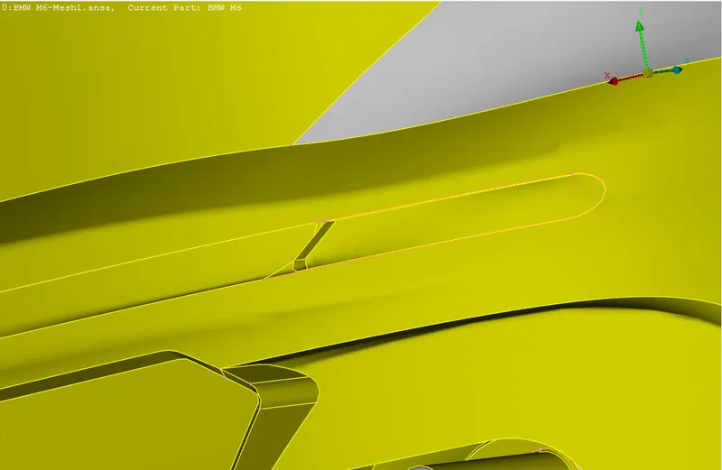
- PID assignment
i) Assigning the PID for logo. ii) Assigning the PID for grills. 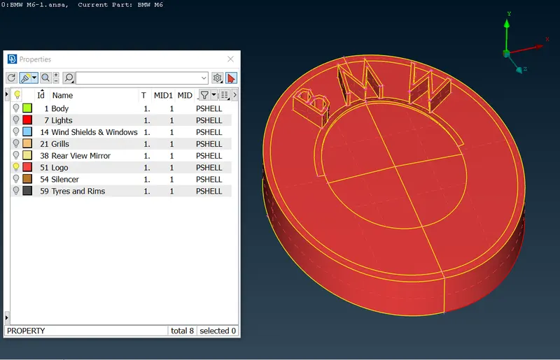
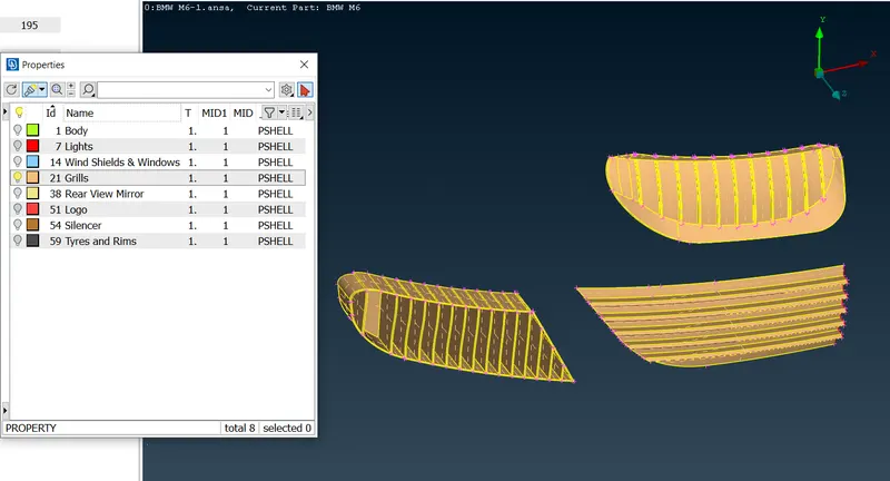
iii) Assigning the PID for lights. iv) Assigning the PID for windows. 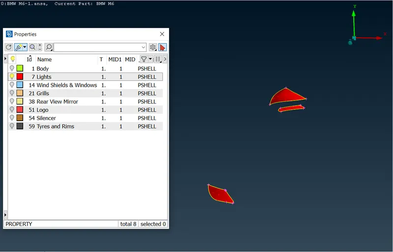
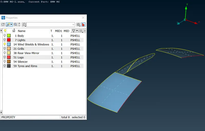
v) Assigning the PID for rear view mirror. vi) Assigning the PID for silencer. 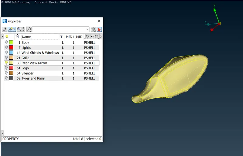
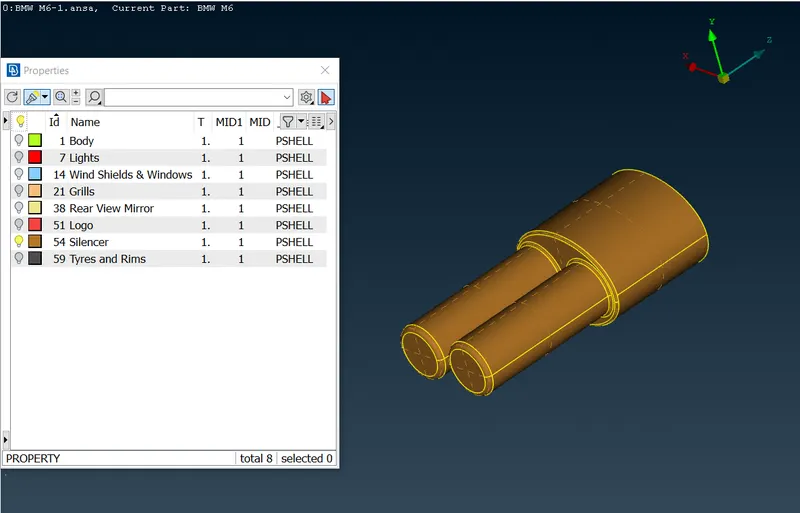
vii) Assigning the PID for rims and wheels. viii) Assigning the PID for car body. 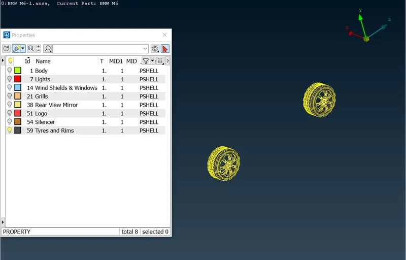
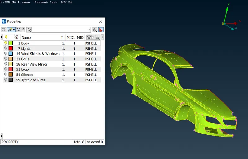
- Surface meshing of the grills with desired target lengths and quality.
a) All of the surface meshes are generated by isolating the respective PID then assigning the desired quality criteria along with mesh parameters. b) Into the mesh deck mesh perimeters and macros are assigned and mesh is generated with spotmesh-visible. Mesh is reconstructed whenever needed to minimize the numeber of off elements. i) The quality criteria for surface meshing of the grills. ii) The mesh parameters for surface meshing of hte grills. 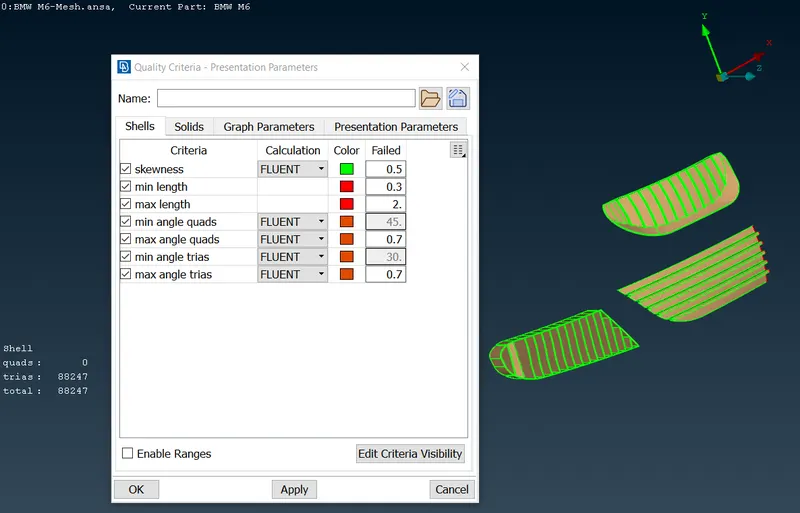
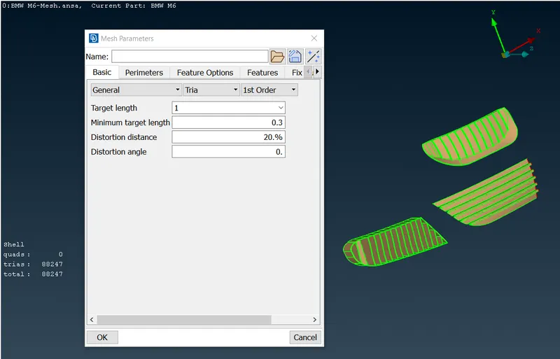
iii) The external view of the surface mesh of lower left grill. iv) The internal view of the surface mesh of lower left grill. 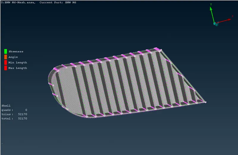
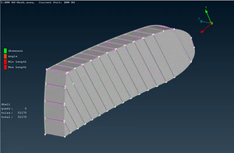
v) The external view of the surface mesh of lower right grill. vi) The internal view of the surface mesh of lower right grill. 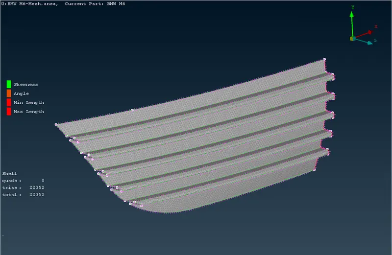
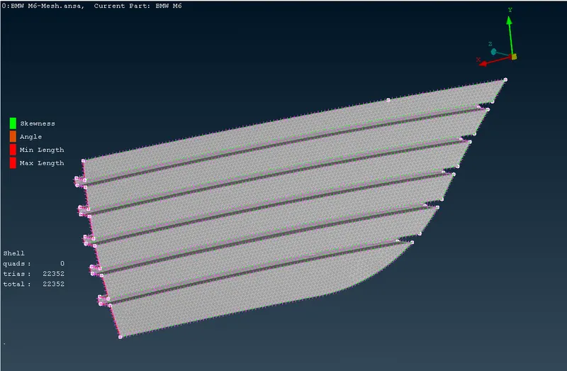
vii) The external view of the surface mesh of upper right grill. viii) The internal view of the surface mesh of upper right grill. 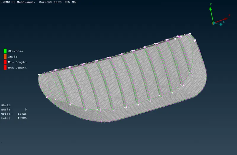
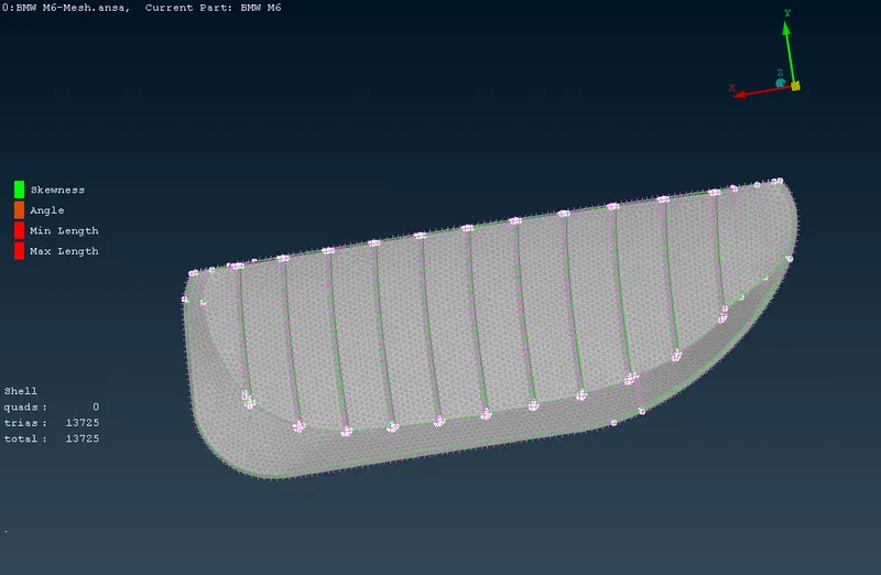
ix) The external view of the surface mesh of grills satisfying the desired mesh quality criteria. x) The internal view of the surface mesh of grills satisfying the desired mesh quality criteria. 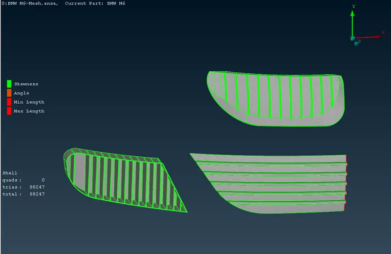
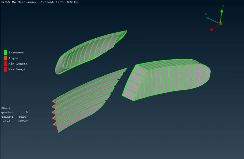
- Surface meshing of the lights with desired target lengths and quality.
i) The quality criteria for the surface meshing of the lights. ii) The mesh parameters for the surface meshing of the lights. 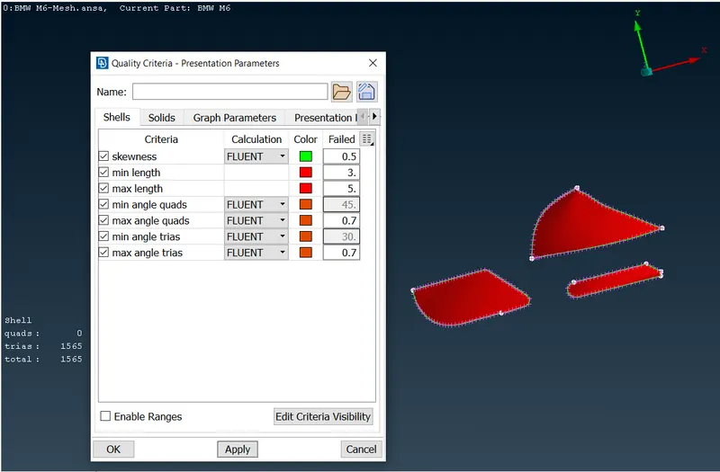
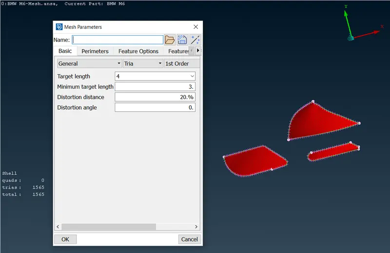
iii) The external view of the surface mesh of the front light. iv) The internal view of the surface mesh of the front light. 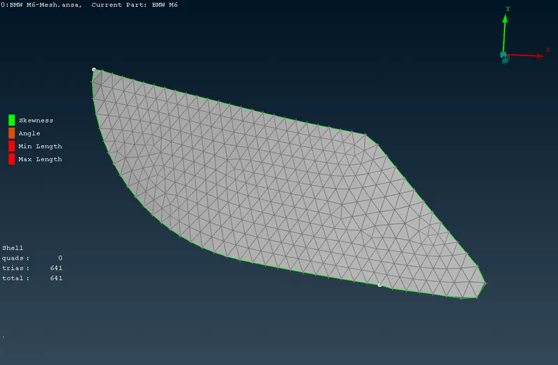
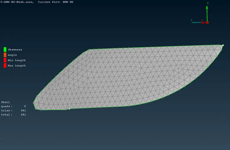
v) The external view of the surface mesh of the rear lights. vi) The internal view of the surface mesh of the rear lights. 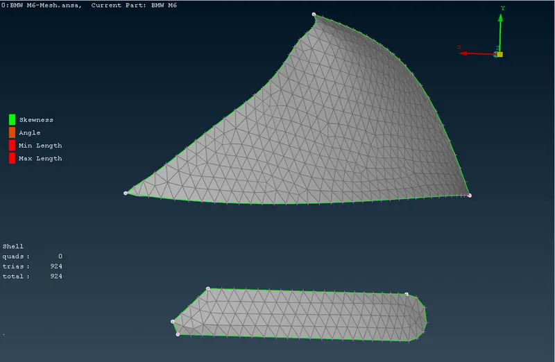
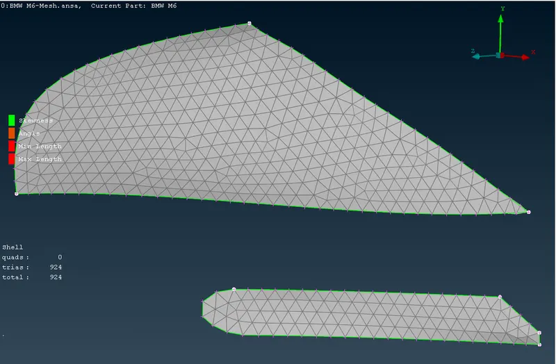
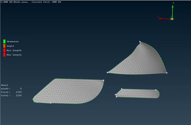
vii) The isolated front view of the surface mesh of the lights satisfying the desired mesh quality criteria. viii) The isolated rear view of the surface mesh of the lights satisfying the desired mesh quality criteria. 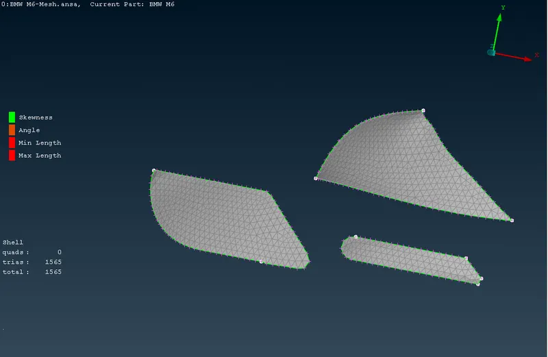
- Surface meshing of the logo with desired target lengths and quality.
i) The quality criteria for the surface mesh of the logo. ii) The mesh parmeters for the surface mesh of the logo. 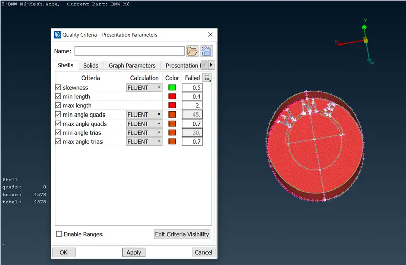
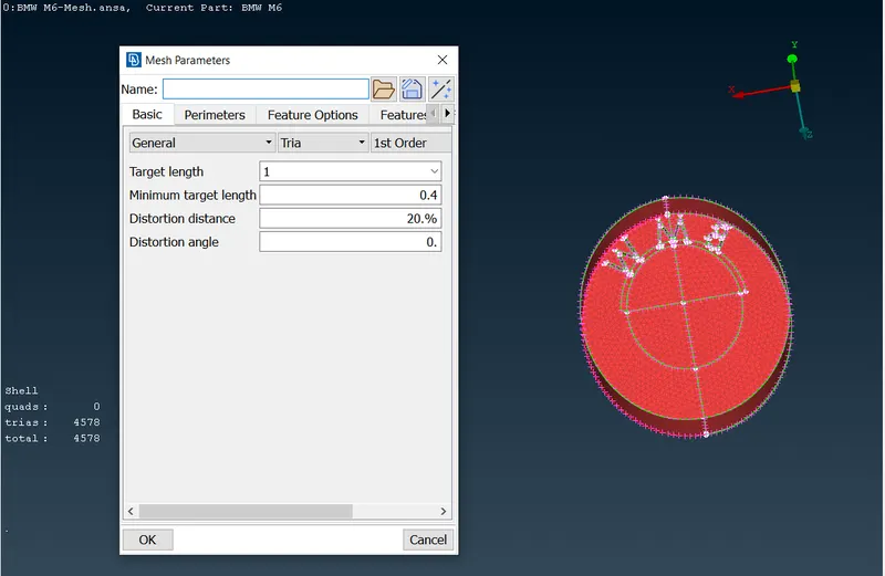
iii) The front view of the surface mesh of the logo satisfying the desired quality criteria. iv) The rear view of the surface mesh of the logo satisfying the desired quality criteria. 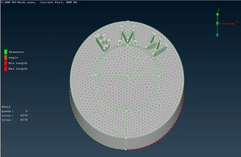
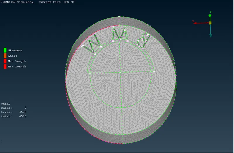
- Surface meshing of the rear view mirror with desired target lengths and quality.
i) The quality criteria for the surface mesh of the rear view mirror. ii) The mesh parameters for the surface mesh of the rear view mirror. 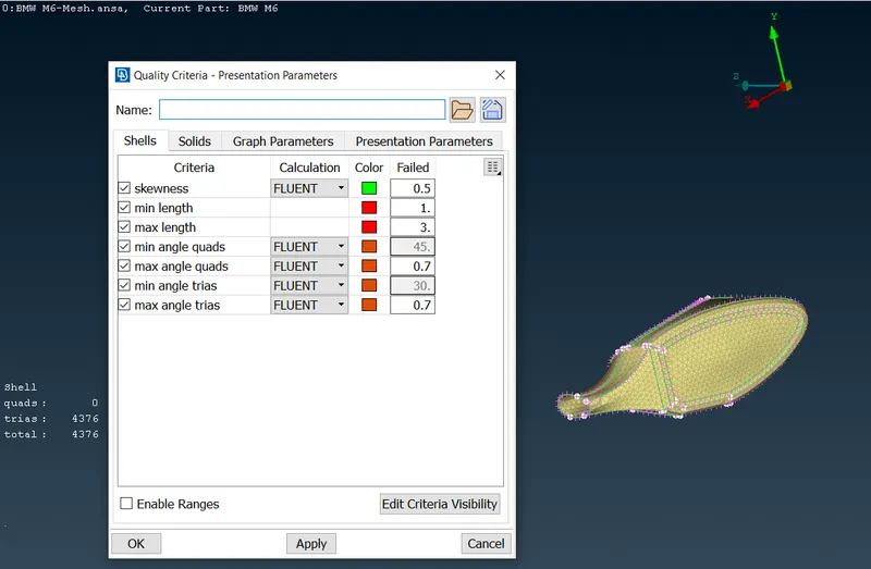
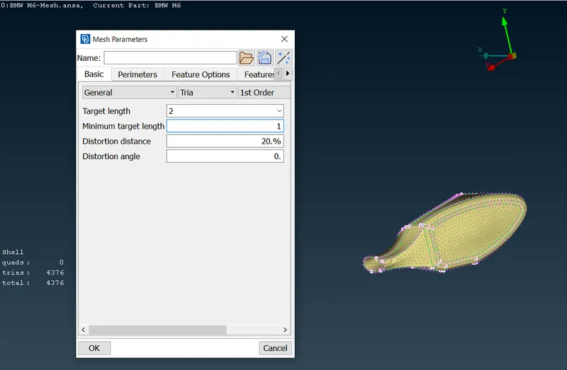
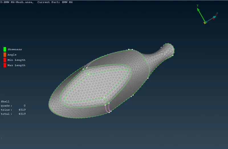
iii) The rear view of the surface mesh of the rear view mirror satisfying the desired quality criteria. iv) The front view of the surface mesh of the rear view mirror satisfying the desired quality criteria. 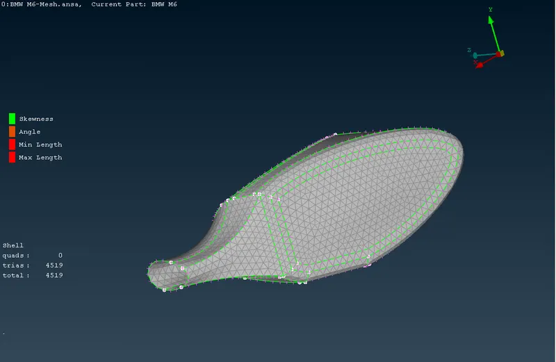
- Surface meshing of the windows with desired target lengths and quality.
i) The quality criteria for the surface mesh of the windows. ii) The mesh parameters for the surface mesh of the windows. 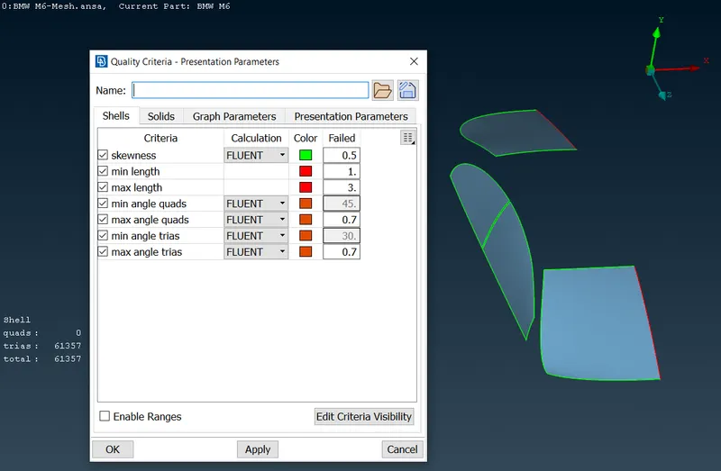
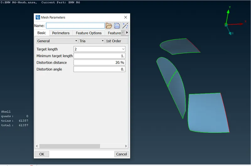
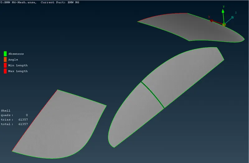
iii) The isolated external view of the windows surface mesh satisfying the desired quality criteria. iv) The isolated internal view of the windows surface mesh satisfying the desired quality criteria. 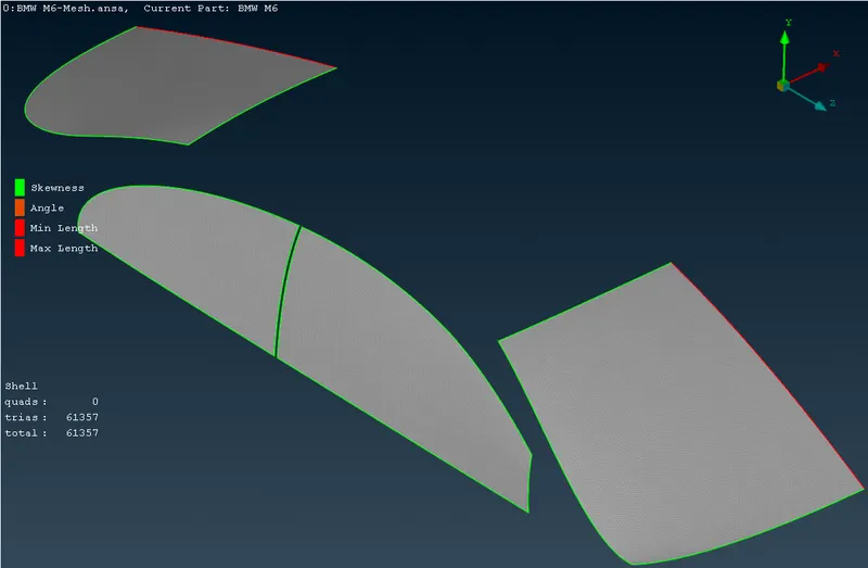
- Surface meshing of the silencer with desired target lengths and quality.
i) The quality criteria for the surface mesh of the silencer. ii) The mesh parameters for the surface mesh of the silencer. 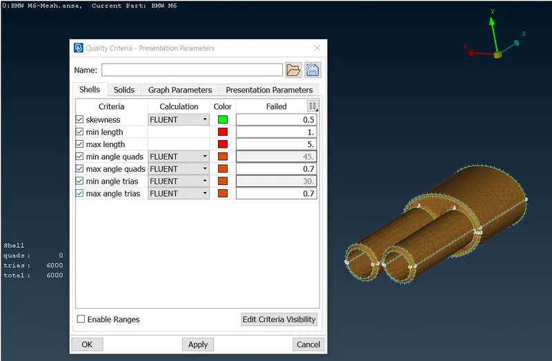
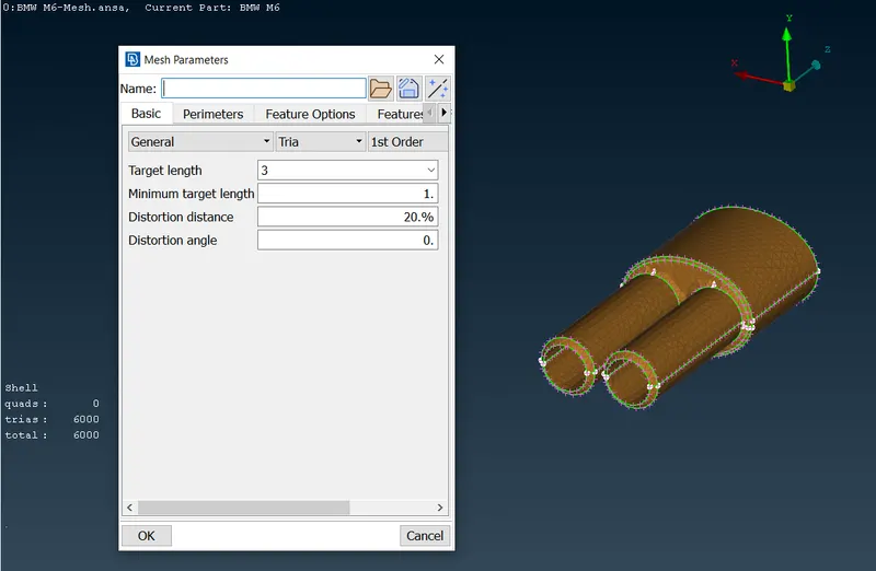
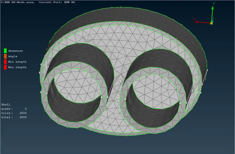
iii) The external view of the surface mesh of the silencer satisfying the desired qualtity criteria. iv) The another view of the surface mesh of the silencer satisfying the desired qualtity criteria 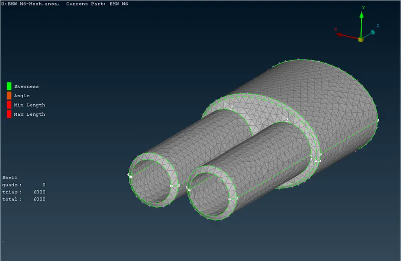
- Surface meshing of the rims and tyres with desired target lengths and quality.
i) The quality criteria for the surface mesh of the rims and tyres. ii) The mesh parameters for the surface mesh of the rims and tyres. 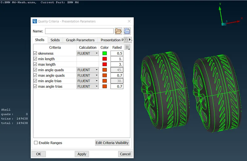
iii) The external side view of the rims and tyres showing surface mesh satisfying the desired quality criteria. iv) The external side view of the rims and tyres showing surface mesh satisfying the desired quality criteria. 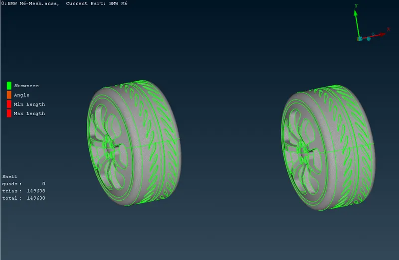
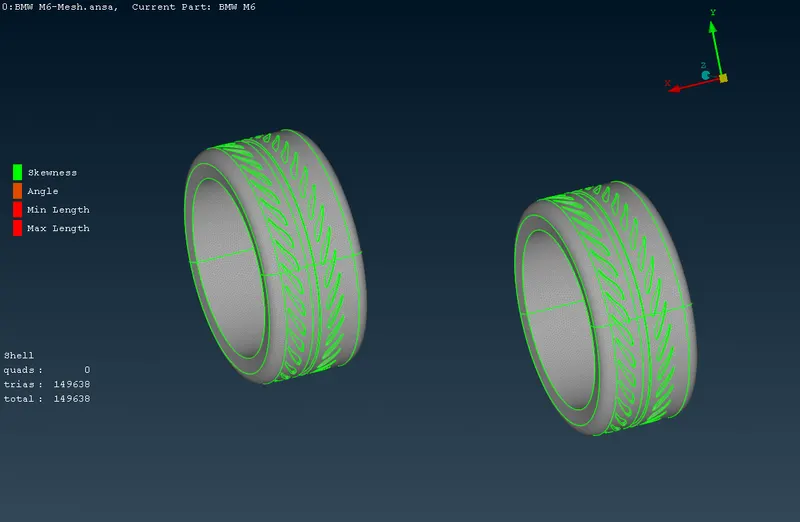
v) The close front view of the surface mesh of the rim and tyre. vi) The close front view of the surface mesh of the rim and tyre. 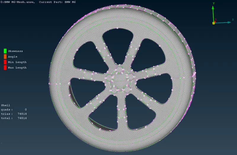
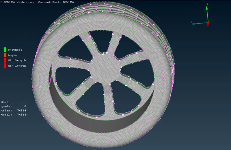
- Surface meshing of the the car body with desired target lengths and quality.
i) The quality criteria for the surface mesh of the car body. ii) The mesh parameters for the surface mesh of the car body. 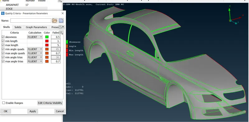
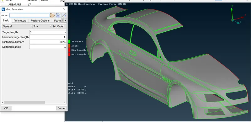
iii) The wireframe view of the selected necessary cons for assigning the mesh perimeters. Macros are not assigned for this PID as it has been connected with multiple PIDs with different macros. iv) The mesh is generated with the spotmesh visible anf see the number of off elements is arount 1227. To minimize the same the mesh has been reconstructed. 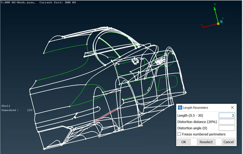
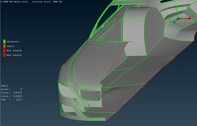
v) Reconstructing the whole mesh of the PID-car body. vi) After reconstructing the mesh the count of off elements has been reduced to 520. 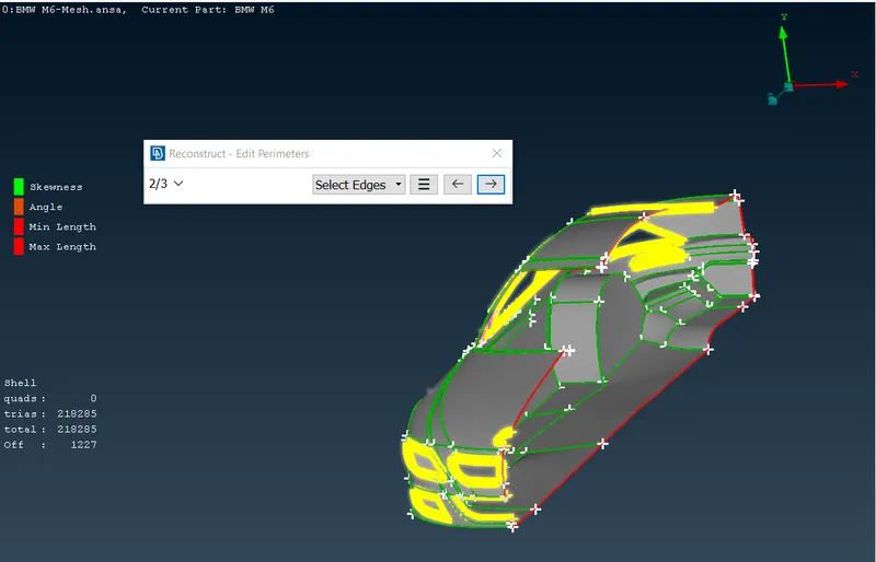
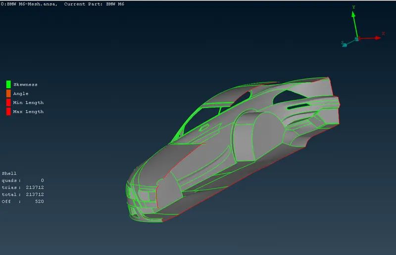
vii) Most of the off elemetns are present at the conjection of car body with the grills, logo and lights. This is shown in the following figure. viii) The off elements are eliminated by move and paste node command along with split elements command, by this way the off elements are eliminated. 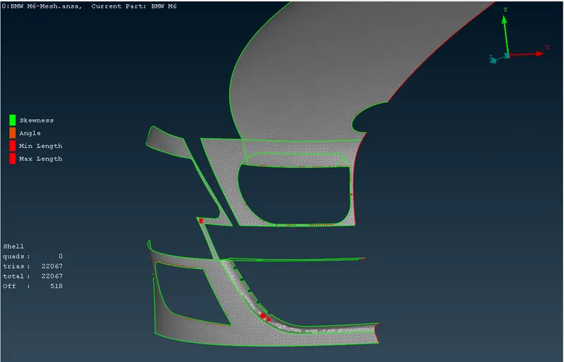
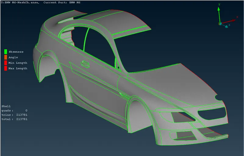
- To copy the model on the other side with the symmetry option and its geometric clean up
i) The half car model with full surface mesh, without any off element. The off elements are shown in the following figure due to different quality criteia and mesh parameters assigned for different PIDs. ii) The half car model has now been replicated on other side with transform>copy>Entities>Symmetry command. As logo is not symmetric, it has been deselected from the group of symmetric entities. 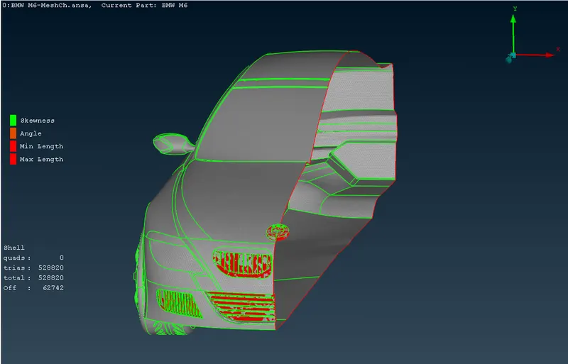
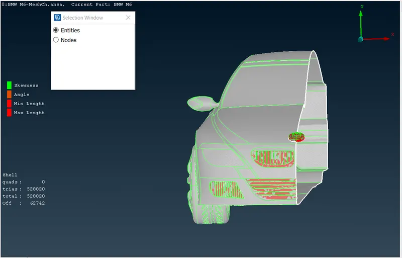
iii) For the symmetry transformation 3 points from the plane of symmetry has been selected. iv) After finishing the symmetry transformation commmand. The full car model is as shown below showing some single cons not connected properly to make double con. Same has been resolved using cons>paste command. 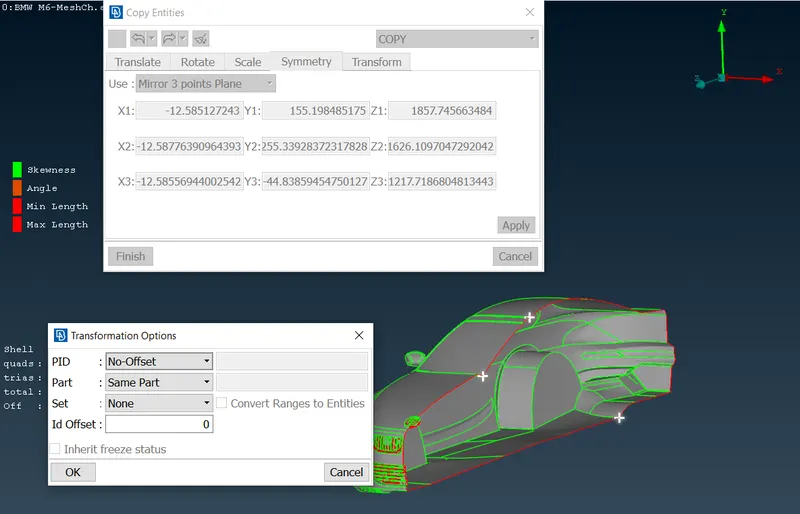
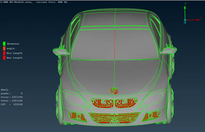
v) The finished full car model - Front view. vi) The finished full car model - Top view. 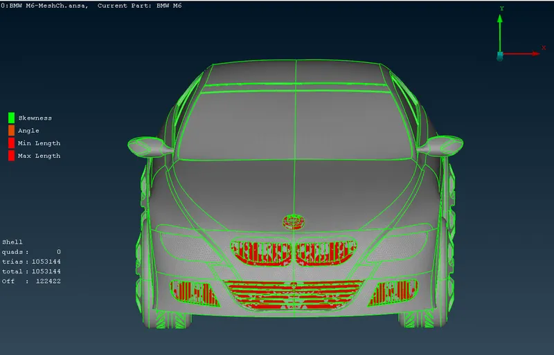
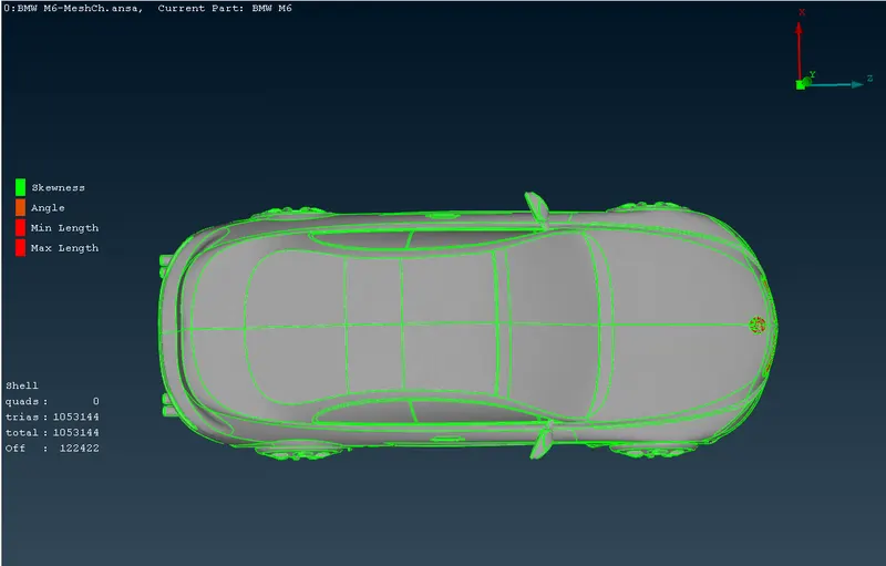
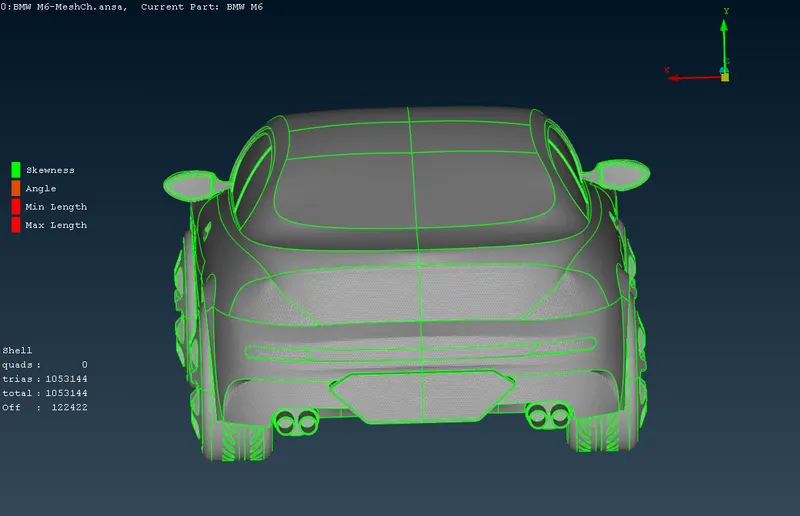
vii) The finished full car model - Bottom view. viii) The finished full car model - Rear view. 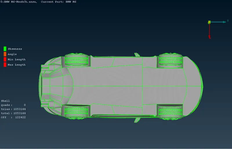
ix) The finished full car model - Front view with PIDs. x) The finished full car model - Rear view with PIDs. 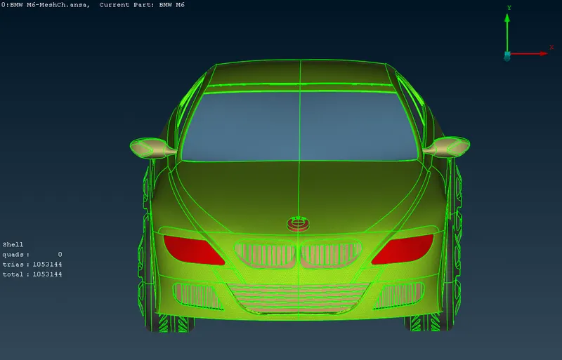
By this way the fully surface meshed car model has been created. The approximate centre of the bottom surface has been marked and point has been inserted at the same place.
- To creat wind tunnel.
i) The length=1300 mm, height=300 mm and width=500 mm of the car has been measured. Same has been depicted here. ii) The reference point for the bottom surface for wind tunnel has been inserted using Topo>Points>Relative method at the 75 mm below the bottom surface of the car. Same has been shown below. 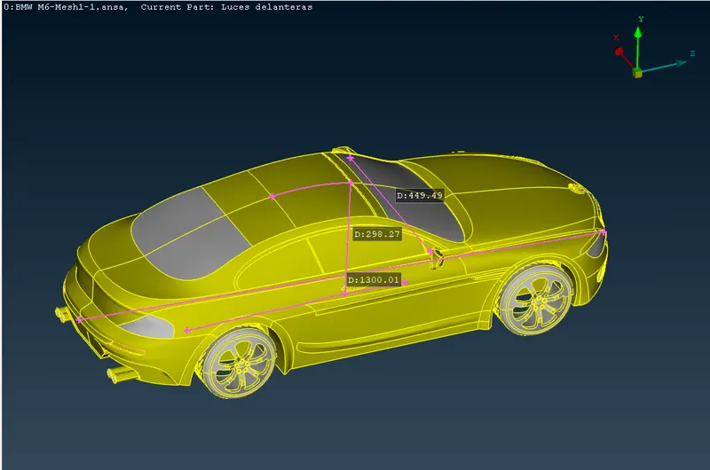
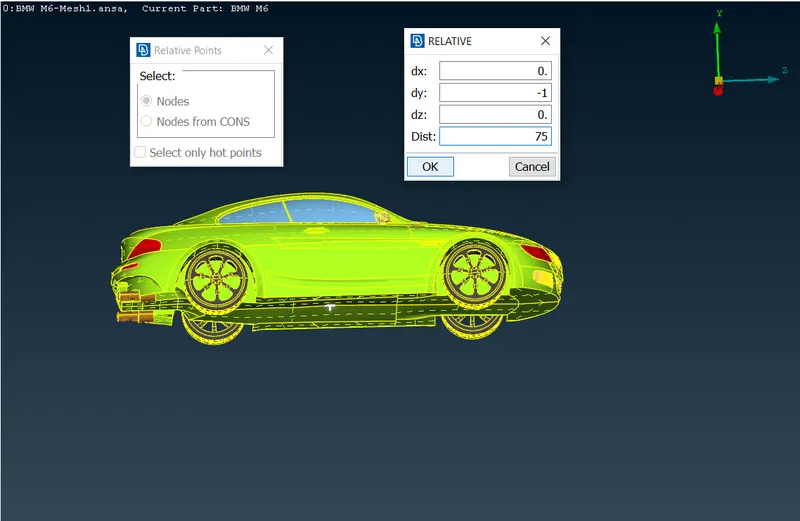
iii) Similarly the reference point for front surface of wind tunnel has been inserted using Topo>points>relative method at the distance of 4 times of length of car from leading edge of the car. i.e. at the distance of 5850 mm in the +'ve Z direction. iv) Similarly the reference point for rear surface of wind tunnel has been inserted using Topo>points>relative method at the distance of 6 times of length of car from trailing edge of the car. i.e. at the distance of 8450 mm in the -'ve Z direction. 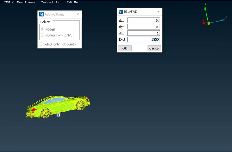
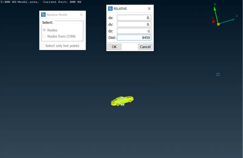
v) Similarly the reference points for side surface of wind tunnel has been inserted using Topo>points>relative method at the distance of 1 times of length of car from side edge of the car. i.e. at the distance of 1550 mm in the -'ve X direction. vi) Similarly the reference points for other side surface of wind tunnel has been inserted using Topo>points>relative method at the distance of 1 times of length of car from side edge of the car. i.e. at the distance of 1550 mm in the +'ve X direction. 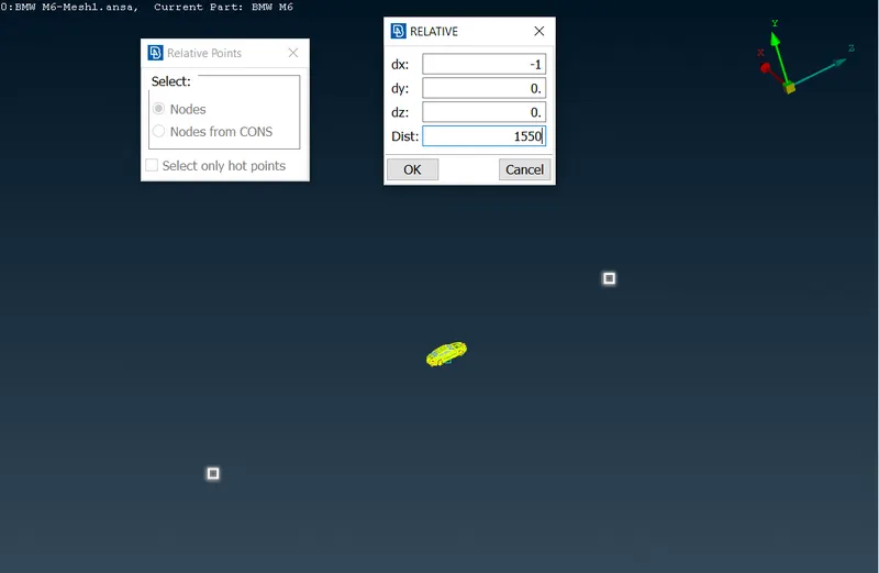
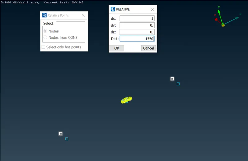
vii) The all reference points inserted are shown in the figure below. viii) The curves have been generated using inserted points to creat bottom surface, as shown below using curves>create command. 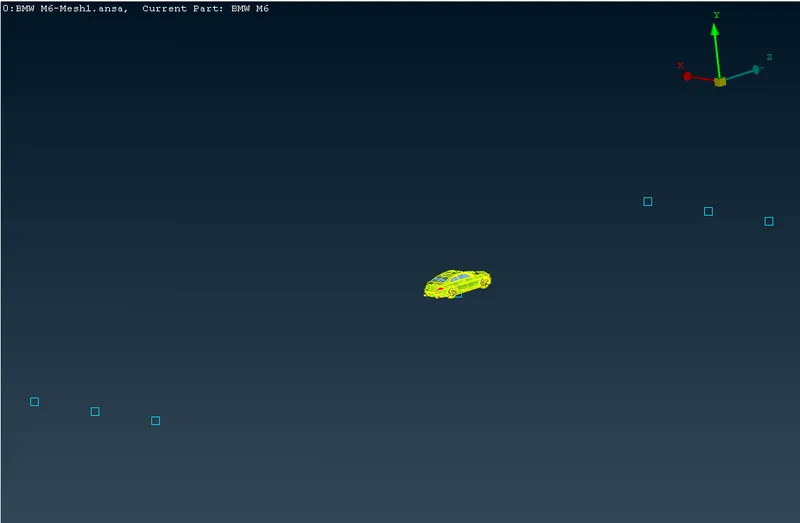
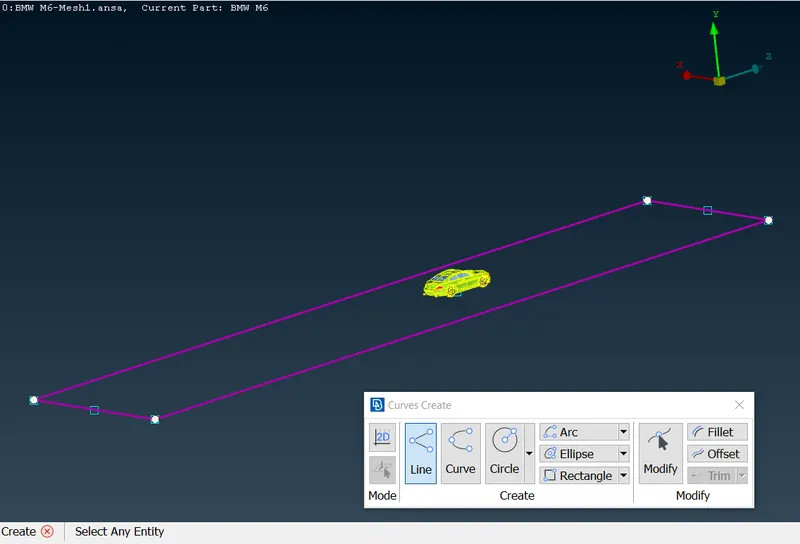
ix) The bottom surface has been generated using coons command. x) Respective PID has been created for bottom surface. 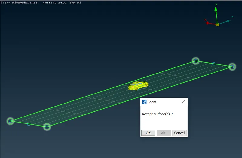
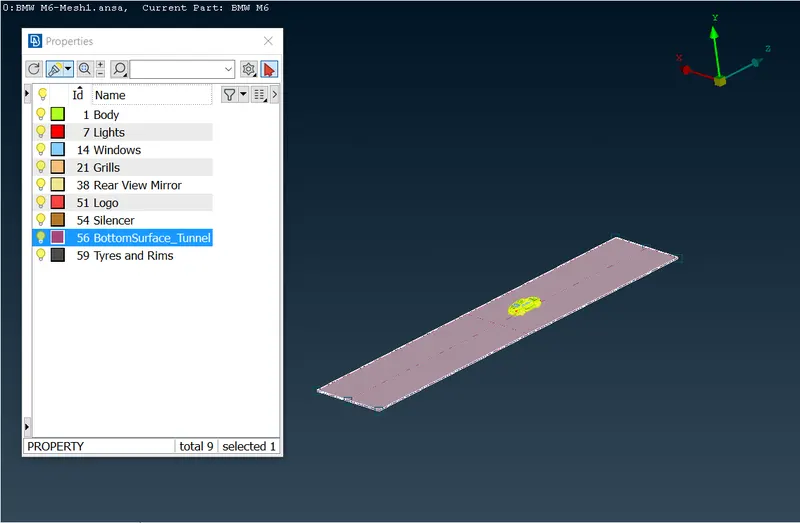
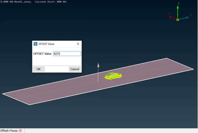
xi) The created points and curves have been deleted once the bottom surface has been created. xii) The top surface of the wind tunnel has been created using Topo>faces>offset command. By using offseting value as 4275 and retaining the original surface. 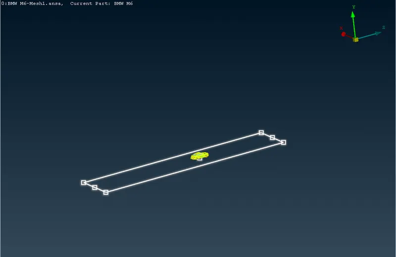
xiii) The wind tunnel rear surface has been created using coons command and selectecting the respective edges of the bottom ans top tunnel surfaces. xiv) The wind tunnel front surface has been created using coons command and selectecting the respective edges of the bottom ans top tunnel surfaces. 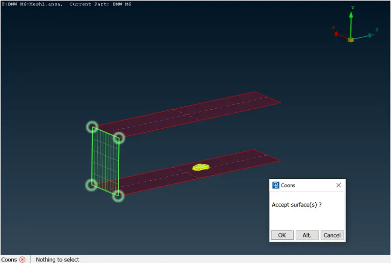
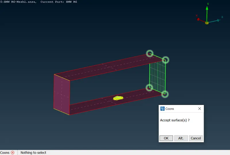
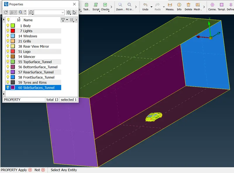
xv) The wind tunnel one of the side surface has been created using coons command and selectecting the respective edges of the already created tunnel surfaces. xvi) The wind tunnel other side surface has been created using coons command and selectecting the respective edges of the already created tunnel surfaces. 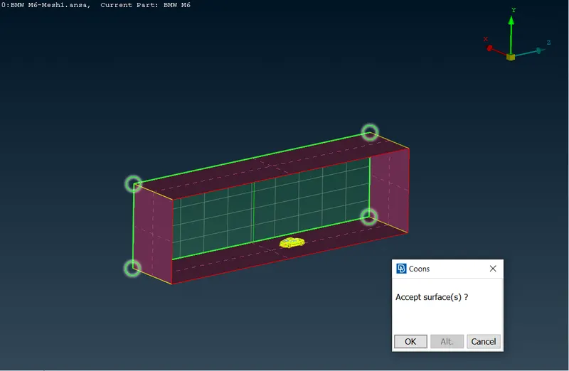
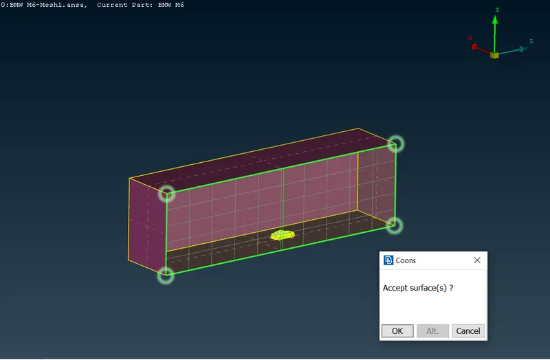
xvii) Assigning the PID for Top surface of tunnel. xviii) Assigning the PID for Rear surface of tunnel. 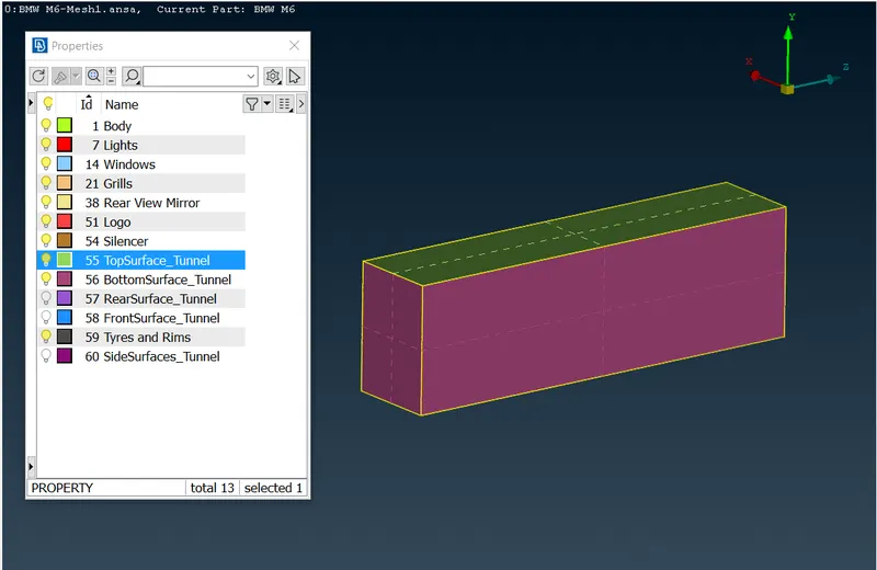
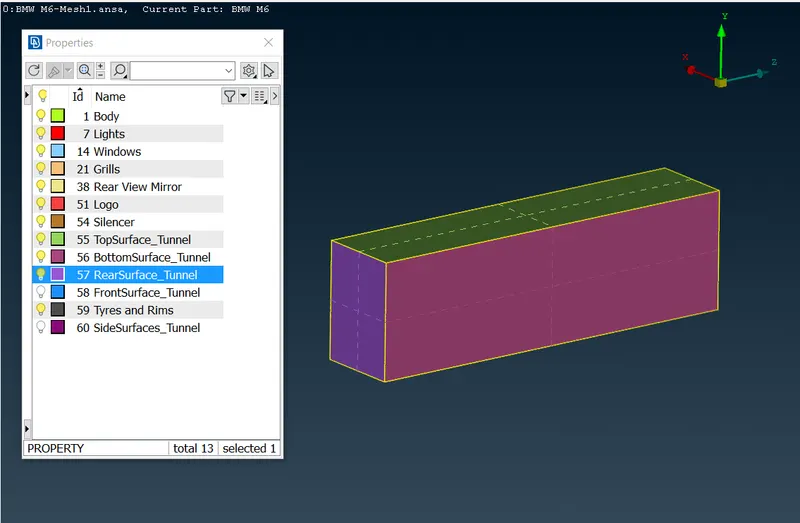
xix) Assigning the PID for front surface of tunnel. xx) Assigning the PID for both side surfaces of tunnel. 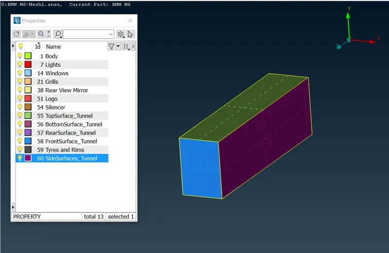
- Surface meshing of the wind tunnel surfaces with desired target lengths and quality.
i) The quality criteria for surface mesh of bottom tunnel surface. ii) Mesh parameters for bottom tunnel surface. 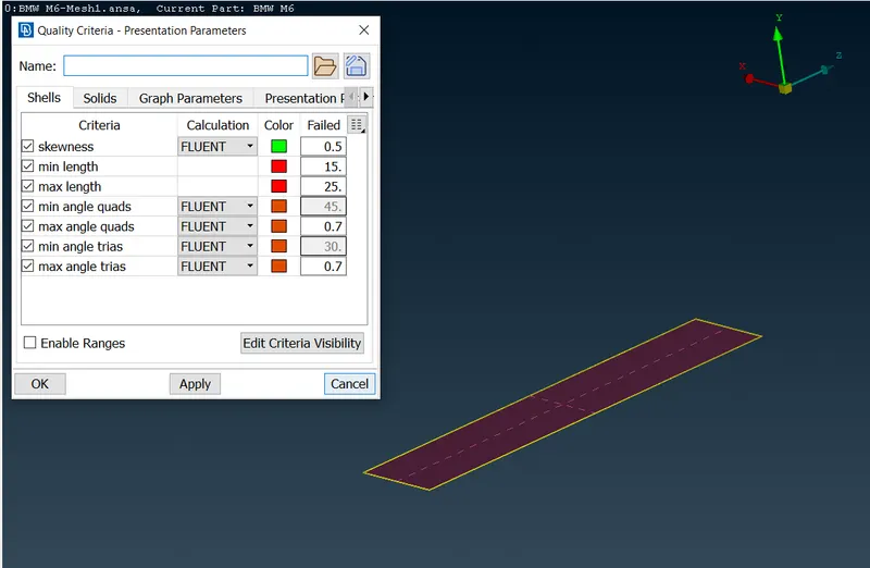
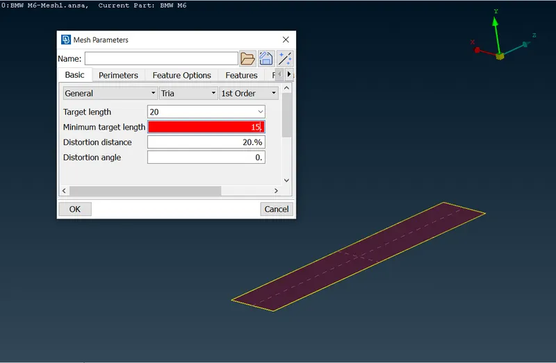
iii) The Mesh>Length>Perimeters for bottom tunnel surface. iv) The Mesh>Length>Macros for bottom tunnel surface. 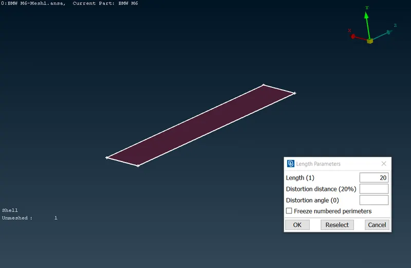
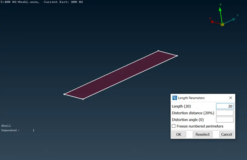
v) The surface mesh for bottom tunnel surface has been genertated using spotmesh visible. vi) The quality criteria for surface mesh of top tunnel surface. 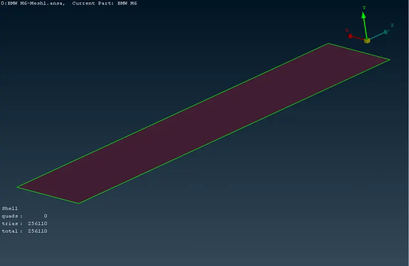
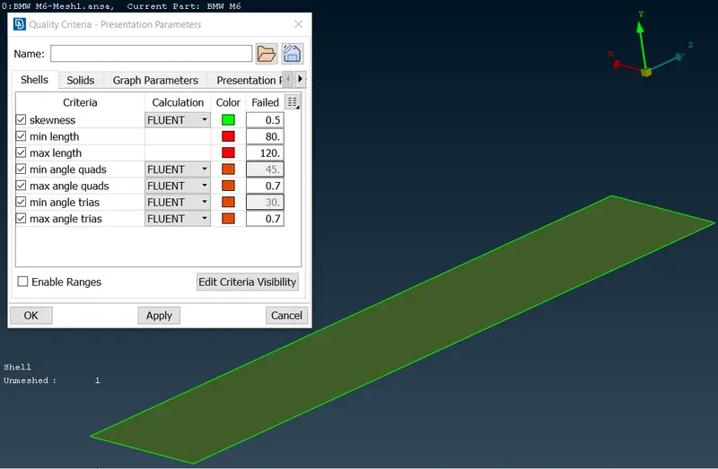
vii) Mesh parameters for top tunnel surface. viii) The Mesh>Length>Perimeters for top tunnel surface. 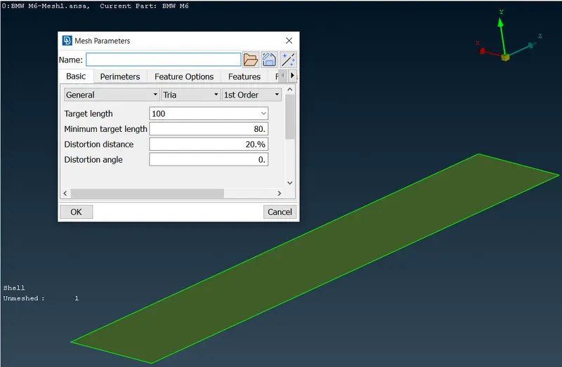
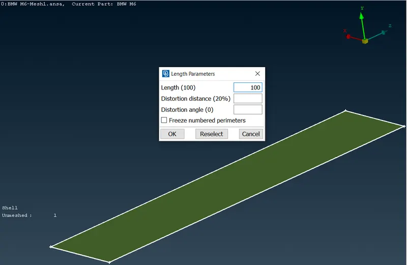
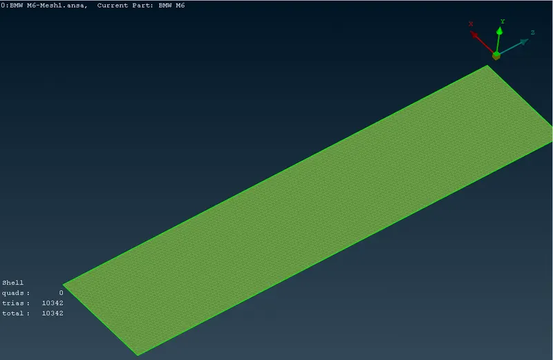
ix) The Mesh>Length>Macros for top tunnel surface. x) The surface mesh for top tunnel surface has been genertated using spotmesh visible. 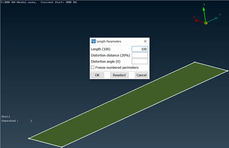
xi) Image showing the front, rear and two side surfaces remained unmeshed. xii) The shown settings for Mesh>Perimeters>Spacing>Geometric have been applied to the respective four edges. 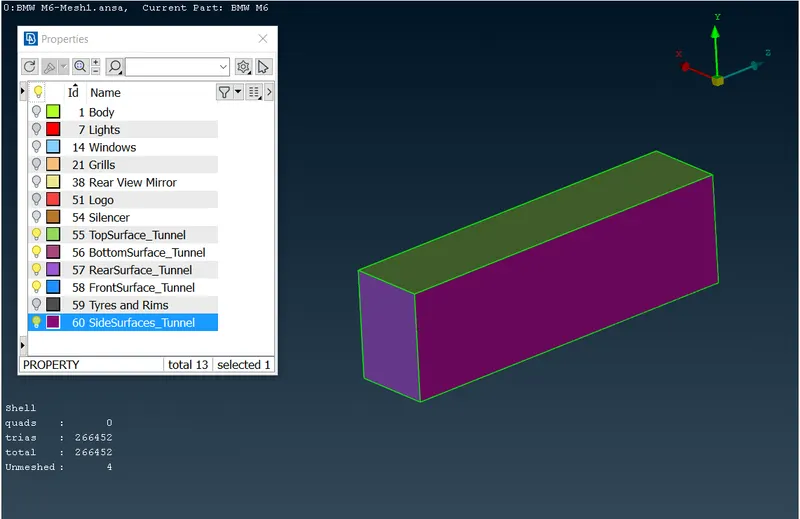
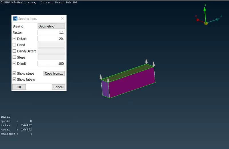
xiii) The rear tunnel surface has been surface meshed using spotmesh visible. xiv) The front tunnel surface has been surface meshed using spotmesh visible. 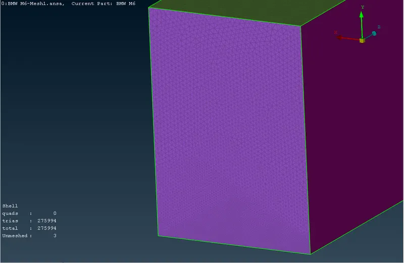
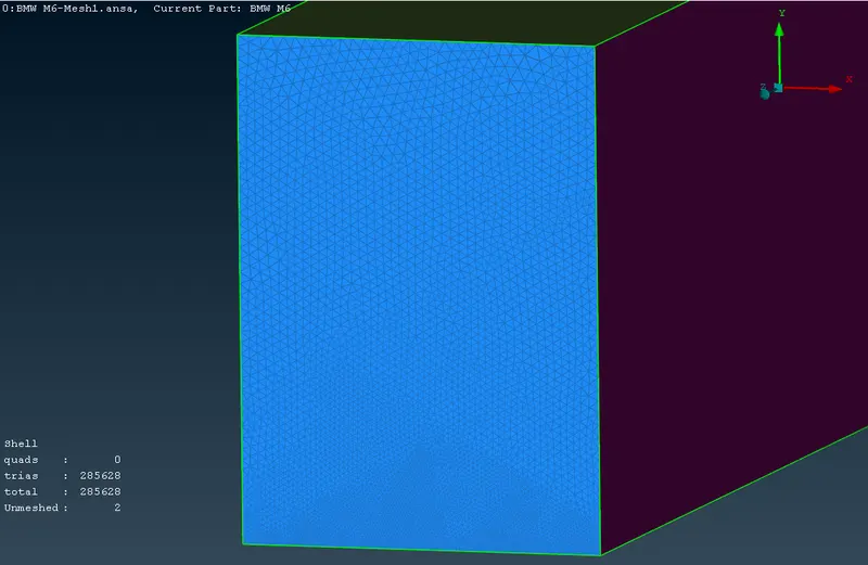
xv) The one of the side tunnel surface has been surface meshed using spotmesh visible. xvi) Similarly the other side tunnel surface has been surface meshed using spotmesh visible. 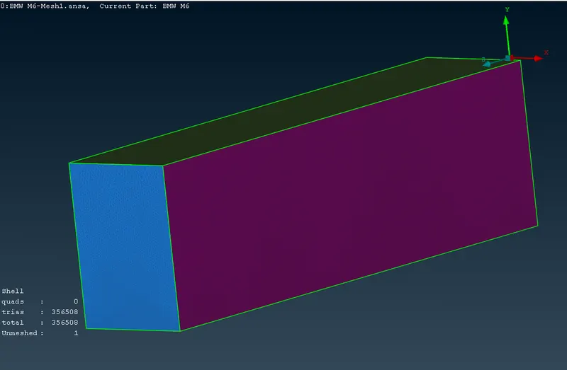
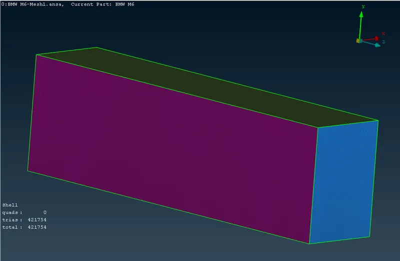
xvii) The all tunnel surfaces have been surface meshed. xviii) The wireframe view of the whole model. 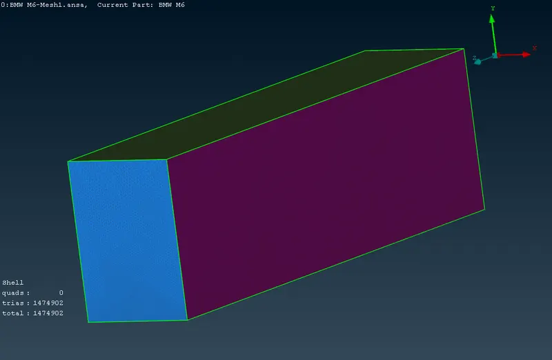
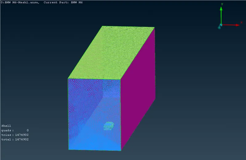
- Volume Meshing of the wind tunnel volume.
a) The model with all surfaces meshed with the desired quality criteria is taken for the volume meshing. b) To auto detect the various volumes from the model using Volume>Define command on whole database. i) The following error have been encounterd. ii) The errors are regarding penetration, duplicate and macro internal bounds. 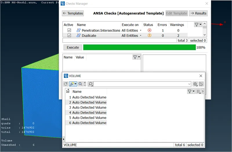
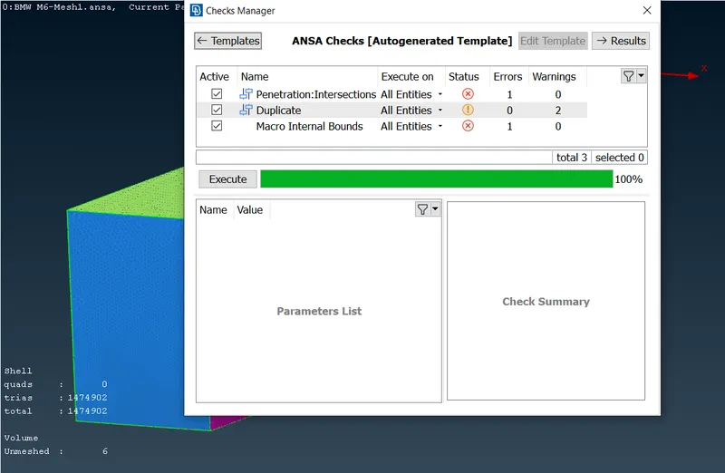
iii) By double clicking the penetration error and fixing it by right clicking on the error resolves the error, as shown below. iv) Duplicate error: The respective portion of the model have been isolated using show only command. 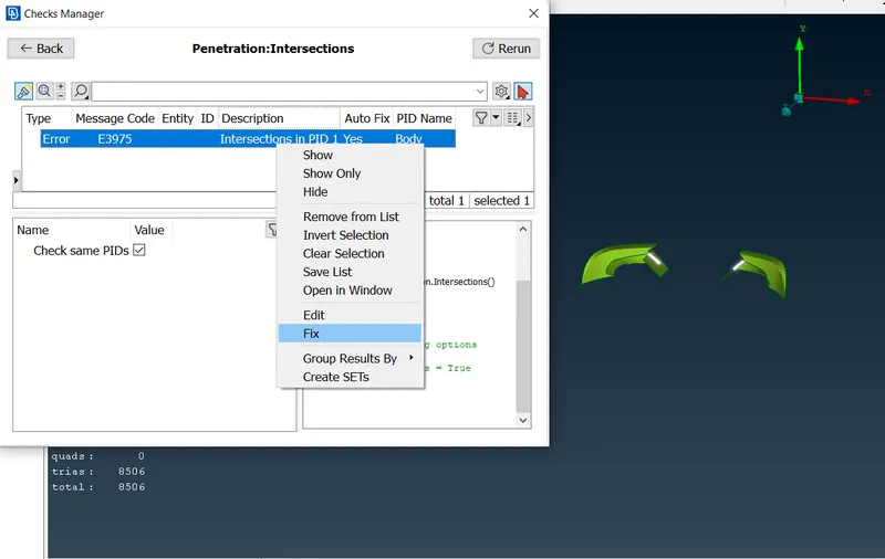
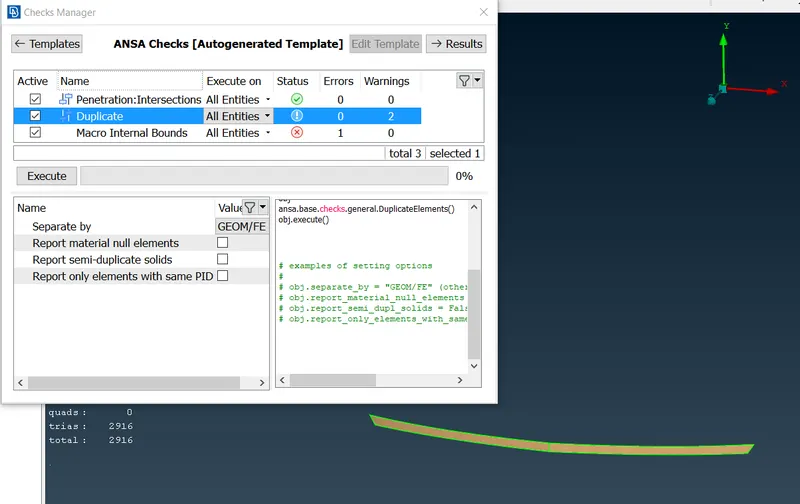
v) By double clicking the dupplicate error and fixing it by right clicking on the error resolves the error, as shown below. vi) By this time the macro internal bound error resolved automatically. It migh be related to the duplicate error. 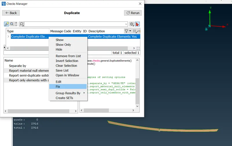
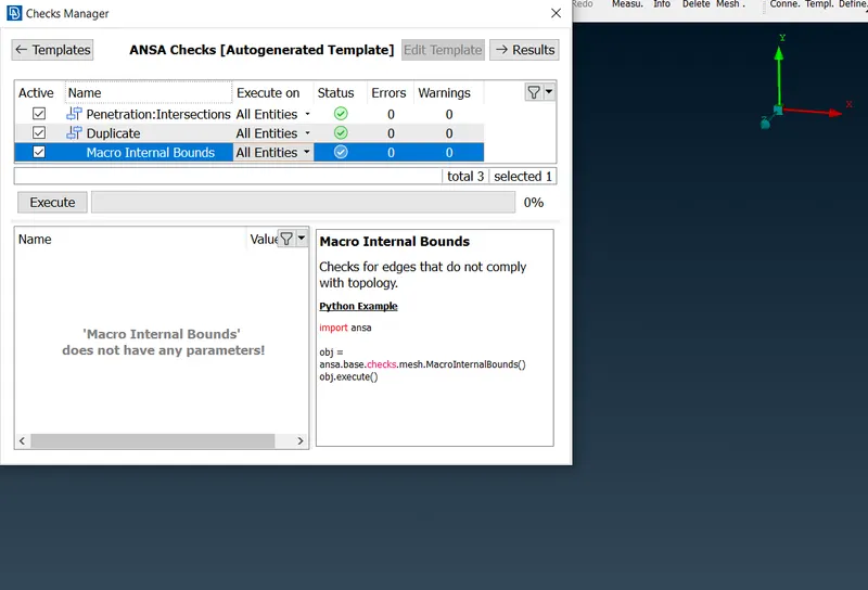
vii) Now again auto detecting the volumes, all possible volumes are detected and enlisted as shown below. viii) The volumes resposible for tyres and silencer are shown here. 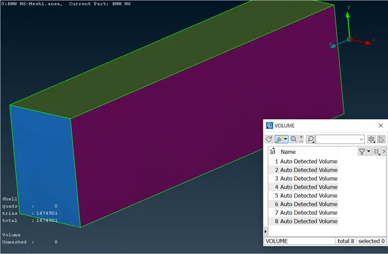
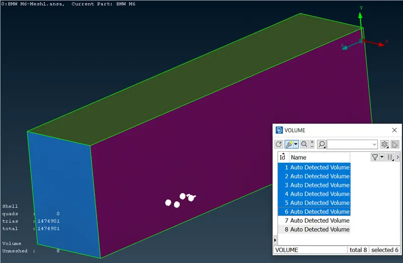
ix) The car body internal volume has been shown here. x) The volume of wind tunnel except car and other associated volumes is shown here. This is the required volume for volume meshing. 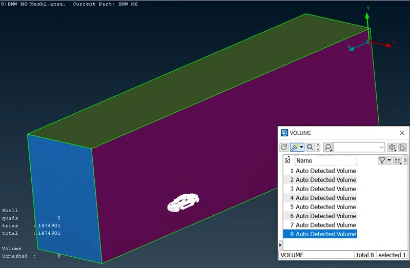
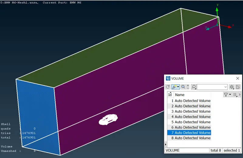
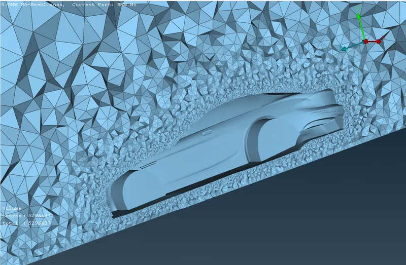
xi) Other volumes have been deleted using right click delete command. And the respective volume has been volume meshed using right click remesh command.The type has been selected as Tetra CFD. xii) Cross sectional view of the volumetric mesh around the car. 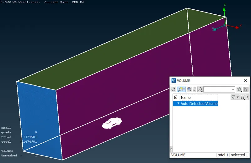
xiii) Full cross sectional view of the wind tunnel volume. xiv) transverse and longitudinal cross sectional view showing cross section front tyre and car body. 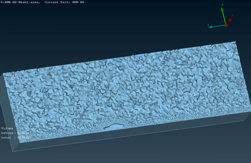
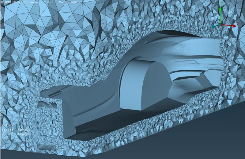
xv) The whole wind tunnel volume. xvi) The whole wind tunnel volume with geometry. 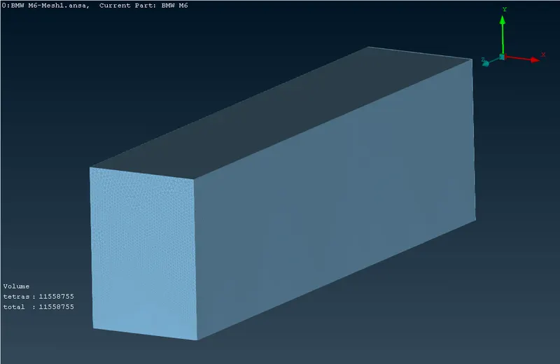
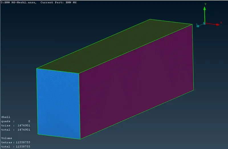
I) As Volumetric Mesh model compressed file is around 175 MB in size. It can't be uploaded here.So kindly consider the google drive link to download it. The link is as follows II) Please find the model compressed file till the surface Meshing of the wind tunnel attached herewith. https://drive.google.com/file/d/1Jjfs3bnUsok05ZoPQZCPf-fXI6oxF8zc/view?usp=sharing Conclusions i) Thus BMW M6 car geometric model has been succesfully surface meshed using given appropriate procedure. ii) The wind tunnel has its own dimesions respective of the body around which tunnel has been created. Learned and understand those concept. iii) Thus the wind tunnel has been successfully volume meshed around the BMW M6 car geometric model. iv)