Week 2 Challenge : Surface meshing on a Pressure valve
Aim: For the given geometric model, to check for the geometrical errors and to perform topology cleanup accordingly.
To set three different target lengths as three different cases and mesh the model.
- Target length = 1mm, 3 mm and 5 mm (i.e. 3 cases)
- Element type = Tria
To apply any one target length from the above at a time for the entire model as One case.
To submit 3 different models for 3 cases.
To write a detailed report on your meshing process by mentioning which case is giving good results along with the reason.
Geometry Given: The Valve Model
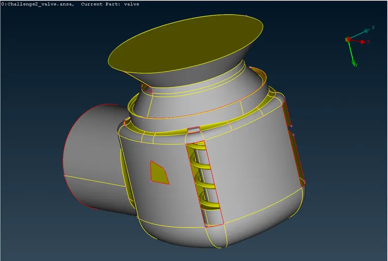
The Steps for topological cleaning up of the given model, PID assignments and surface meshing of the model:
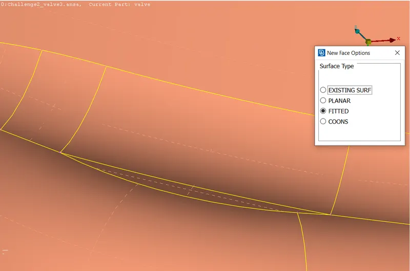
- To fill the holes in the exisintg surfaces, missing surfaces by using Topo>Faces>New command with various available new face options as exisitng surfaces, plannar, fitted and COONS accordingly. The following images describe the same.
1) Hole in the existing surface filled with existing surf option 2) Missing surfaces created with COONS option 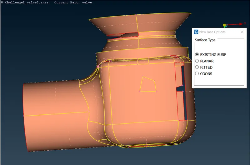
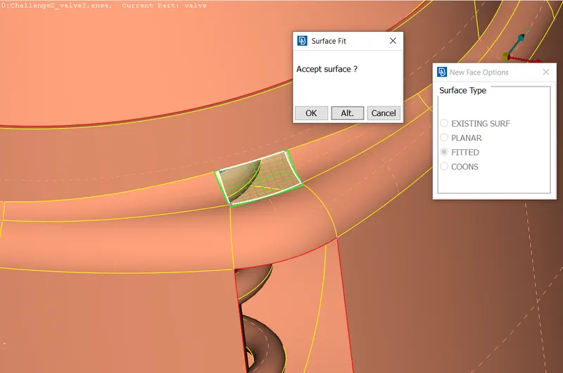
3) Missing surfaces created with Fitted option 4) Created surfaces in the earlier 3 steps 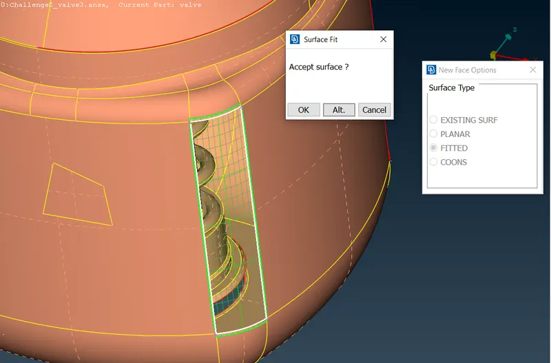
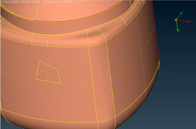
5) Missing surface with different curvatures created in steps : Step 1 with Fitted option 6) Missing surface with different curvatures created in steps :
Step 2 with Fitted option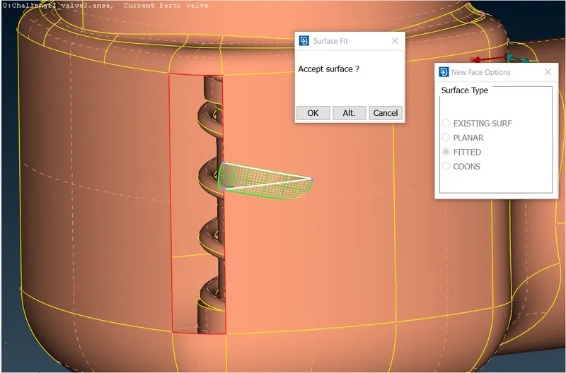
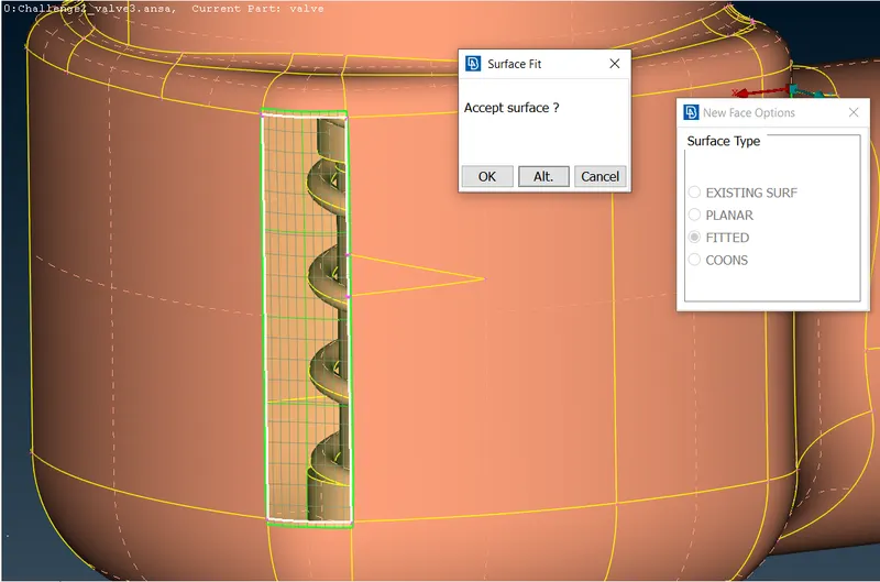
7) Missing surface with different curvatures created in steps : Surfaces from Step 1 & Step 2 8) Filling the holes or missing surfaces with Topo>CONs>Fill Hole command 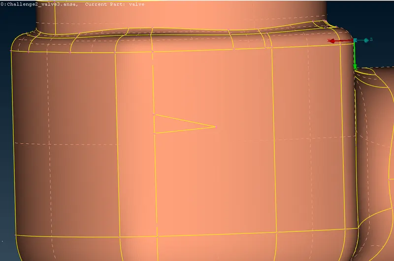
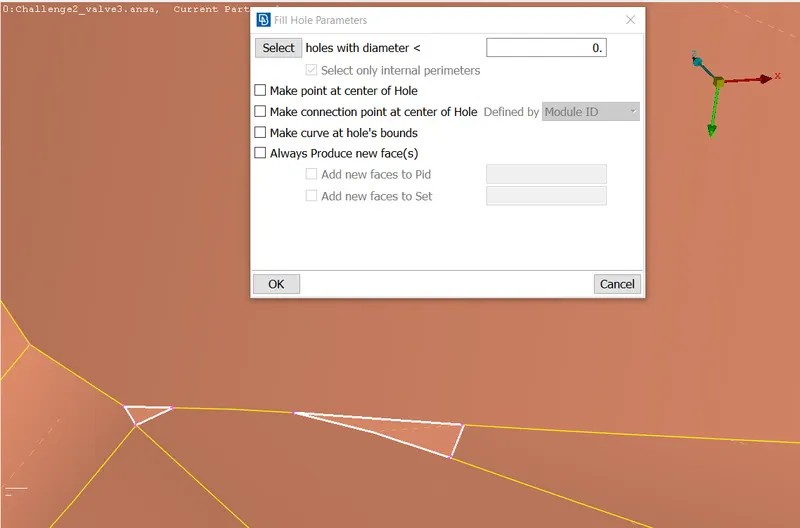
9) Filled the holes or missing surfaces with Topo>CONS>Fill Hole command 10) Filling the holes or missing surfaces with Topo>CONS>Fill Hole command: Error occured as unchecked as shown below 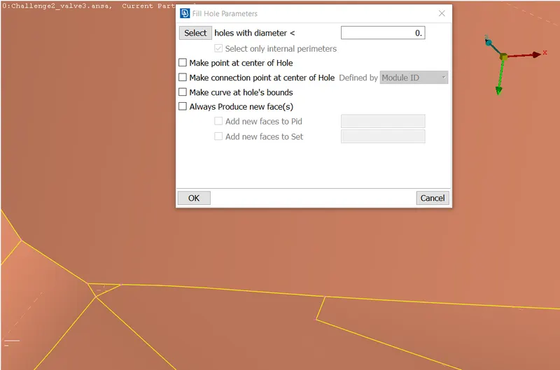
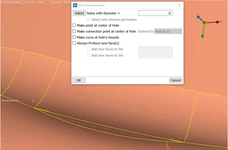
11) To remove the error from (10) - Creating the same Surface with fitted surface option 12) To remove the error from (10) - Created the same Surface with fitted surface option - No error observed 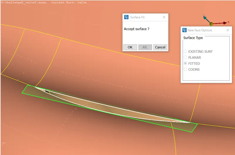
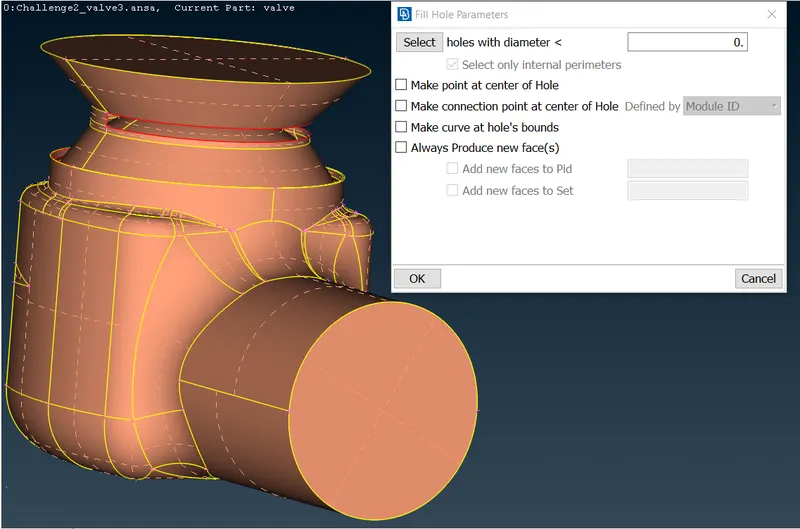
13) Surface Missing at the outlet is created using Topo>CONS>Fill Hole command 14) Surface Missing at the outlet is created using Topo>CONS>Fill Hole command- View after surface cration 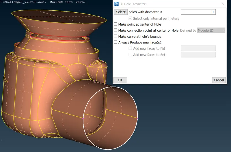
15) Curved Surfaces missing at the valve inlet created using COONS option- Surface 1 16) Curved Surfaces missing at the valve inlet created using COONS option- Surface 2 in wireframe mode for better visibility 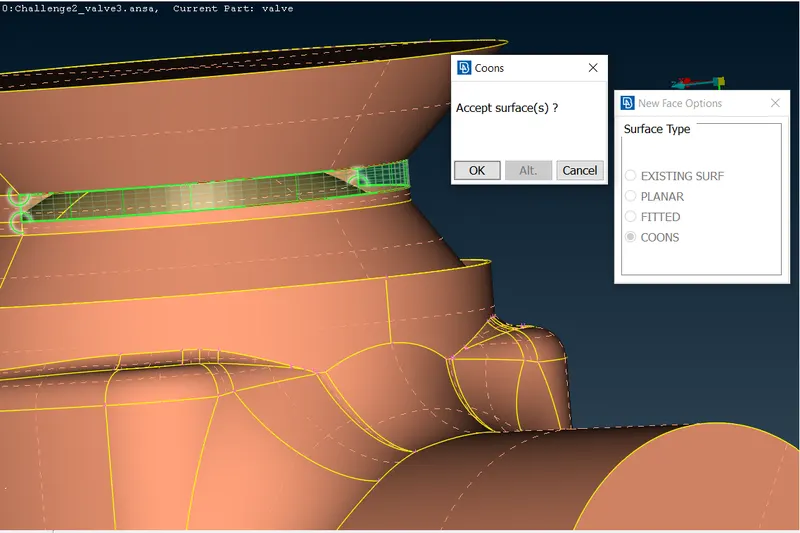
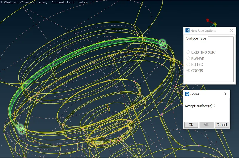
17) View of the surfaces created in (15) and (16) 18) Curved Surfaces missing at the bottom of the valve are created using COONS option - Surface 1 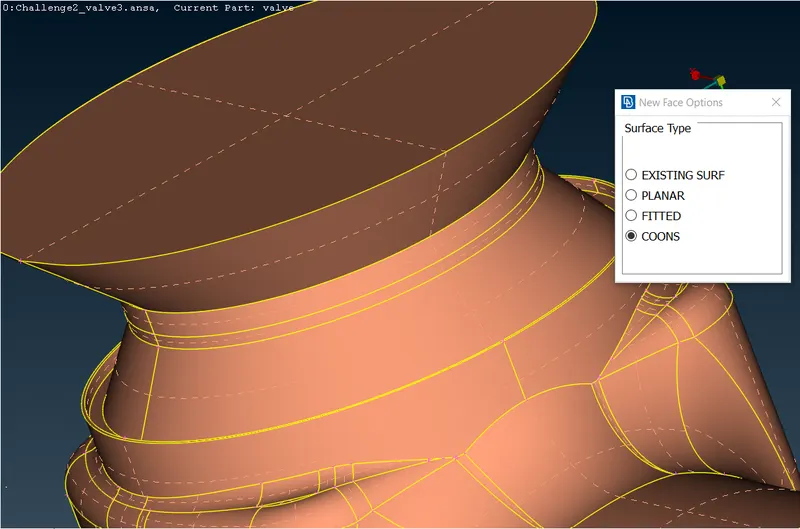
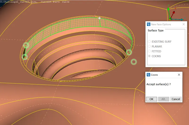
19) Curved Surfaces missing at the bottom of the valve are created using COONS option - Surface 2 20) View of the surfaces created in (18) and (19) 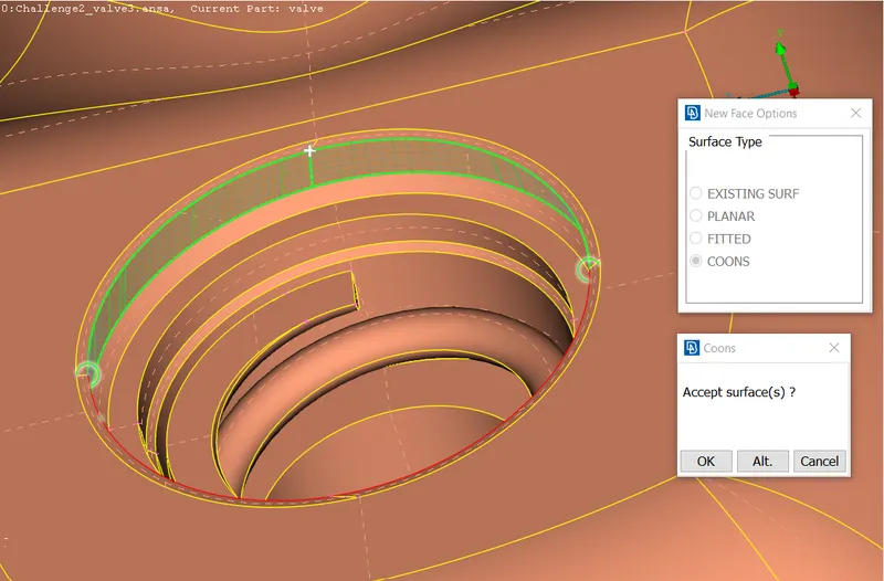
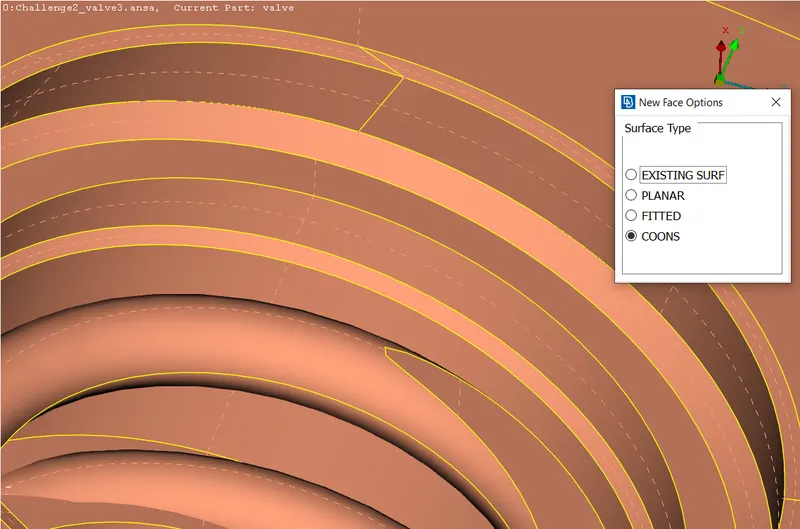
21) Creating the Bottom surface at the valve bottom to make valve body closed geometry using COONS option. 22) Final View of the Created Bottom surface with indication of presence of triple con 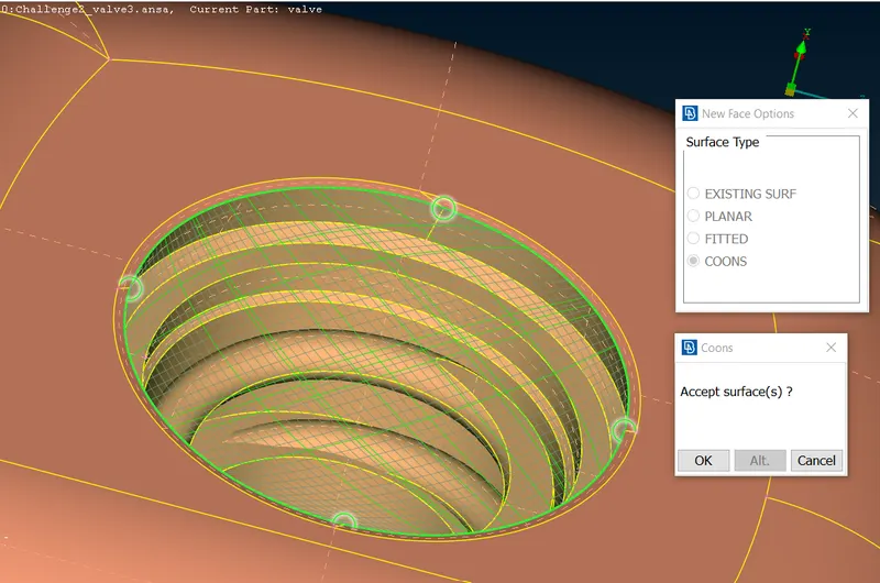
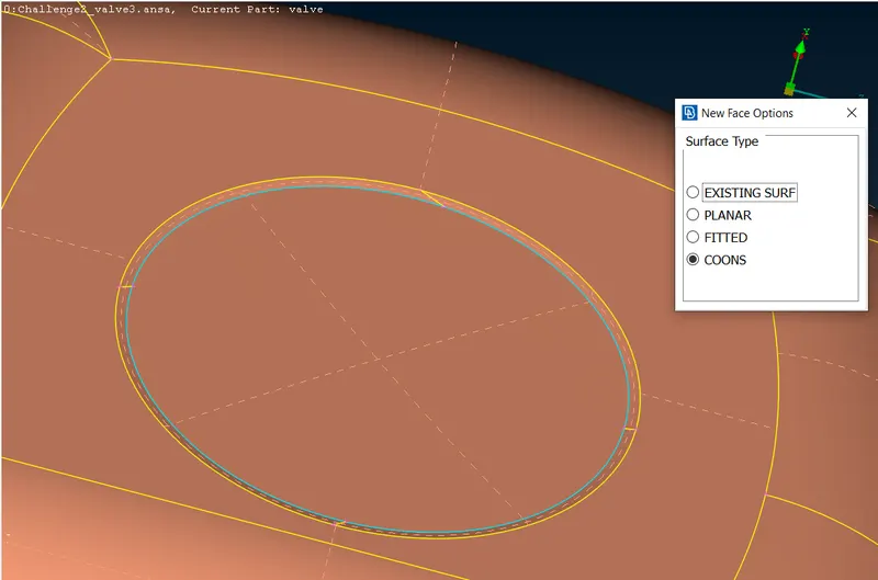
23) Examination of presence of single cons by activating cross hatch and deactivating double and triple cons:
No Single cons present (No red marking)24) Examination of presence of single cons by activating cross hatch and activating double and triple cons:
No Single cons present (No red marking), One triple con observed as expected.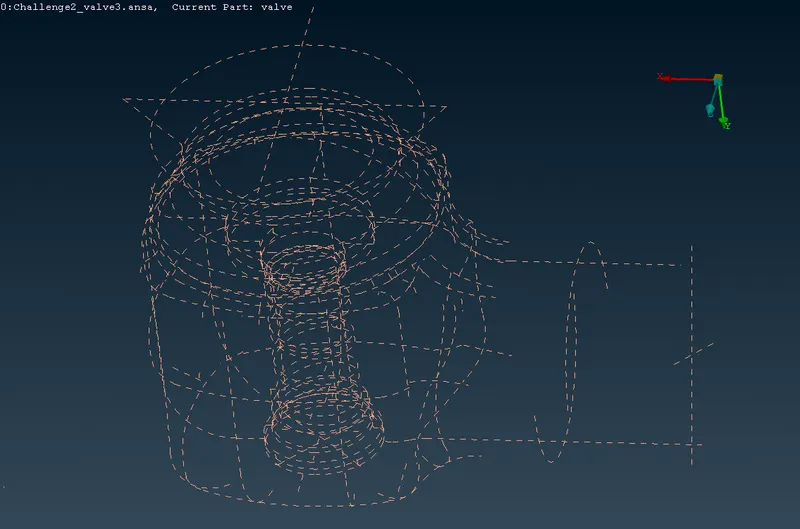
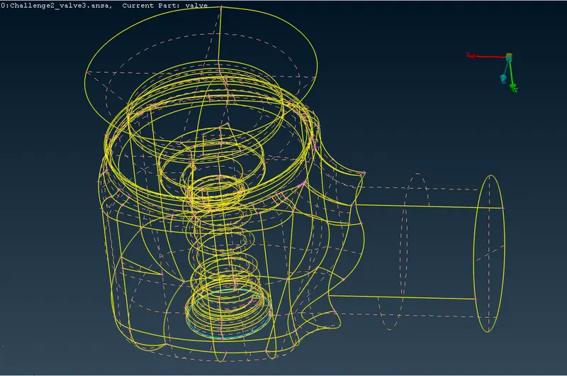
- To investigate the presence of triple con
1) Required surfaces are displayed using !Not boolean operation 2) Geometry has been checked using check command set : Step 1 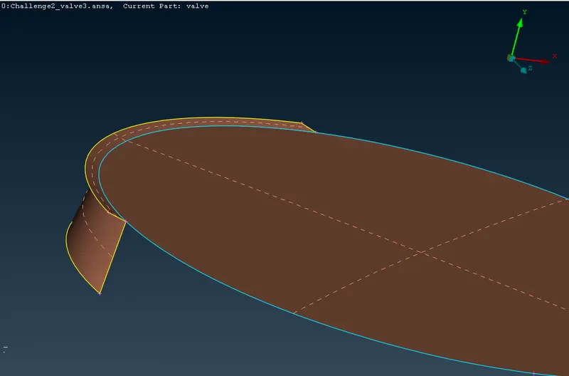
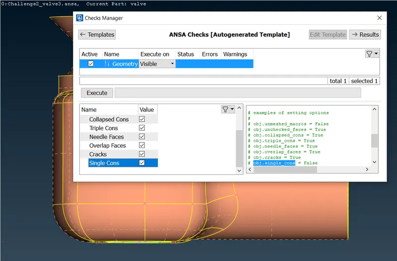
3) Geometry has been checked using check command set : Step 2 4) Conclusions after Investigation of triple con 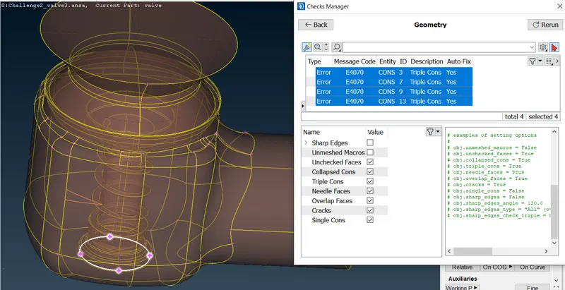
1) Three different sufaces share the comman edge so the triple con is formed.
2) All the three surfaces are required for further processing of the model.
3) So the esisting triple con is not an error.
- Deleting the unwanted or smaller double cons with Topo>CONS>cut>right click
1) Double Cons created after filling the hole in the existing surface 2) Delecting the Double Cons created after filling the hole in the existing surface as those are not required - Step 1 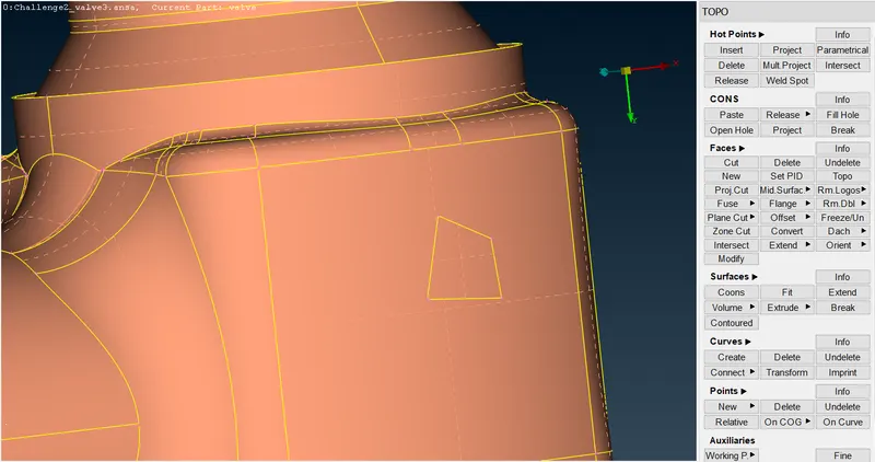
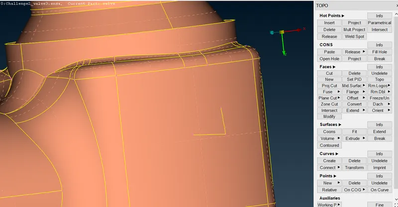
3) Delecting the Double Cons created after filling the hole in the existing surface as those are not required - Step 2
4) Double Cons created after filling the hole in the surface with different curvatures 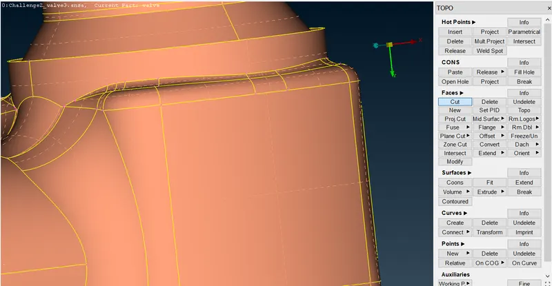
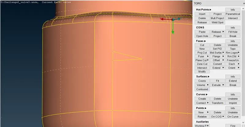
5) Deleting the Double Cons created after filling the hole in the surface with different curvatures 6) Delecting the Double Cons which are very small and insignificant.
History of them can be seen as orange colour cons.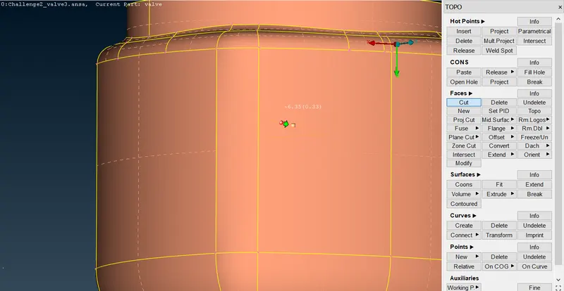
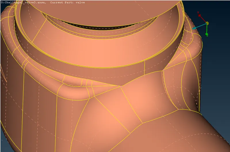
- Once again the model is tested for presence of any single con. But no single con has been observed.
- Thus the Properties manager has been opened and new PIDs are created for the model,which are yet to be assigned.
Here Colour Scheme for PIDs may look dissimilar or confusing, as it has been changed for time to time for the convinience. 1) New PIDs are created with appropriate names along with
parent PID-36.2) Assigning surface to the inlet PID-35. 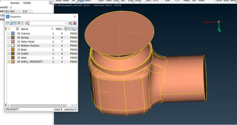
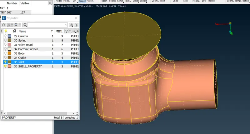
3) Assigning surface to the Outlet PID-34. 4) Assigning surface to the Body PID-33. 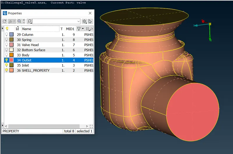
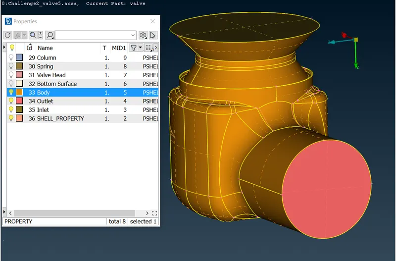
5) Assigning surface to the Bottom Surface PID-32. PID for Body,
Outlet and Inlet are hidden.6) Assigning surface to the Valve Head PID-31. PID for Body,
Outlet, Inlet and Bottom Surface are hidden.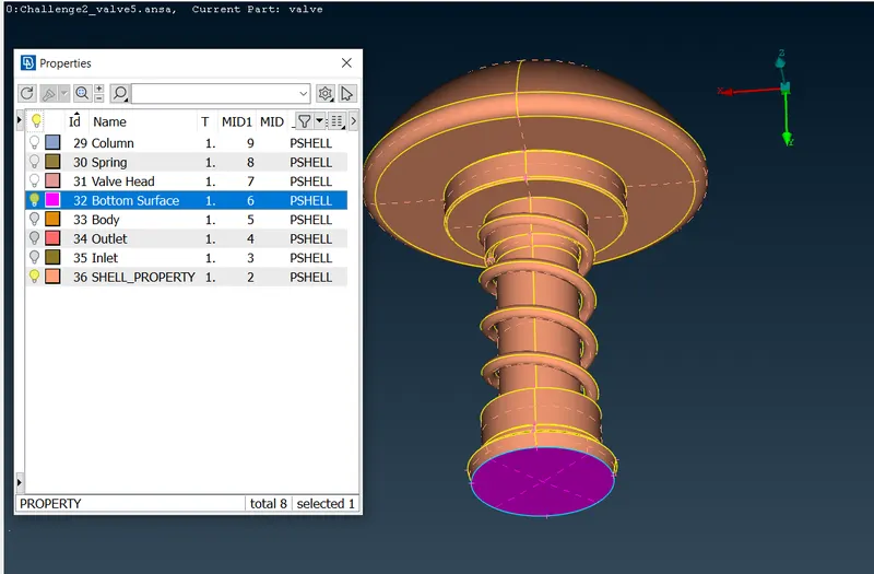
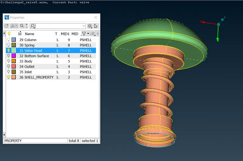
7) Assigning surface to the Spring PID-30. PID for Body,
Outlet, Inlet, Bottom Surface and Vlave Head are hidden.8) Assigning surface to the Column PID-29. PID for Body,
Outlet, Inlet, Bottom Surface and Spring are hidden.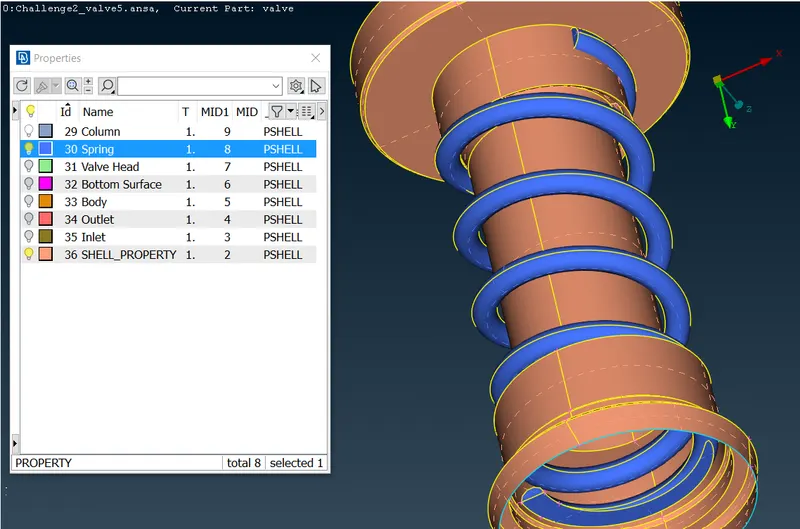
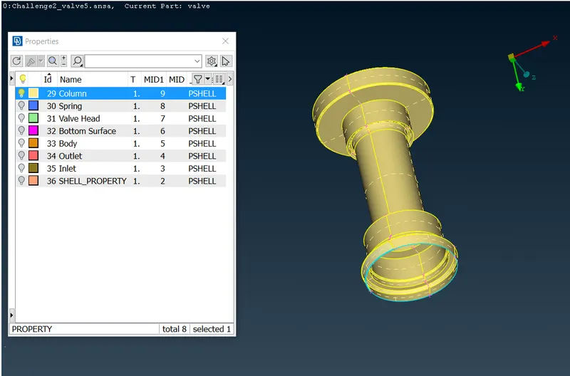
9) Inner Valve assembly after assigning all of the PIDs 10) Whole valve model after assigning all of the PIDs 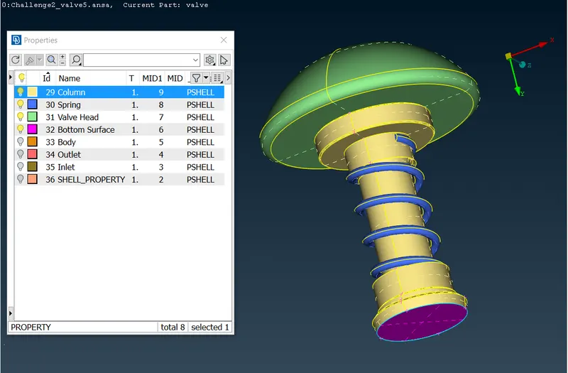
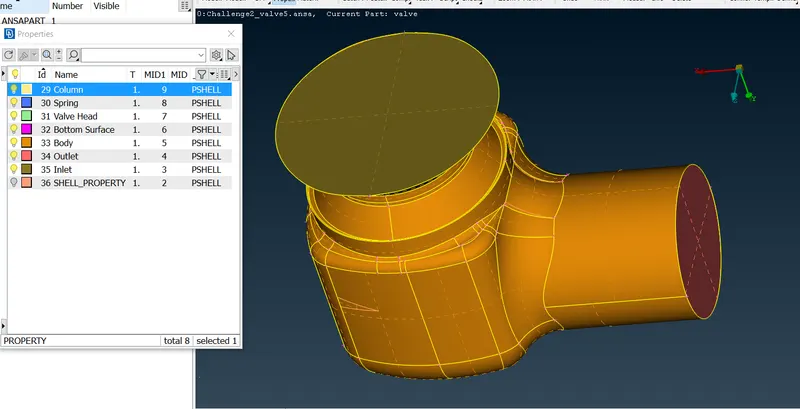
- Now Parent PID do not have any assigned surface thus after turning on also it is not showing any surface.
While deleting it the errors have been thrown regarding as it cannot be deleted as already some surfaces have been deleted from it.
Thus the respective PID has been compressed. The supporting screenshots are as follows.
1) The PID-36 has been picked up but no surface shown up. 2) The PID-36: show only option selected but surface shown up 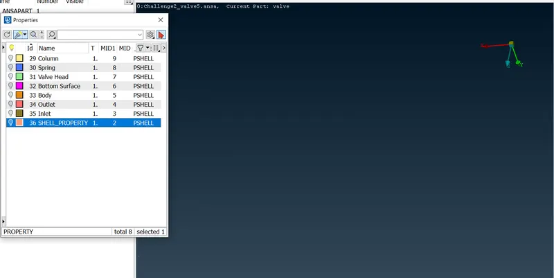
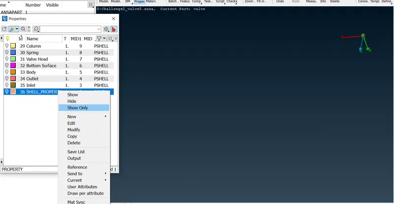
3) The PID-36 has been compressed as error occured while deleting it. 4) The list of PIDs after deleting the PID-36. 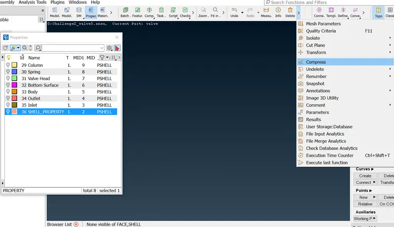
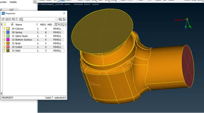
5) Showing the Column PID-29 in whole assembly. 6) Showing the Spring PID-30 in whole assembly. 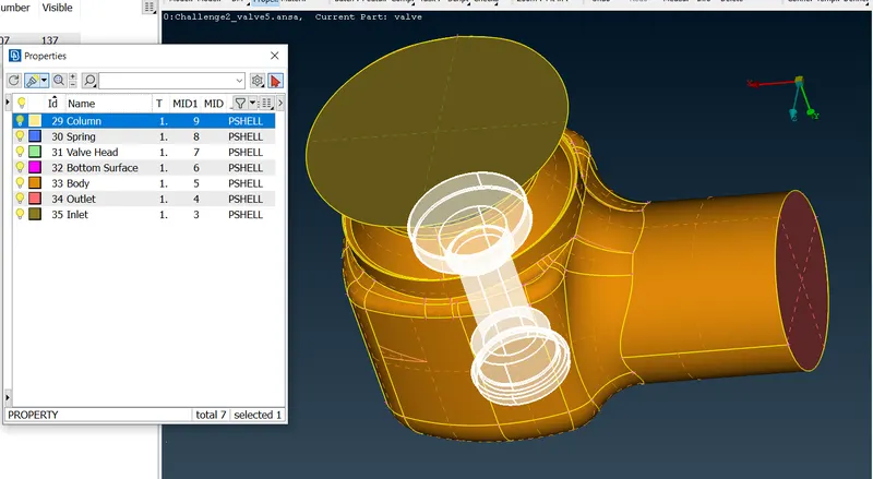
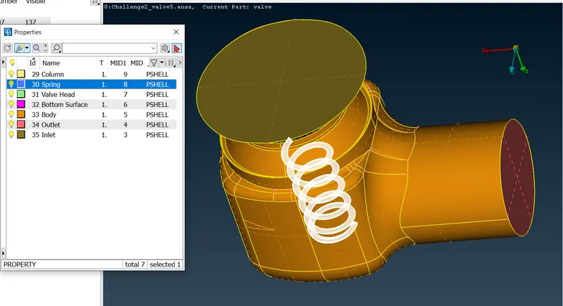
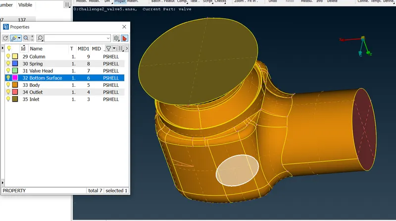
7) Showing the Column Valve Head PID-31 in whole assembly. 8) Showing the Bottom Surface PID-32 in whole assembly. 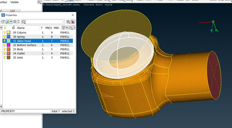
9) Showing the Body PID-33 in whole assembly. 10) Showing the Outlet PID-34 in whole assembly. 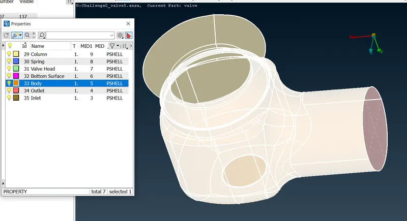
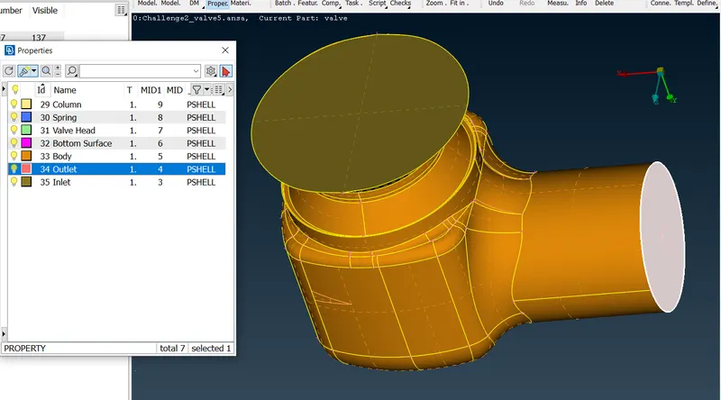
11) Showing the Inlet PID-35 in whole assembly. 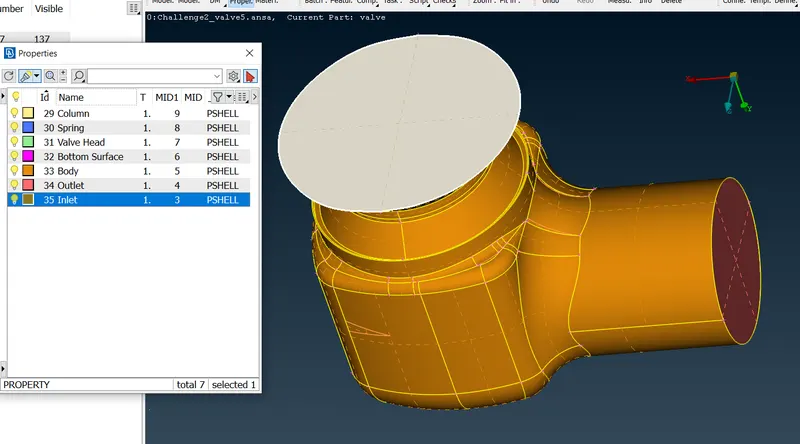
- Three different models have been created in similar way as explained above with different target lengths and element type as tria
for their surface meshing. - The model with target length=5 mm and element type as tria has been meshed accordingly.
The steps for meshing as follows and surface mesh of the different components have also been presented here.
1) Setting up the Mesh Parameters for target length=5 mm and
tria as element type.2) Setting up the Quality Criteria for target length=5 mm. 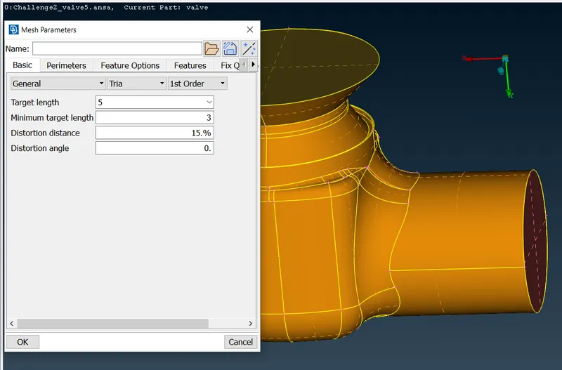
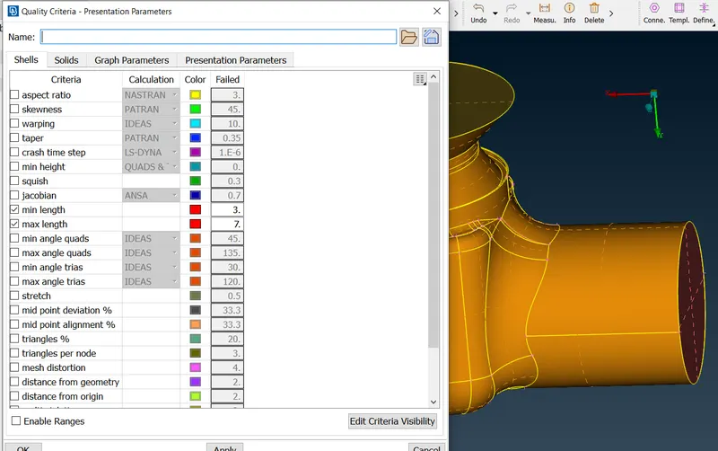
3) Setting up the Perimeter under
Mesh>Perimeters>Length>Perimeters for whole assembly
as 5 mm.4) Setting up the Perimeter under
Mesh>Perimeters>Length>Macros for whole assembly
as 5 mm.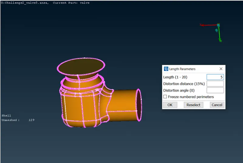
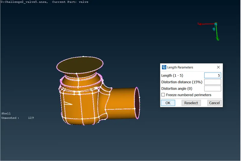
5) The whole assembly have been surface meshed using
Mesh>Mesh Generation>Spot Mesh command over assembly.6) The Generated surface mesh is as shown below. 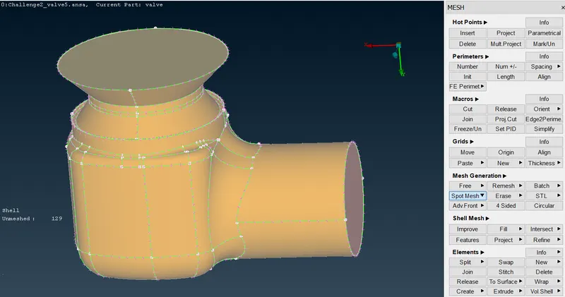
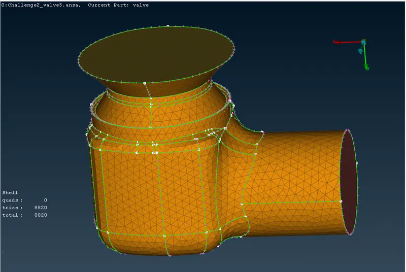
7) Mesh at Inlet surface. 8) Mesh at Outlet surface 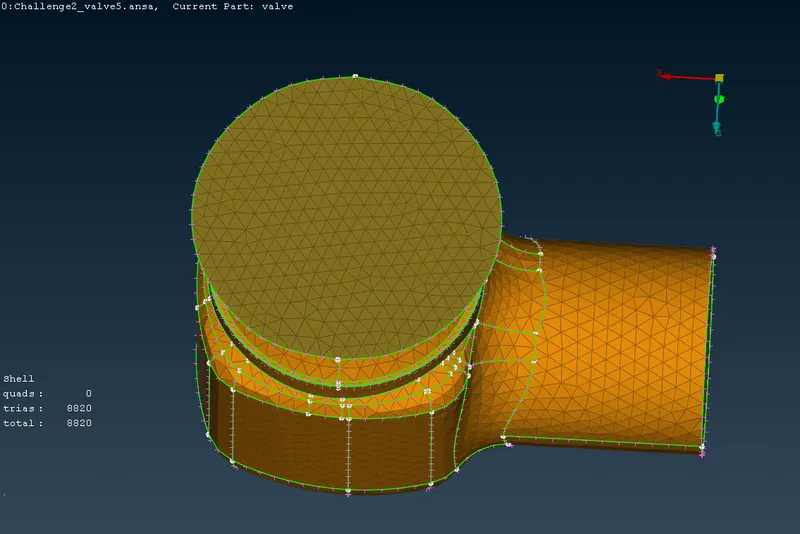
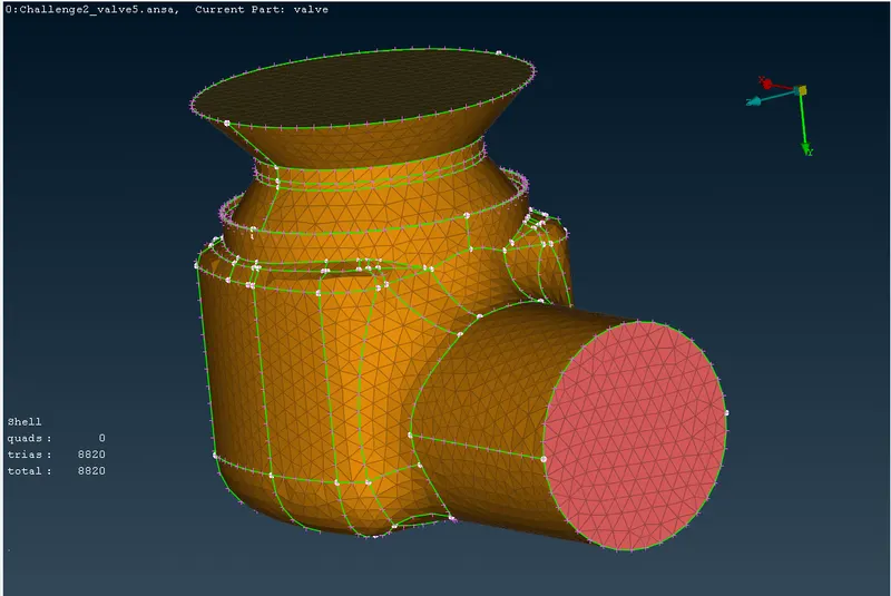
9) Mesh on Body 10) Mesh at Bottom surface 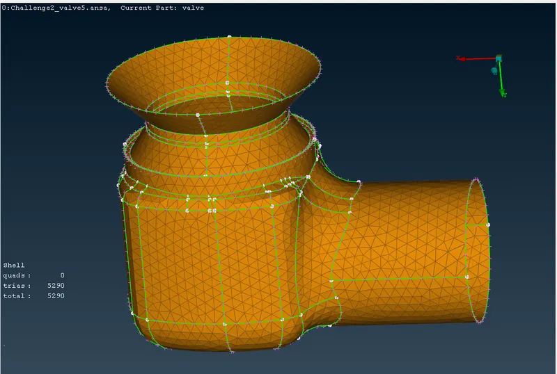
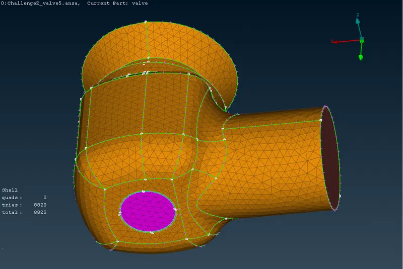
11) Mesh on inner Valve assembly. 12) Mesh on Valve head. 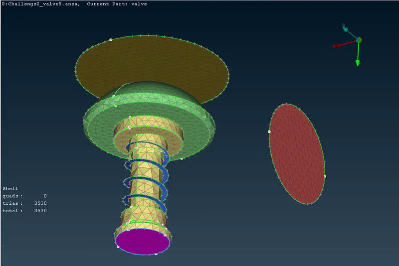
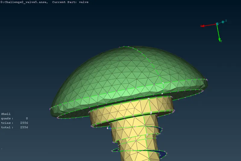
13) Mesh on Spring with Spering dia measurement. 14) Observations on Meshing with target length =5 mm. 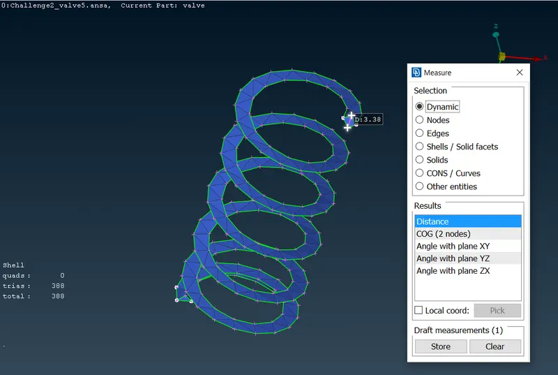
1) As target length =5 mm the surface features with length less than 5 mm are not captured with details on whole assembly.
2) The curved surface of the valve head have not been captured clearly as curvature is less than 5 mm.
3) The most importantly the spring surface have not been capture correctly as the spring diameter is less than 5 mm (i.e. 3.4 mm). Thus seems like a curved plane.
4) These can be observed in above supporting images.
- The model with target length=3 mm and element type as tria has been meshed accordingly.
The steps for meshing as follows and surface mesh of the different components have also been presented here.
The colour scheme is not consistent as the different models have been used which are processed seperately from initial stages.
1) Setting up the Mesh Parameters for target length=3 mm and
tria as element type.2) Setting up the Quality Criteria for target length=3 mm. 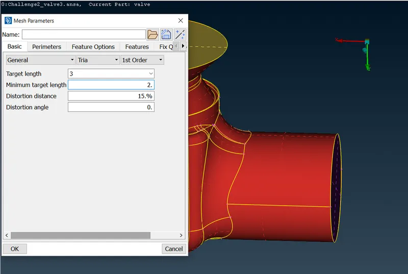
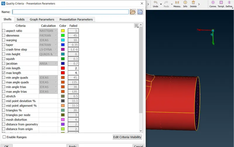
3) Setting up the Perimeter under
Mesh>Perimeters>Length>Perimeters for whole assembly
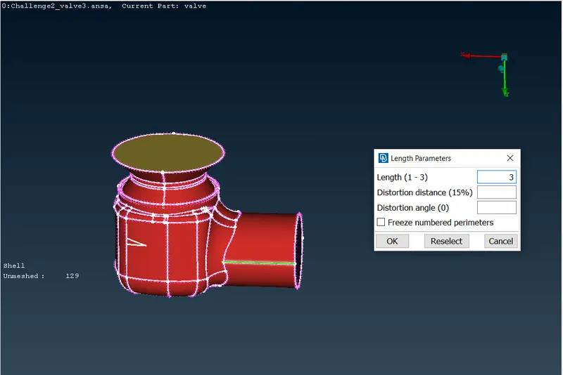
as 3 mm.4) Setting up the Perimeter under
Mesh>Perimeters>Length>Macros for whole assembly
as 3 mm.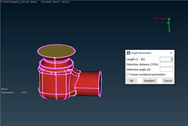
5) The whole assembly have been surface meshed using
Mesh>Mesh Generation>Spot Mesh command over assembly.6) The Generated surface mesh is as shown below. 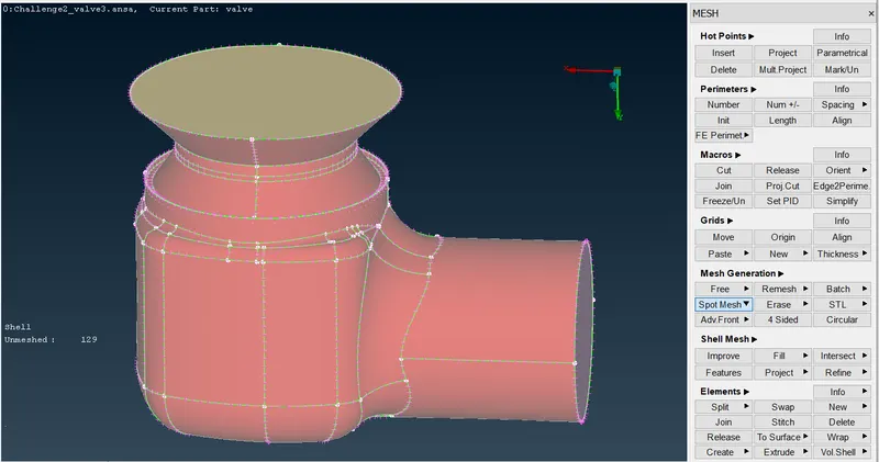
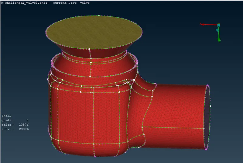
7) Mesh at Inlet surface. 8) Mesh at Outlet surface 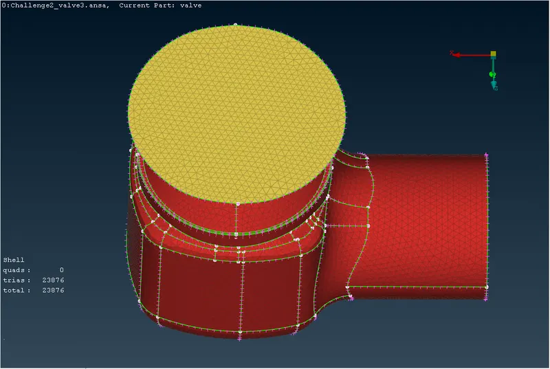
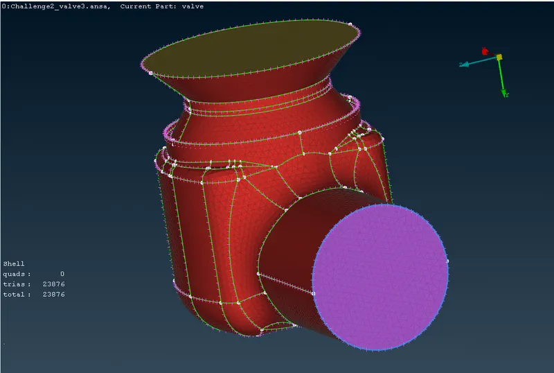
9) Mesh on Body 10) Mesh at Bottom surface 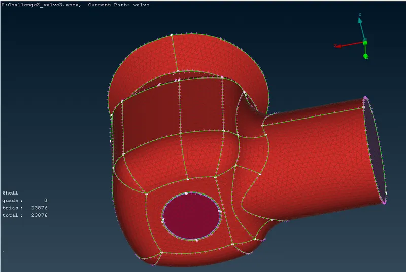
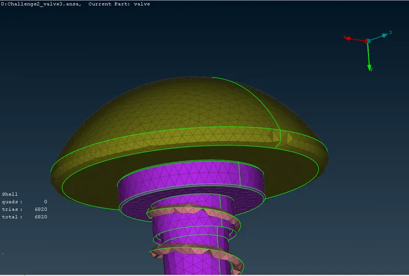
11) Mesh on inner Valve assembly. 12) Mesh on Valve head. 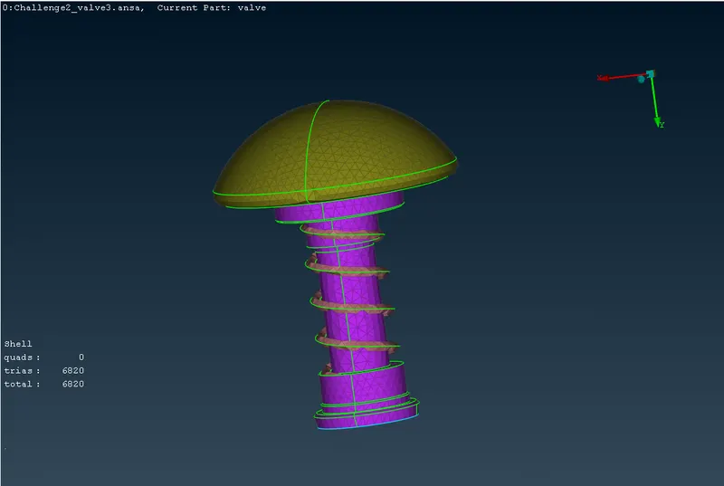
13) Mesh on Spring with Spering dia measurement. 14) Observations on Meshing with target length =3 mm. 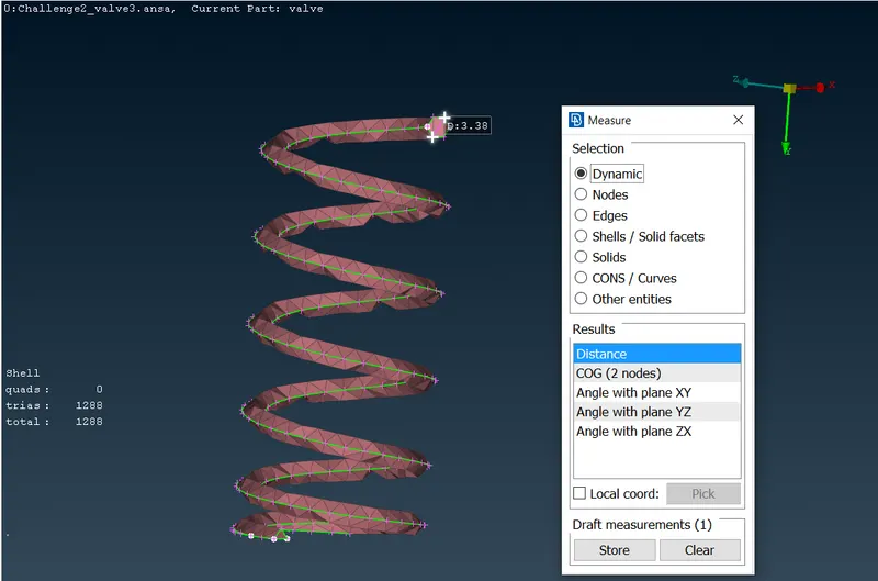
1) As target length =3 mm the surface features with length less than 3 mm are not captured with details on whole assembly.
2) The curved surface of the valve head have been captured more clearly as curvature is greater than of equal to 3 mm.
3) The most importantly the spring surface have not been capture correctly as the spring diameter is slightly greater than 3 mm (i.e. 3.4 mm). Thus it is showing up the irregular surface.
4) These can be observed in above supporting images.
- The model with target length=1 mm and element type as tria has been meshed accordingly.
The steps for meshing as follows and surface mesh of the different components have also been presented here.
The colour scheme is not consistent as the different models have been used which are processed seperately from initial stages.
1) Setting up the Mesh Parameters for target length=1 mm and
tria as element type.2) Setting up the Quality Criteria for target length=1 mm. 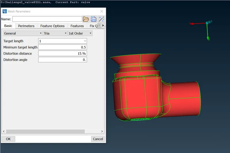
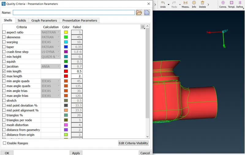
3) Setting up the Perimeter under
Mesh>Perimeters>Length>Perimeters for whole assembly
as 1 mm.4) Setting up the Perimeter under
Mesh>Perimeters>Length>Macros for whole assembly
as 1 mm.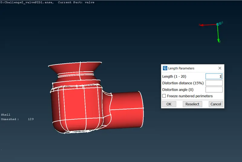
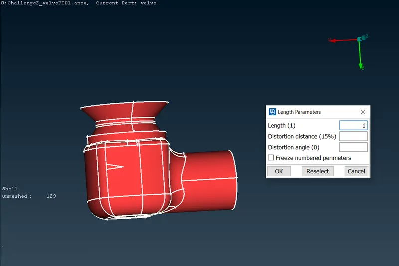
5) The whole assembly have been surface meshed using
Mesh>Mesh Generation>Spot Mesh command over assembly.6) The Generated surface mesh is as shown below. 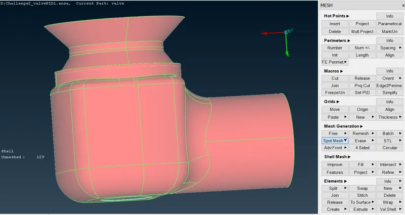
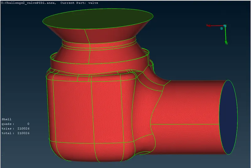
7) Mesh at Inlet surface. 8) Mesh at Outlet surface 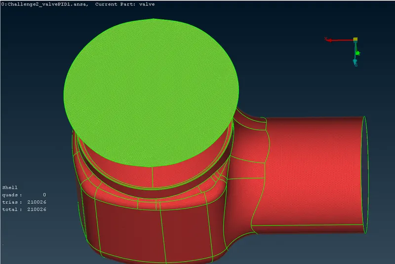
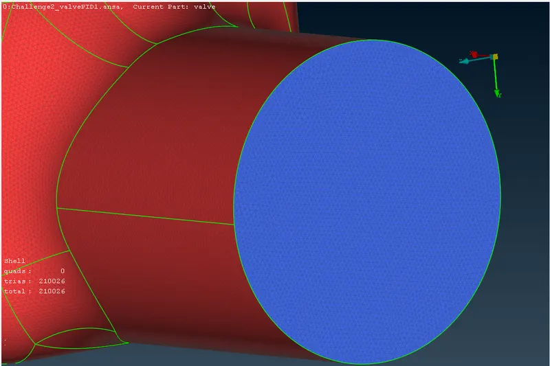
9) Mesh on Body 10) Mesh at Bottom surface 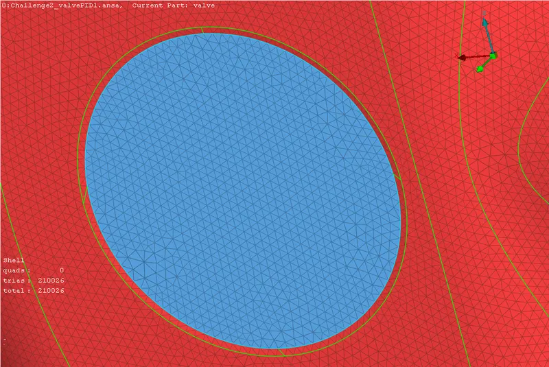
11) Mesh on inner Valve assembly. 12) Mesh on Valve head. 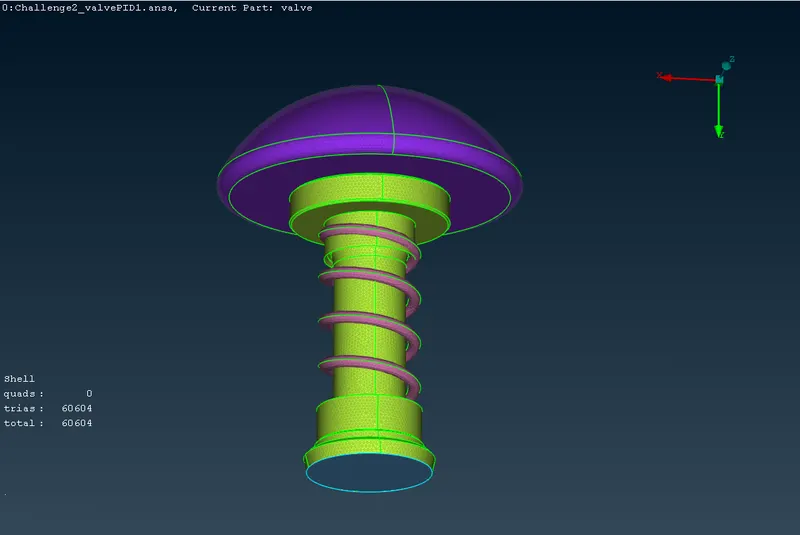
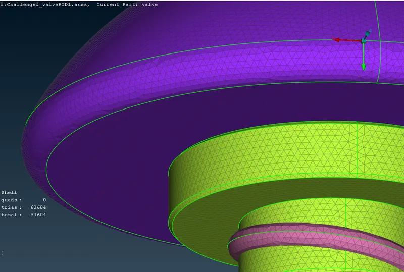
13) Mesh on Spring with Spering dia measurement. 14) Observations on Meshing with target length =1 mm. 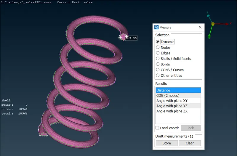
1) As target length =1 mm the surface features are captured with great accuracy and smoothly on whole assembly.
2) The curved surface of the valve head have been captured smoothly and neatly as curvature is greater than 1 mm.
3) The most importantly the spring surface have been capture correctly as the spring diameter is greater than 1 mm. Thus now spring surface looks like smooth surfaces.
4) These can be observed in above supporting images.
- Thus surface of the given geometry have been meshed with 3 different target length with tria as element type. The .ansa files of above three models have been saved and attached herewith for the reference.
Conclusions:
- Thus the given model have been meshed for three different target lengths as 1 mm, 3 mm and 5 mm successfully with given set of precedure.
- The mesh with target length=5 mm is not smooth and accurate as it fails to capture minute surface details with length less than 5 mm. The spring surfaces have not been captured smoothly. Also the curvature of the valve head have not been captured smoothly and neatly. These can be observed in corresponding images presented above.
- The mesh with target length=3 mm is also failed to capture the spring surface smoothly but was able to capture valve head curvature more smoothly than the mesh with target length= 5 mm.
- The mesh with target length= 1mm was able to capture all the surface features with accepteable accuracy. The spring surface and curvature at valve head have been captured smoothly. As the target length is small enough to capture the majority of the surface features.
- Also the number mesh elements should increase by the factor of square of the ratios of the target lengths as target length decreases which is justified with the greater accuracy here as the elements are increasing from 8820 to 23786 from target length=5 mm to 3 mm, which is equals to 2.6968 which approximates to `(frac{5}{3})^2 = 2.78` and similarly,
the elements are increasing from 8820 to 210026 from target length=5 mm to 1 mm, which is equals to 23.81 which approximates to `(frac{5}{1})^2 = 25`.