Week 5 Challenge : Surface wrap on Automotive Assembly
Aim: To perform surface wrap on automotive assembly.
For the given models,
To check for the geometrical errors and to delete surfaces which are unwanted for Surface wrap as shown in the videos.
After clearing geometry,merge all 3 models to perform surface wrap.
Target length for Wrap = 3 mm.
Steps to perform surface wrap on automotive assembly:
- Geometric clean up of Engine model:
1) Isometric view of the engine model with extra surfaces and overlapped surfaces on main geometry. 2) Isometric view from rear angle of the engine model with extra surfaces and overlapped surfaces along with belt and pully drives on main geometry. 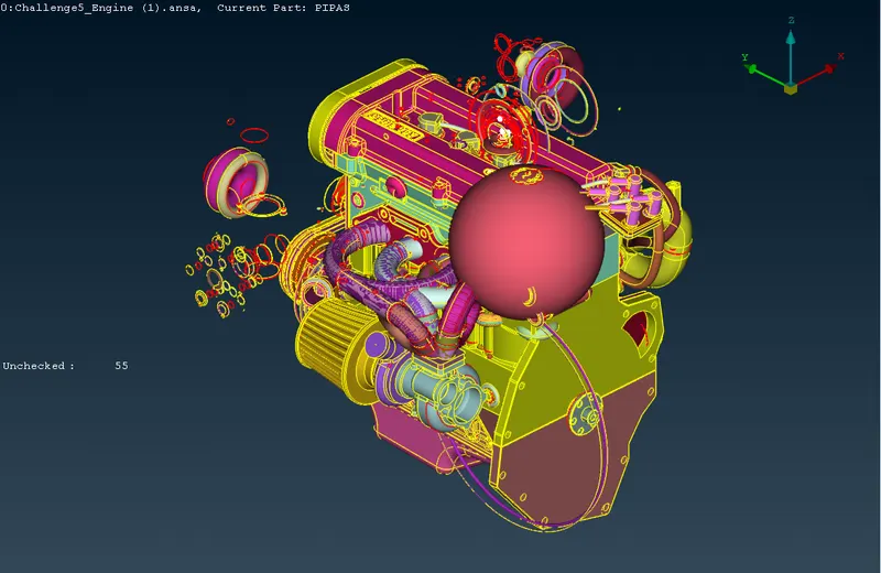
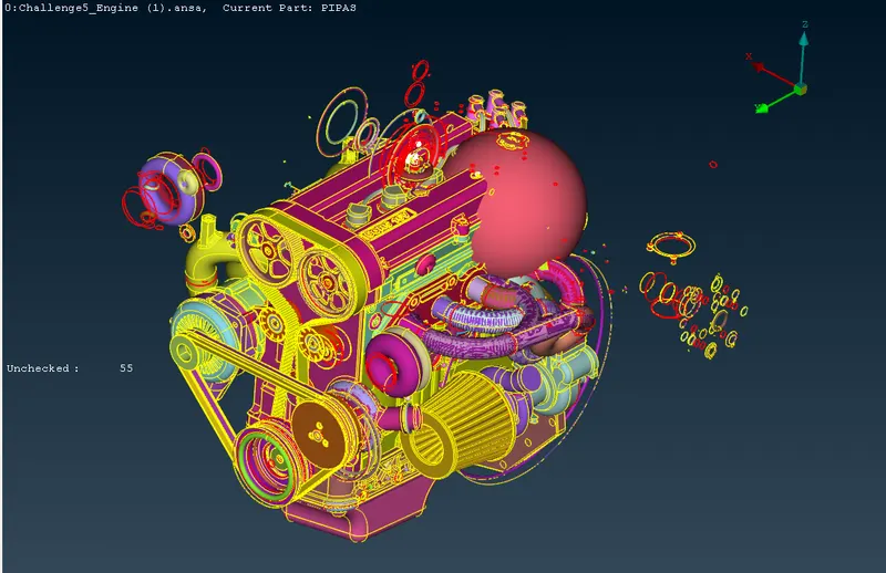
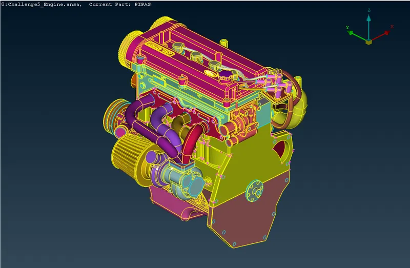
3) Side view of the main engine geometry showing extra surfaces. 4) Isometric view of the engine model after geometric clean up. The internal surfaces showing some triple cons are acceptable here as we are going do the surface wrap which will need external surfaces only. Same is applicable to gearbox and transimission assembly. 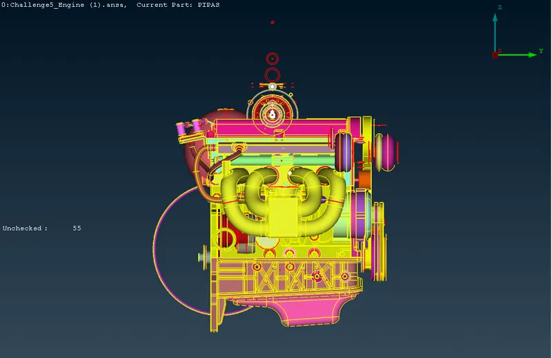
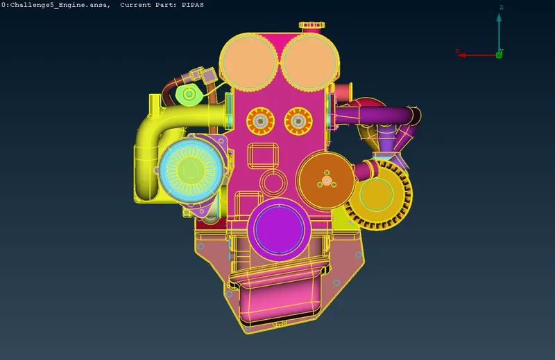
5) The front view of engine model after gometrical clean up showing extra surfaces created over holes to avoid problem while surface wrapping. 6) The rear view of engine model after gometrical clean up showing extra surfaces created over holes and removed belts to avoid problem while surface wrapping. 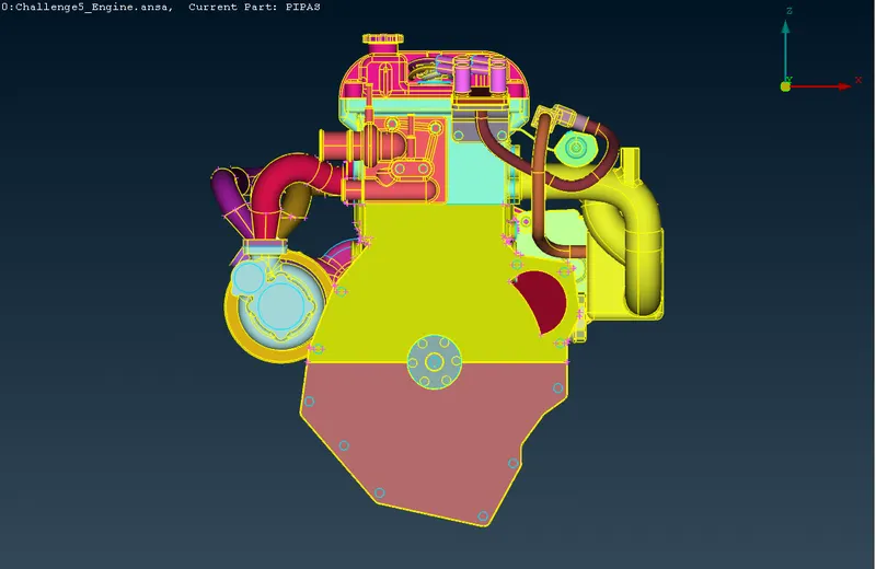
7) The side view of engine model after gometrical clean up showing extra surfaces created over holes to avoid problem while surface wrapping. 8) The top view of engine model after gometrical clean up showing extra surfaces created over holes to avoid problem while surface wrapping. 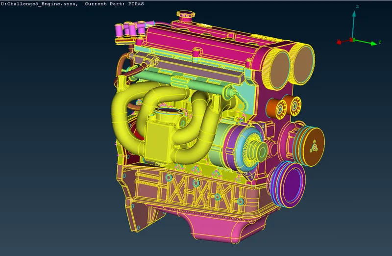
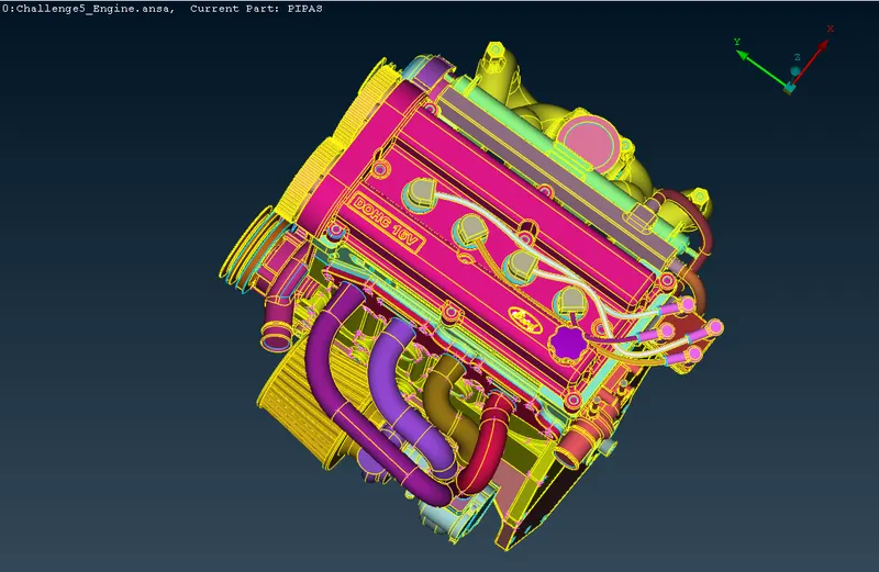
9) The view of engine model after gometrical clean up showing extra surfaces created over holes and removed belts from the drive to avoid problem while surface wrapping. 10) The view of engine model after gometrical clean up showing extra surfaces created over holes to avoid problem while surface wrapping. 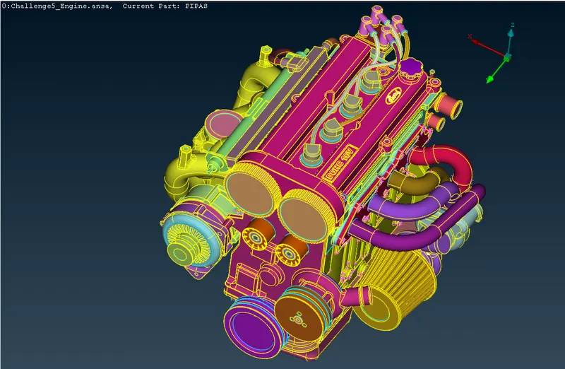
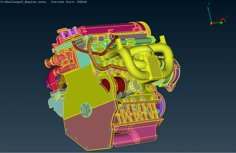
- Geometric clean up of Gearbox model:
1) The isometric view of the gearbox assembly showing extra surfaces and triple cons. 2) The isometric view of the gearbox assembly from rear angel showing triple cons. 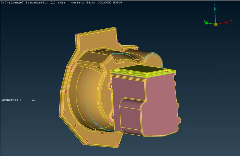
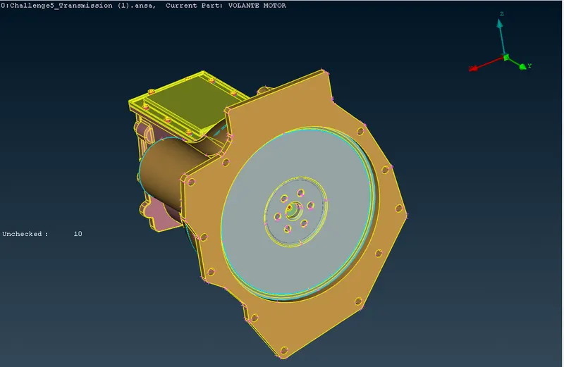
3) The side view of the gearbox assembly showing extra surfaces and triple cons. 4) The side view of the gearbox assembly showing extra surfaces and triple cons. 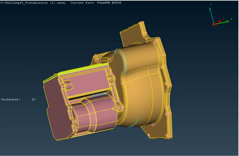
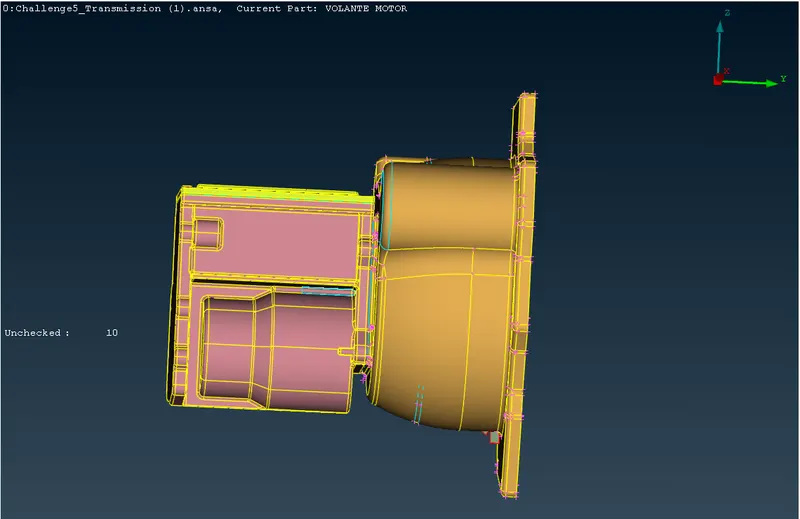
5) The isometric view of the gearbox assembly showing after cleaning up the extra surfaces and triple cons. Extra sufaces created to fill holes. 6) The view of the gearbox assembly after geometric clean up showing the extra surfaces created. 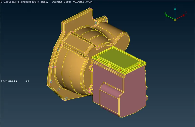
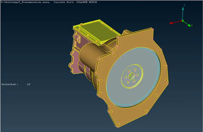
7) The side view of the cleaned gearbox assembly. 8) The side view of the gearbox assembly showing extra sufaces created on the holes. 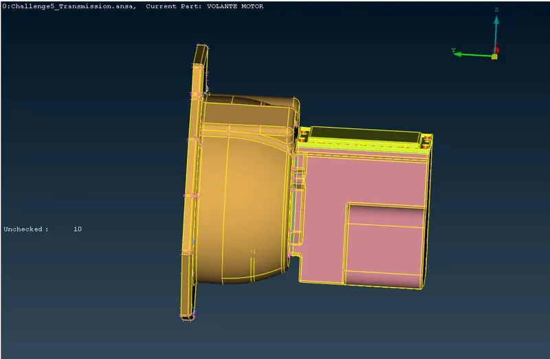
- Geometric clean up of Transmission model:
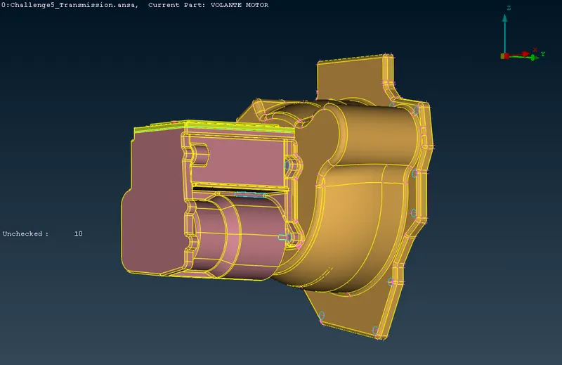
1) Isomteric view of the transmission assembly showing its external features. 2) Another view of the transmission assembly showing its external features. 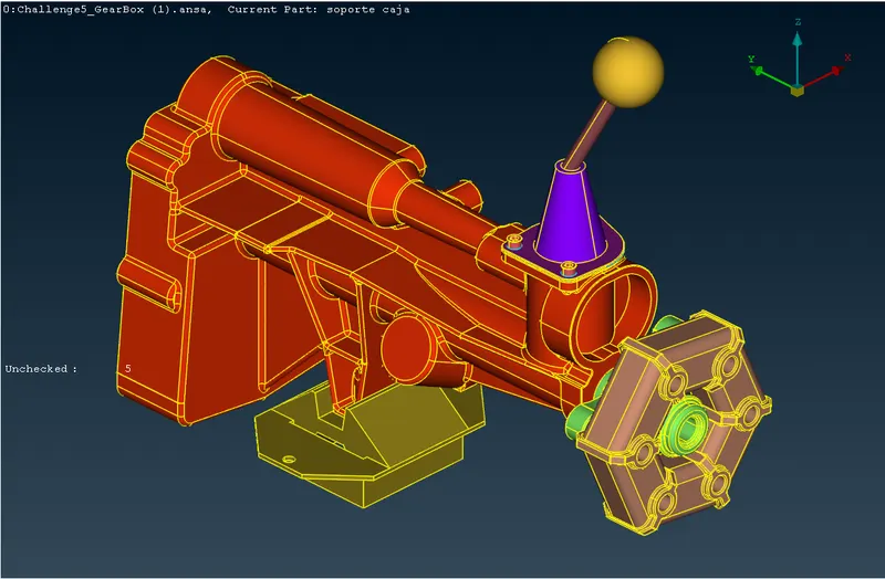
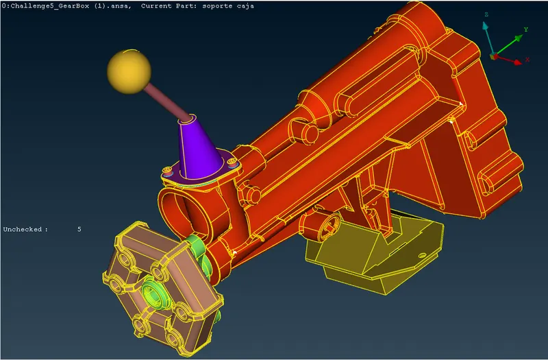
3) The view of transmission assembly showing the places where we need to creat extra surfaces avoid dents in the surface wrap. 4) The view of transmission assembly showing the places where we need to creat extra surfaces avoid dents in the surface wrap. 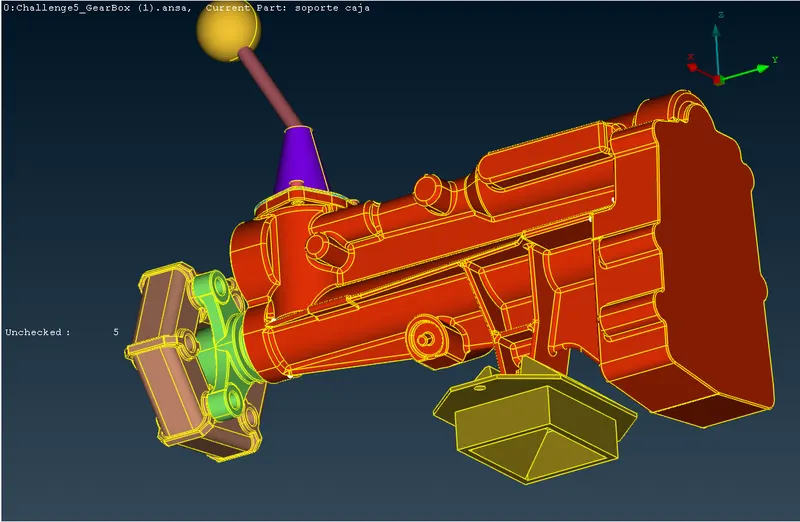
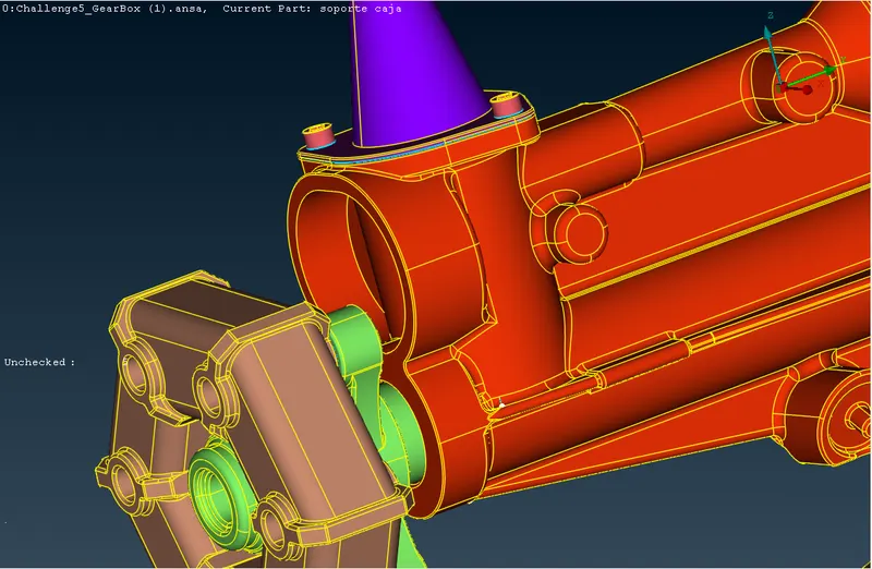
5) The isometric view of the transmission assembly after geometric clean up. 6) The view of the transmission assembly after geometric clean up. 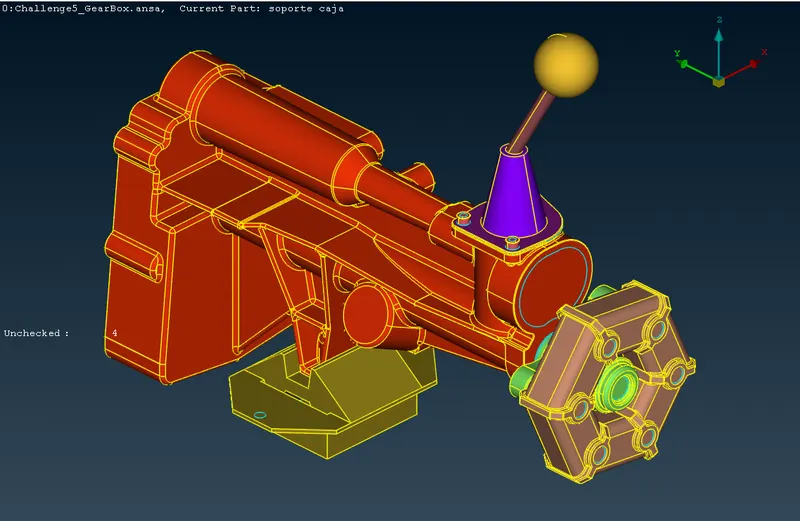
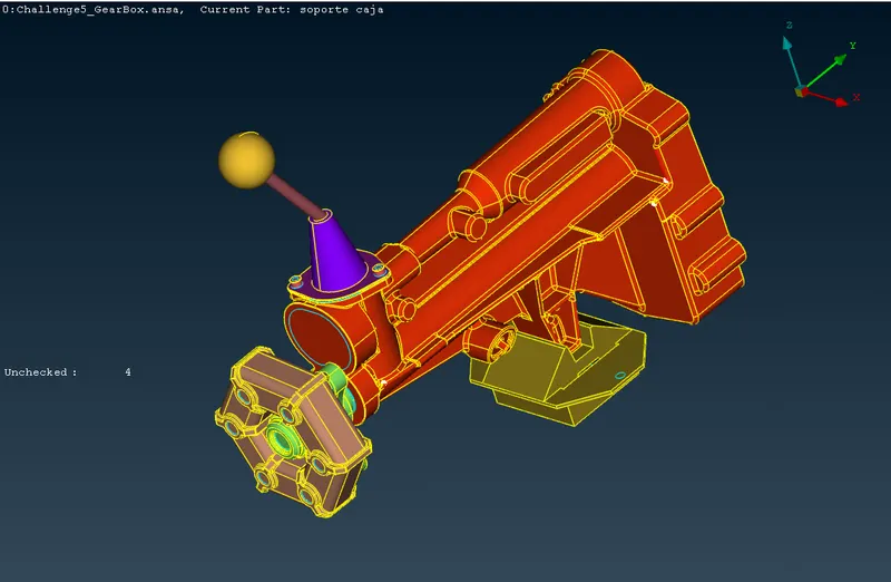
7) The view of the transmission assembly after geometric clean up and extra surfaces created on the holes. 8) The view of the transmission assembly after geometric clean up and created extra surfaces after filling the required holes. 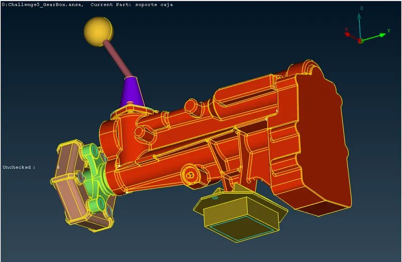

- Geometrical merging of the Gearbox and Transmission models with Engine model:
1) To merge the gearbox and transmission assembly into engine assembly go to file menu and clicking on the merge option into it. 2) Then selecting the gearbox and transmission assembly model files to merge into the engine assembly model. 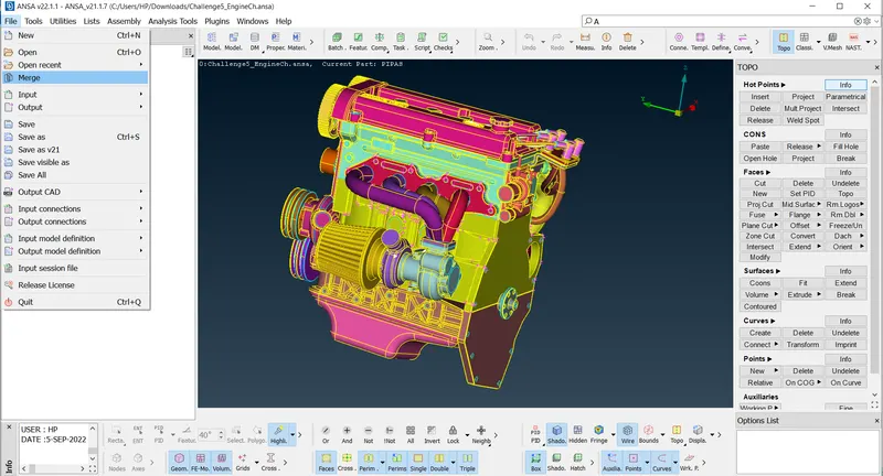
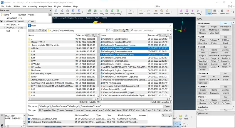
3) Then checking the right merge parameters and clicking OK. 4) The gearbox and transmission assemblies are merged with the engine assembly model giving some warning messages but as errors and warnings are zero so it can be neglected and closed. 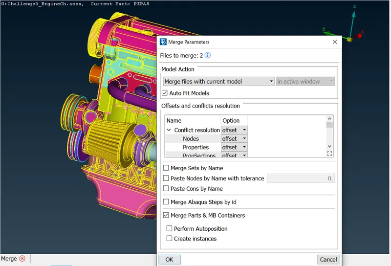
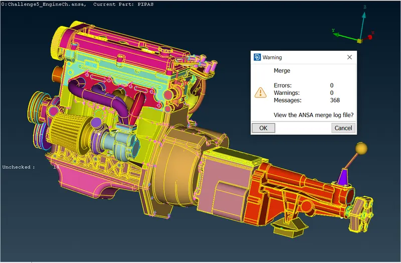
5) The view of the merged assemblies. 6) The close view of the connection of the gearbox and transmission assembly. 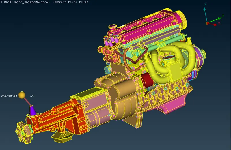
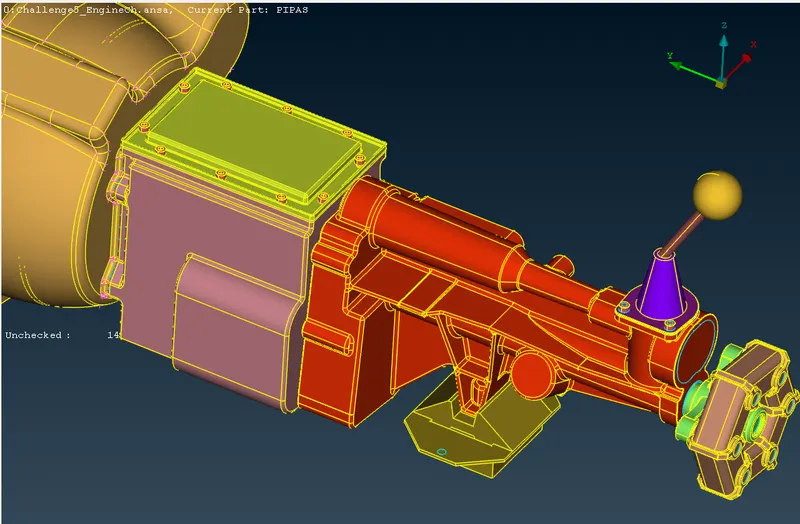
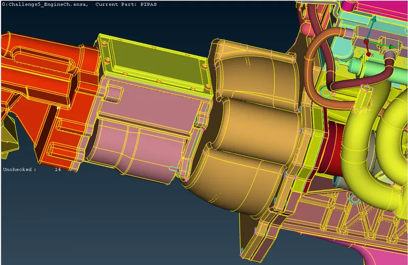
7) The close view of the connection of engine and gearbox assembly and measurement of the gap between them which comes to 3.61 mm. 8) The close view of both connection planes. 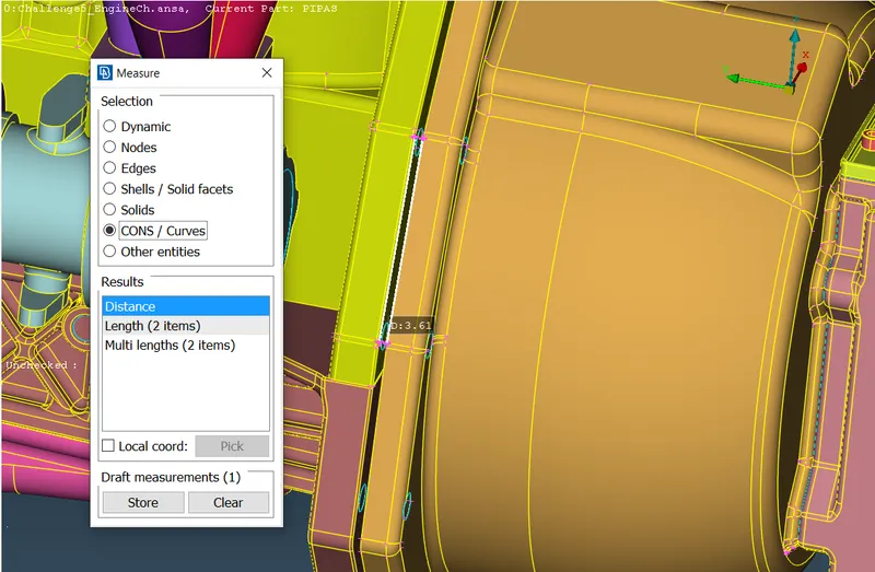
- Compression of not necessary PIDs:
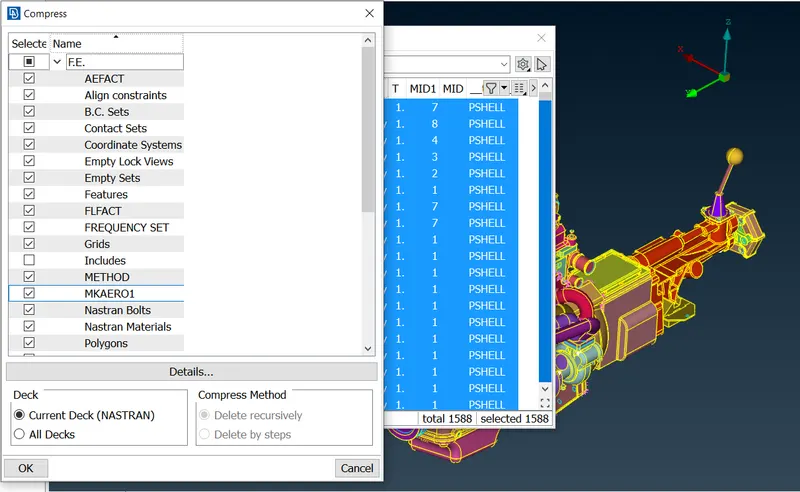
1) The number of PIDs from whole assembly found to be very high i.e. 1588 and most of them are inactive. 2) So the inactive PIDs are compressed. 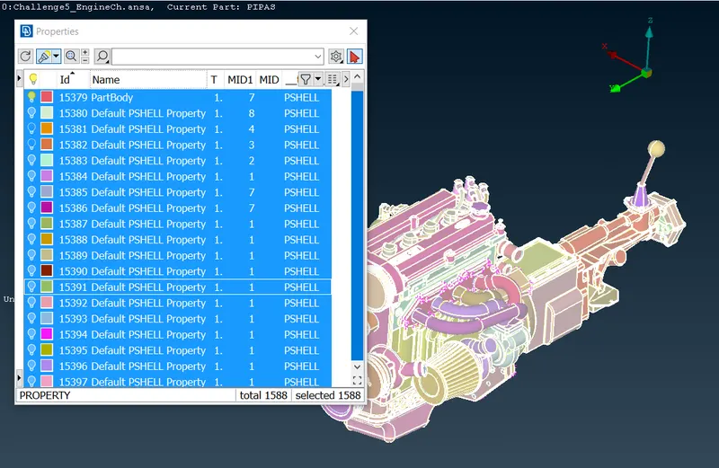
3) The final number of PIDs involved into wholw assembly is reduced to 118. 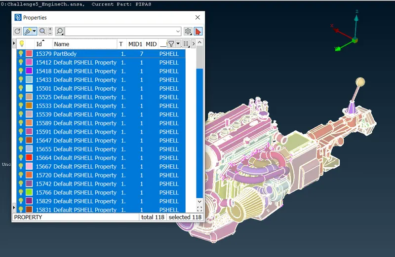
- Surface wrap of the whole assembly:
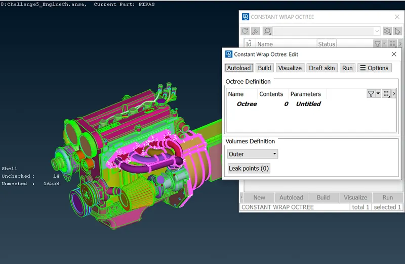
1) To perform a surface wrap go to mesh deck and into the elements long click wrap and select the constant length. 2) Which will open constant wrap octree edit window under which contacts 0 and parameters untitled. Volume defination outer is right with leak points 0. Double click on untitled to open constant wrap octree parameters window. 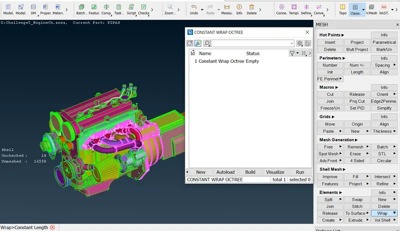
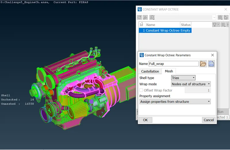
3) Into the wrap parameters window give name as "Full_wrap" and under castellation set target length as 3 mm. 4) Into wrap parameters under mesh check shell type is trias and keep wrap mode and property assignment as default. Click OK. 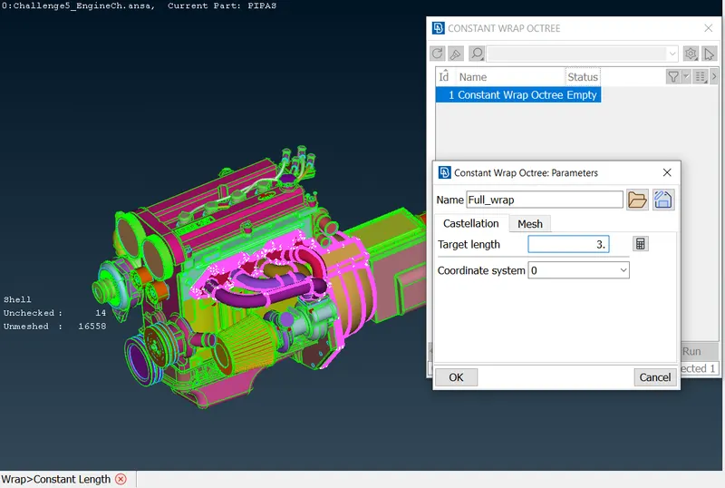
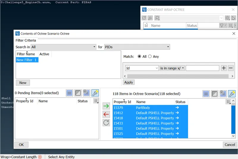
5) Which opens contents of octree scenario where required PIDs are selected inpending items. Here all 118 PIDs are selected in pending items. 6) All selected pending items are transfered to octree scenario. Then click OK. 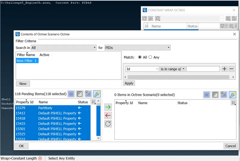
7) Now constant wrap octree showing 118 contents and full_wrap under parameters. Click Run. 8) The constat wrap takes some time to be completed. The view of full wrap showing type and count of shell elements. 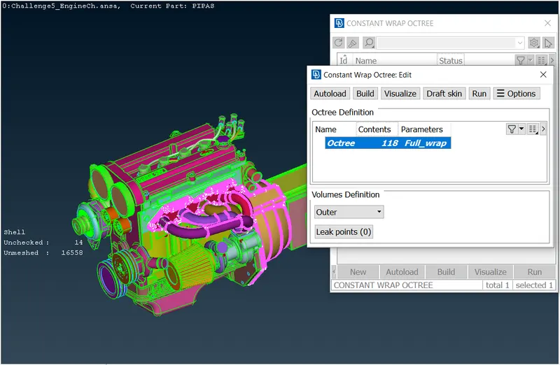
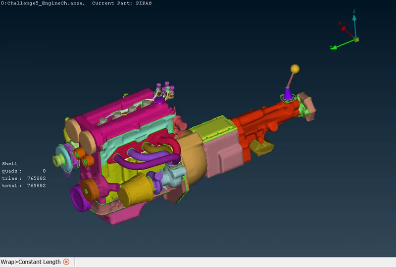
9) Side view of surface wrap showing wrap surfaces. 10) The view of surface wrap showing over gearbox and transmission. 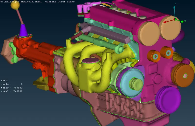
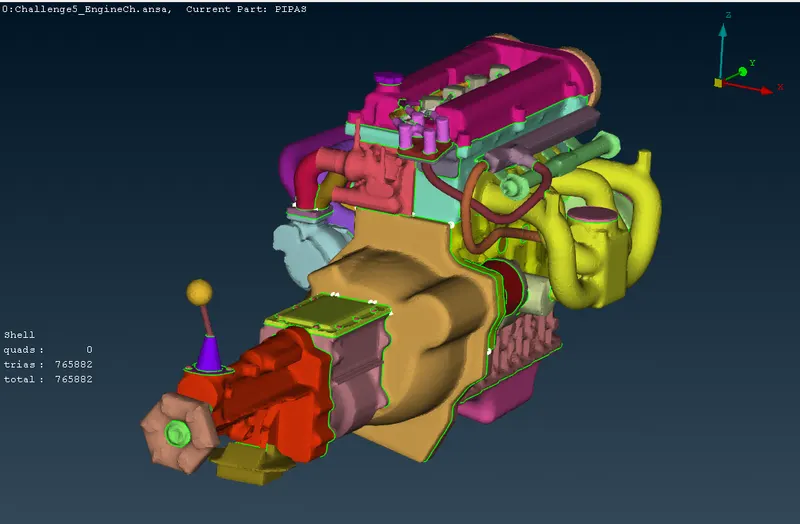
11) View of the surface wrap. 12) Side view of the surface wrap. 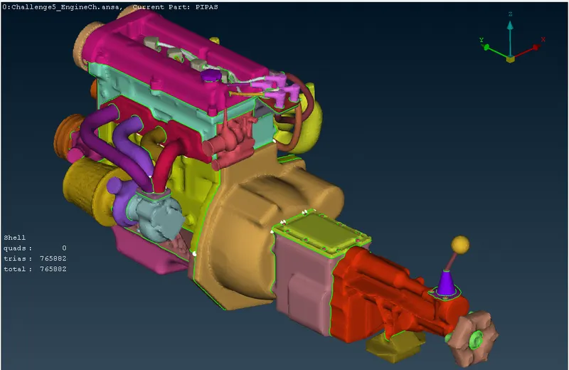
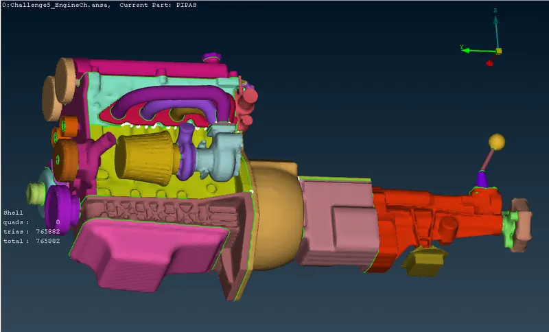
13) End sectional view showing shwing closed internal volume of surface wrap. Background is visible. 14) End sectional view showing shwing closed internal volume of surface wrap. Background is visible. 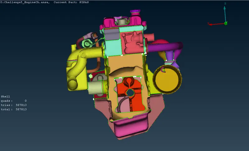
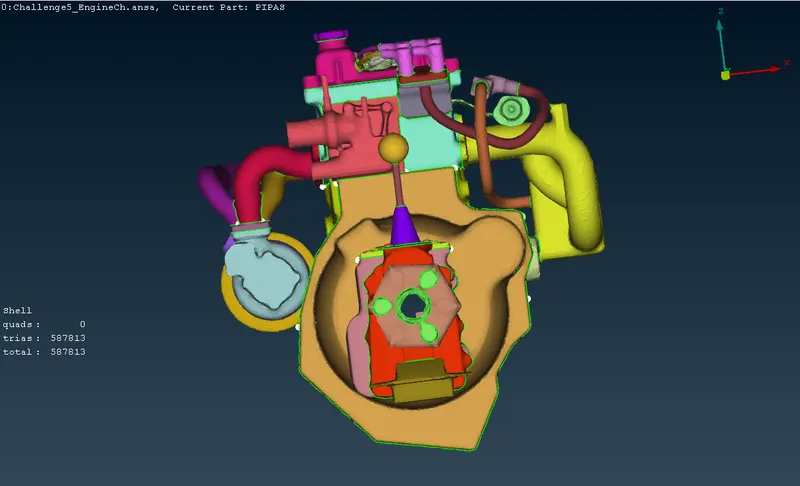
15) Top view of the surface wrap of gearbox and transmission assembly. 16) Top view of surface wrap over engine assembly. 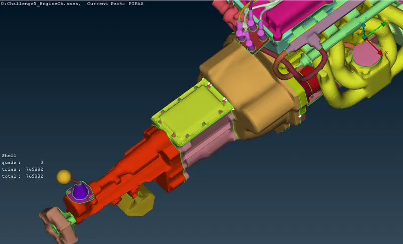
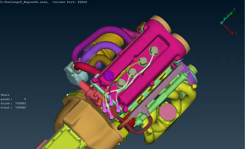
17) The close of surface wrap view around air filter. 18) The close of surface wrap view around pulleys drives. 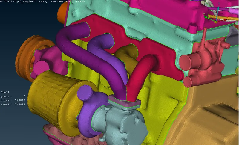
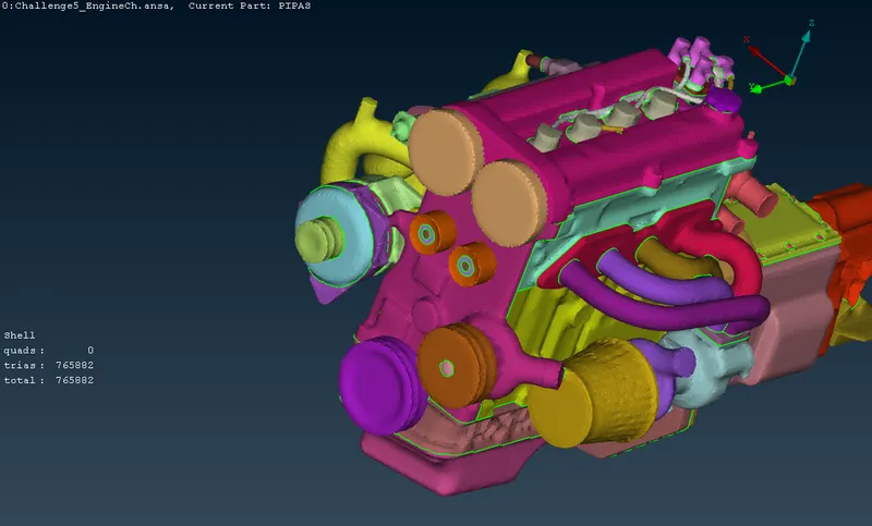
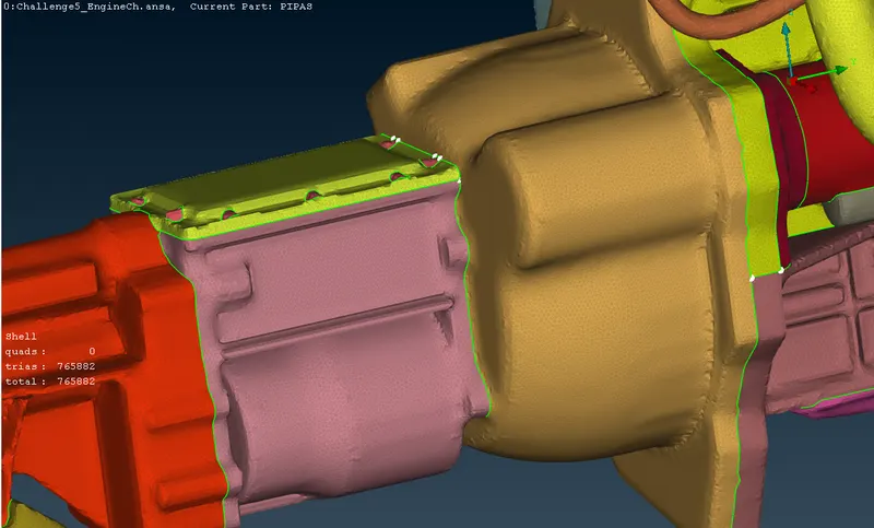
19) The close of surface wrap around exhaust pipes. 20) The close view of surface wrap over gearbox. 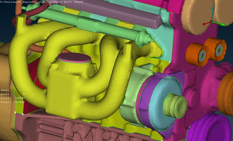
a) As the whole model files are attached here by spliting the file into merged assembly file and the surface wrap file.
Conclusions:
- The surface cleaning necessary for surface wrap has been successfully done here.
- The merging of various assemblies is succesfully done here.
- The whole assembly surface wrap has been successfully done here.