Week 3 Challenge : CFD meshing on Turbocharger
Aim: For the given geometrical model of Turbocharger,
To check for the geometrical errors to make appropriate volumes.
To Create and to assign PIDs as shown in the video lecture.
To Perform surface mesh with the given target lengths as per PIDs.
- Blade stage-1 = 1 mm
- Blade stage-2 = 1 mm
- Impeller = 2 mm
- Shaft rotor = 1 mm
- Turbo casing, inlet and outlet = 5 mm
- Compressor casing, inlet and outlet = 5 mm
- Inlet casing cover = 5 mm
To Perform Volumetric mesh for the required volumes as shown in the videos.
To Write a detailed report on your surface meshing & Volume meshing process.
Given: The geometrical of the Turbocharger.
Steps to check and eliminate the geometrical errors in the existing geometrical model:
- Topological cleanup of the Compressor casing and Turbocharger casing (To eliminate surface glichings).
i) Observed Glichings: Indication of overlapped surfaces ii) Compressor casing isolation of the overlapped surfaces using !Not command and deleted the same using Faces>Delete. 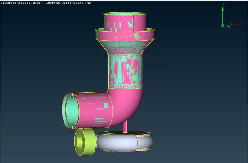
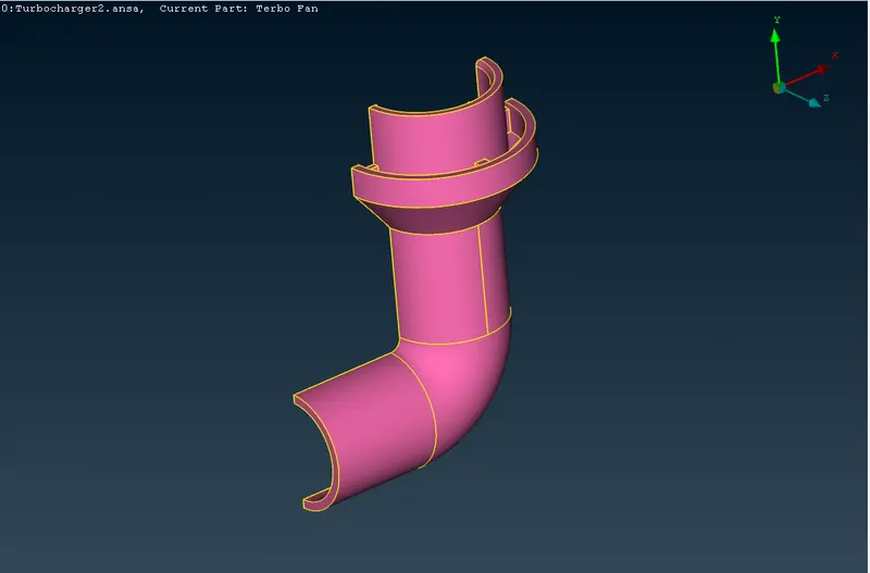
iii) The compressor casing after removal of overlapped surfaces iv) More overlapped surfaces at the contact of shaft rotor and compressor casing 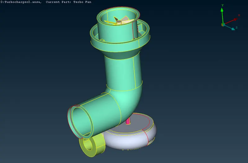
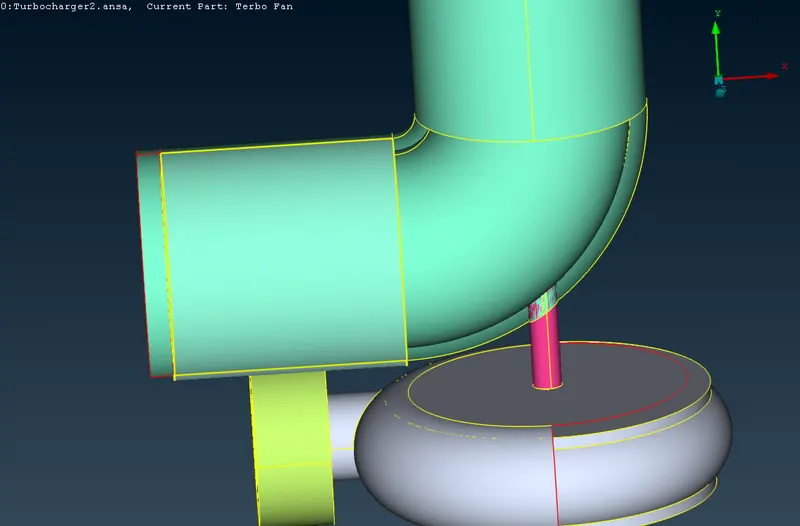
v) Sectional view of compressor casing after removal of overlapped surfaces from (iv) using Faces>Delete command. vi) Overlapped surfaces from the contact of turbocharger casing and shaft rotor 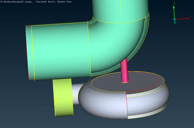
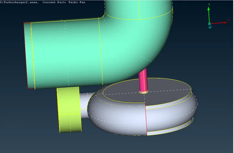
vii) Turbocharger sectional view after removal of overlapped surfaces using Faces>Delete command. viii) Projection of edge on the extended surface from Outlet of compressor casing by using command Cons>Project. 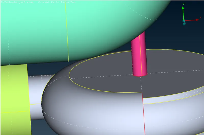
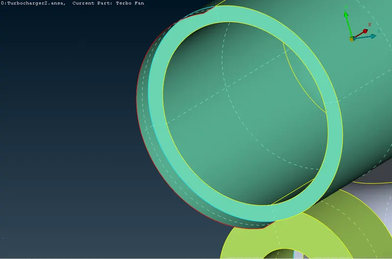
ix) Removal of Extended surface from Outlet of compressor casing by using command Face>Delete - To delete the extended face. x) Single cons appeared due to removal of overlapped surfaces from the contact of shaft rotor with compressor and turbocharger casing. 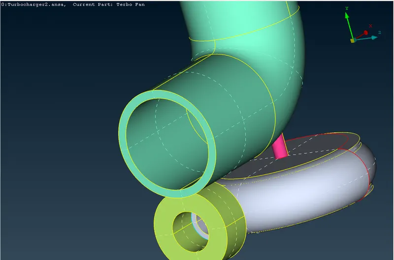
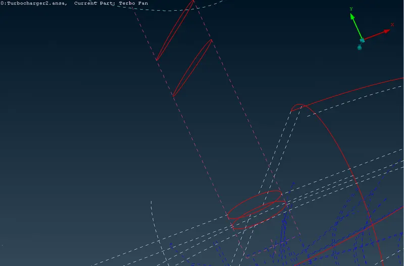
xi) Coverting the single cons from (x) to necessary triple cons by projecting the single cons on the shaft rotor surface using command Cons>Project. xii) 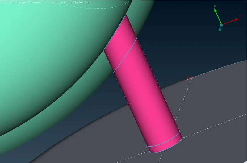
- To eliminate single cons from the Compressor casing. To creat the missing surfaces wherever necessary.
i) Single cons due to surface extensions which must intersected. ii) Eliminated single cons by resolving the surface intersection issue using
Faces>Intersect command.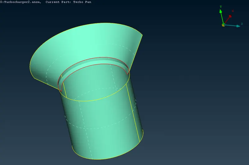
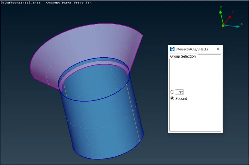
iii) Final view after retaining the required surfaces. iv) Single cons due to missing surface on the compressor casing. 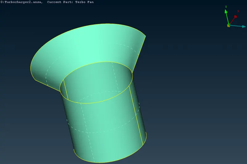
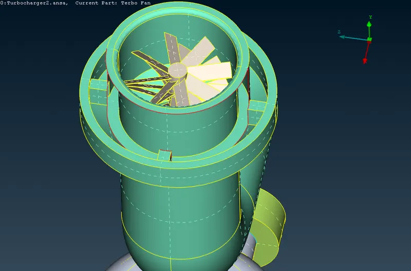
v) Projecting the multiple hot points on the top rim single con using Hot Points>Multi. Project Command. vi) Creating the Missing surface in parts by Faces>New>Fitted and COONS commands. 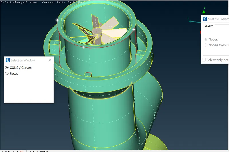
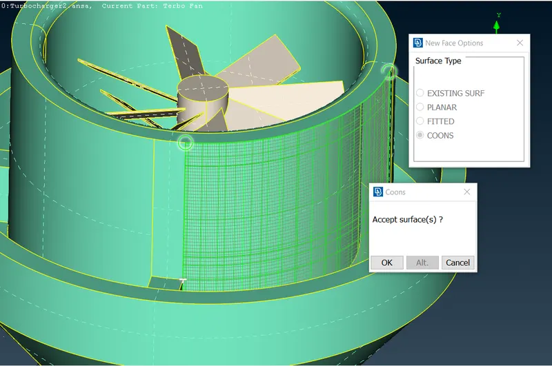
vii) The excess holes in the compressor casing should be filled in order to make the closed volume inside the compressor casing. viii) Triple cons are formed after filling all of the four excess holes in the compressor casing geometry. 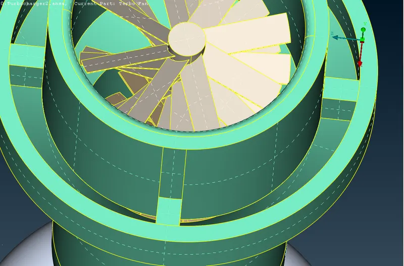
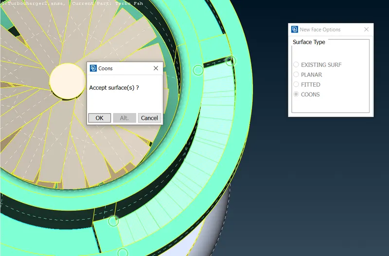
ix) Creat surface at Compressor inlet by Faces>New command which will creat new triple con. x) The newly created surface at compressor inlet and respective triple con. 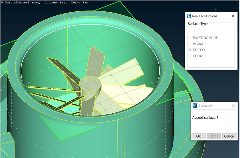
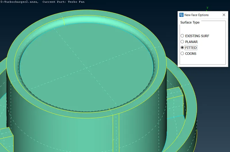
xi) Creat surface at Compressor outlet by Faces>New command which will creat new triple con. xii) The newly created surface at compressor outlet and respective triple con. 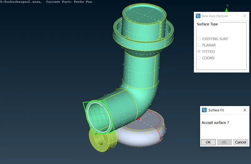
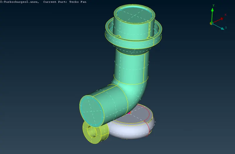
- To creat the missing surfaces from the Turbocharger casing(To eliminate single cons).
i) Missing surfaces from the Turbocharger Casing ii) Multiple hot points are created on the single con on the edge of the casing using Hot points>Parametrical command. 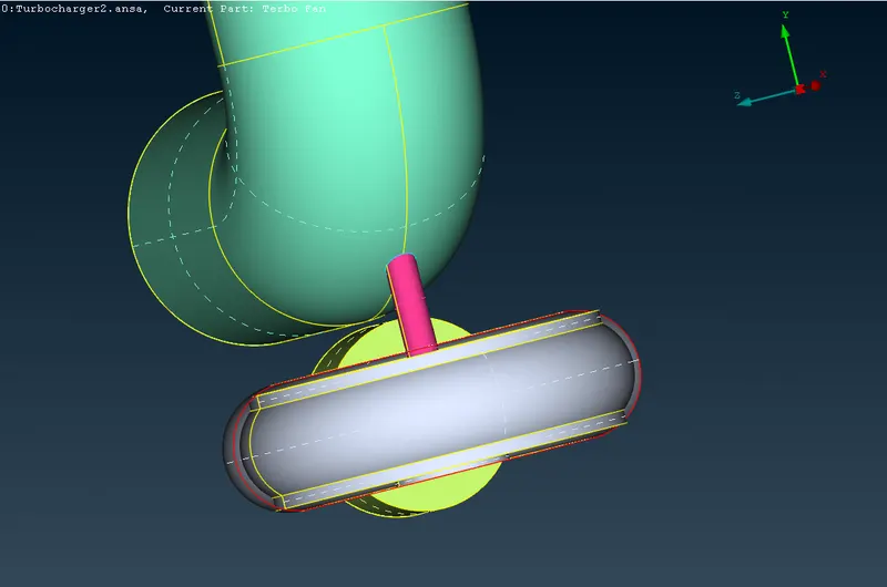
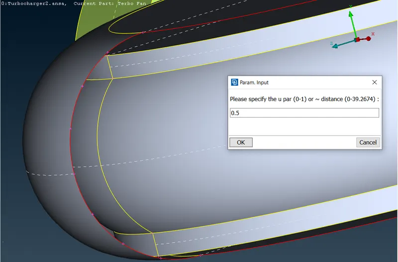
iii) Similarly the multiple hot points are created on other edge using
Hot points>Parametrical command.iv) Missing surface has been created in the parts using Faces>New>COONS command. Part 1 is shown here. 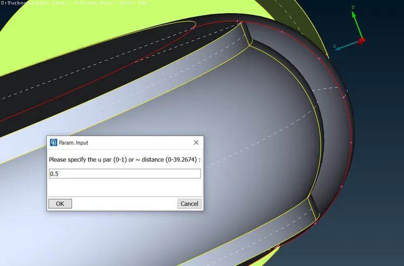
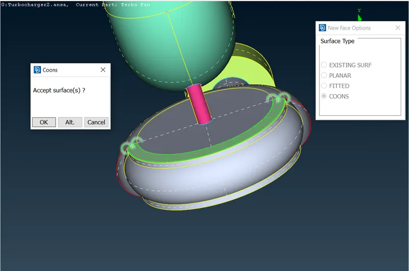
v) Missing surface has been created in the parts using Faces>New>COONS command. Part 2 is shown here. vi) Missing surface has been created in the parts using Faces>New>COONS command. Part 3 is shown here. 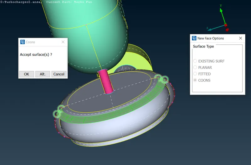
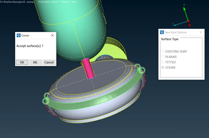
vii) Missing surface has been created in the parts using Faces>New>COONS command. Part 4 is shown here. viii) Missing surface has been created in the parts using Faces>New>COONS command. Part 5 is shown here. 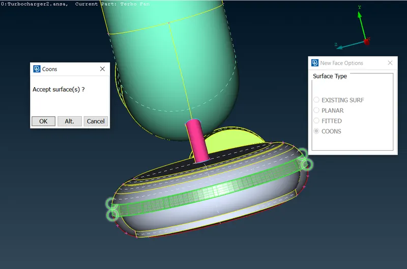
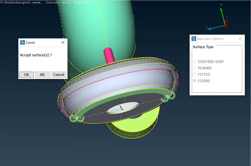
ix) Missing surface has been created in the parts using Faces>New>COONS command. Part 6 is shown here. x) Missing surface has been created in the parts using Faces>New>COONS command. Part 7 is shown here. 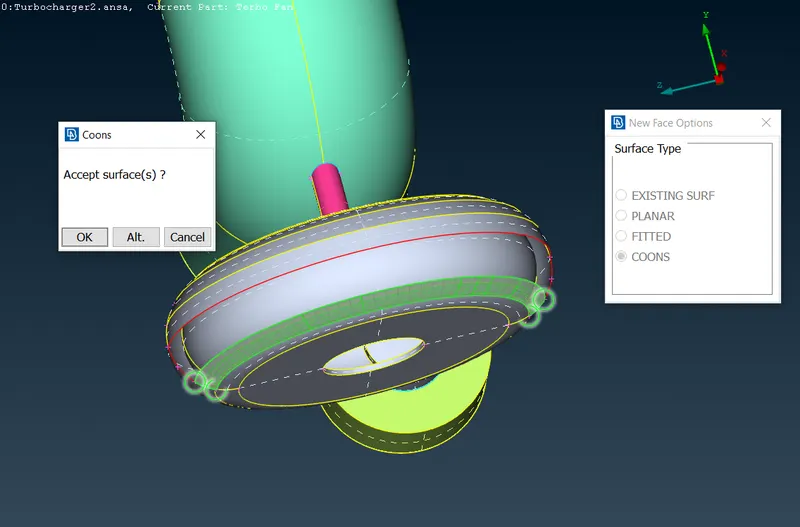
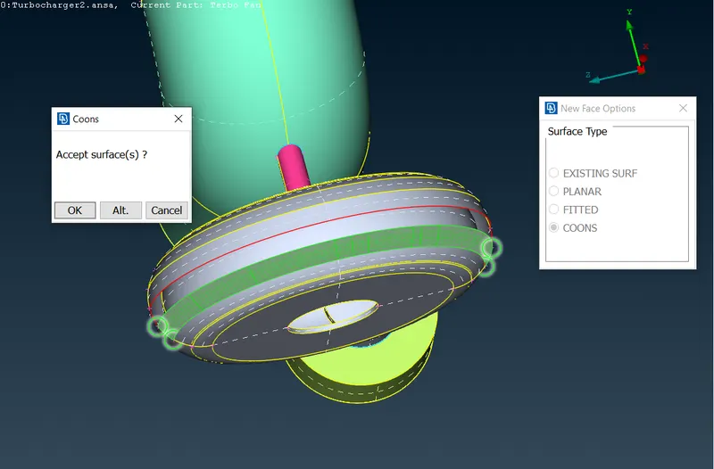
xi) Missing surface has been created in the parts using Faces>New>COONS command. Part 8 is shown here. xii) The Turbocharger casing after the creation of missing surfaces. 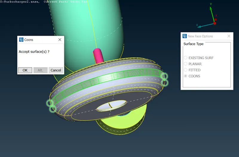
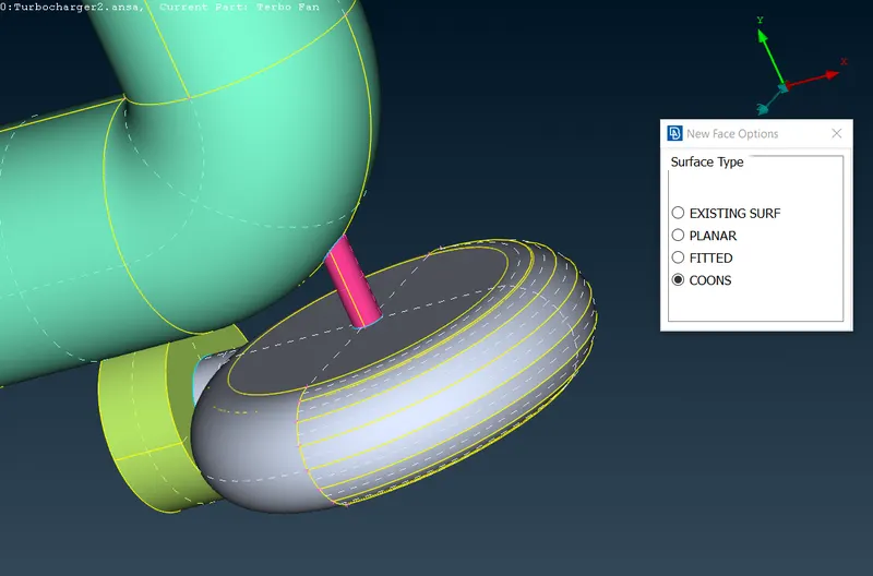
xiii) Creat surface at the inlet of Turbocharger inlet casing by Faces>New command which will creat new triple con. xiv) The newly created surface at inlet of Turbocharger inlet casing and respective triple con. 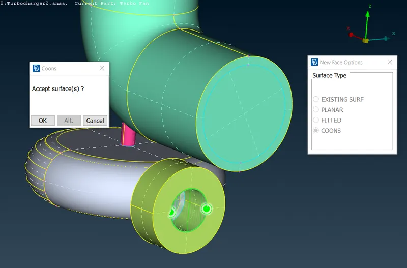
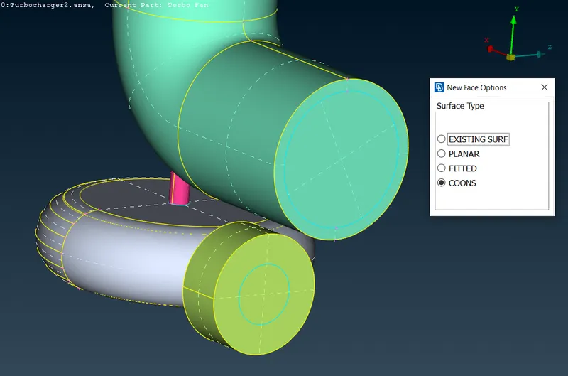
xv) Creat surface at Turbocharger outlet by Faces>New command which will creat new triple con. xvi) The newly created surface at Turbocharger outlet and respective triple con. 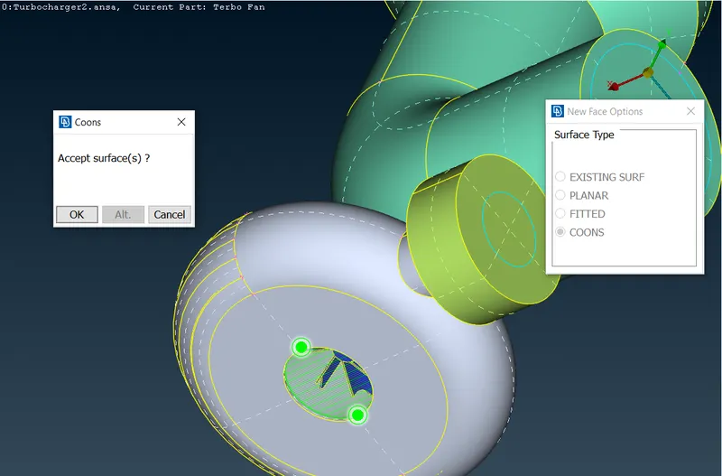
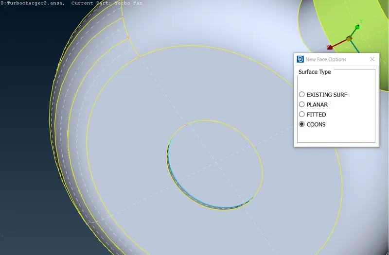
- To creat the single volume of the shaft rotor with compressor blades and turbocharger impeller.
i) Isolation of Shaft Rotor assembly and performing Faces>Topo command shows the presence of excess triple cons and overlapped surface. ii) Removal of extra surfaces from the Blades Stage_1 assembly to eliminate triple cons. 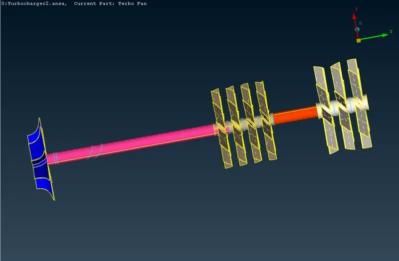
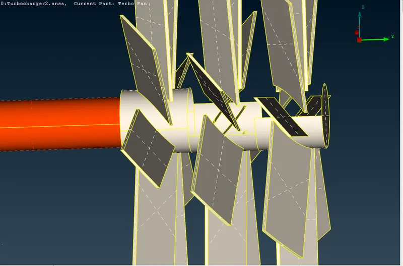
iii) As both end surfaces are distinct.Projecting the shaft rotor end surface on the Blades stage_1 surface in contact with shaft rotor using Cons>Project command. The respective triple con is formed. iv) Removal of extra surfaces and triple con formed due to action (iii) using Faces>Delete command. 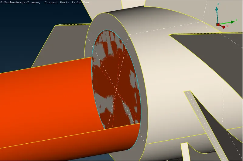
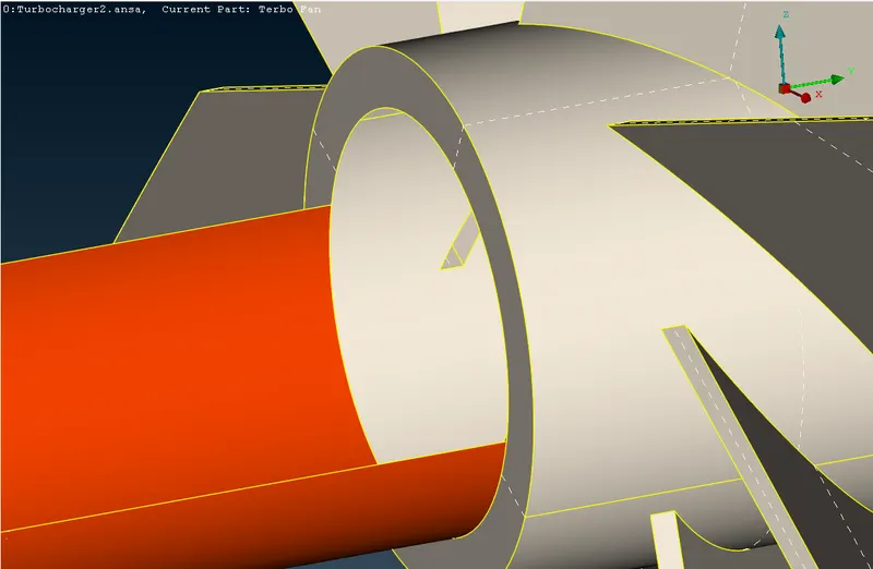
v) Triple cons at Blades stage_2 due to extra surfaces which have been
removed by Faces>Delete command. Also overlapped surfaces have been observed indicated by glichings.vi) To remove overlapped surfaces the edge of the blades stage_2 has been projected over a shaft rotor surfaces. Which forms another triple con, same has been eliminated by deleting extra surfaces using Faces>Delete command. 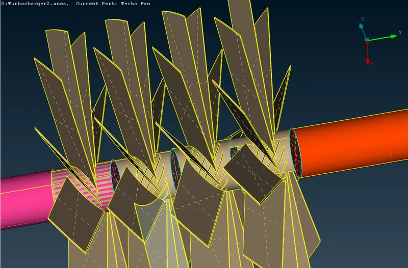
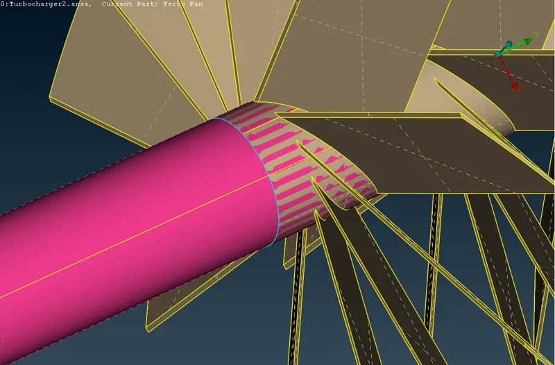
v) To remove the extra surfaces which are ovelapping and responsible for extra triple con formation the command Faces>Delete has been used. vi) Presence of Overlapped surfaces at the contact surface of the Impeller and Shaft Rotor. 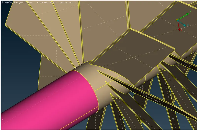
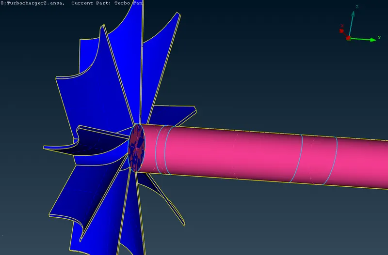
vii) Projection of shaft rotor surface on the impeller surface as impeller blade surfaces also connected to base surface. viii) Removal of impeller central face. This will make common inner volume as we deleted all the internal faces from shaft rotor and blades stage_1 and stage_2. 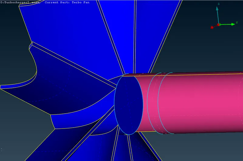
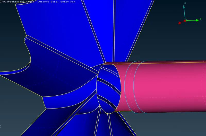
ix) Check 1: For confirmation of common inner volume. View from Impeller end after hiding the impeller and blades stage_1 end surfaces. The assembly is hollow as background is visible. x) Check 2: For confirmation of common inner volume. View from Blades stage_1 end after hiding the impeller and blades stage_1 end surfaces. The assembly is hollow as background is visible. 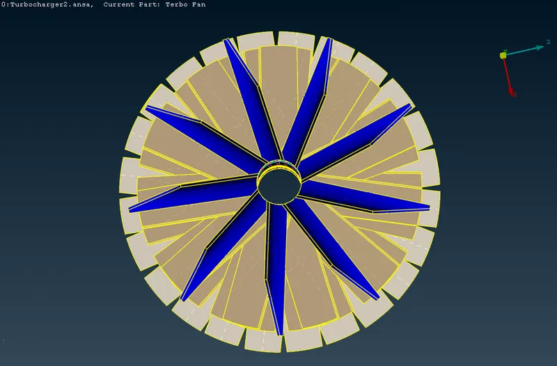
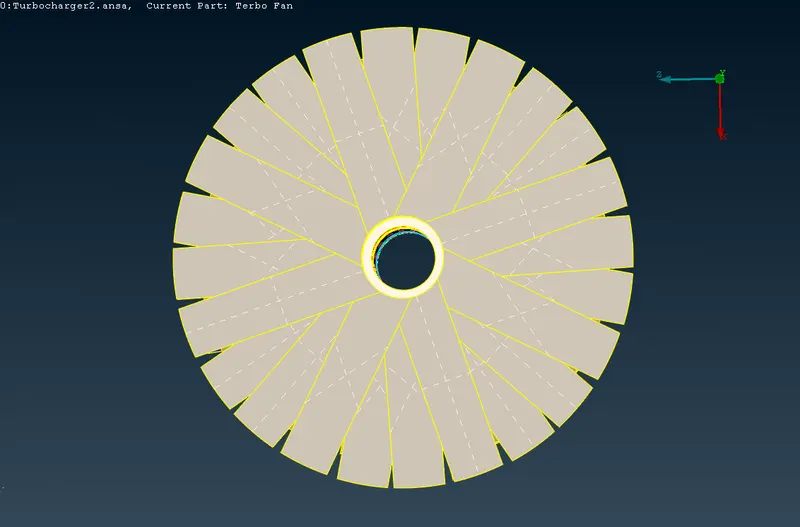
- Geometry check for single cons and triple cons.
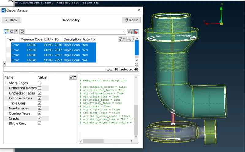
i) Wire Mesh View by turning off the cross hatches and double cons. Only necessary triple cons are visible. Thus model has no errors. ii) Checks>Geometry : Check for single cons and triple cons. Results show necessary triple cons only. Thus geometrical model is error free. 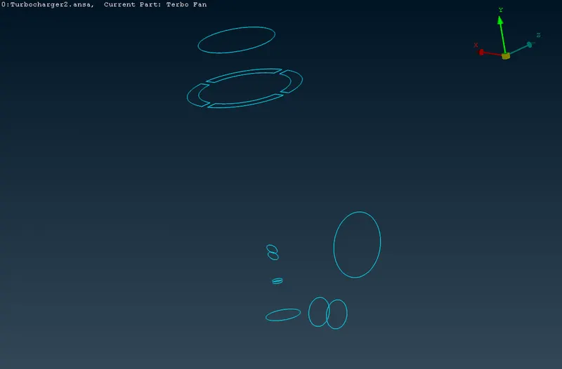
- New PID assignments
i) Non active PIDs from the List are compressed. ii) Cration of new PIDs 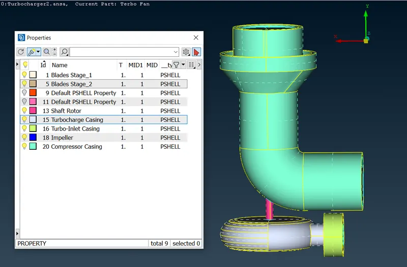
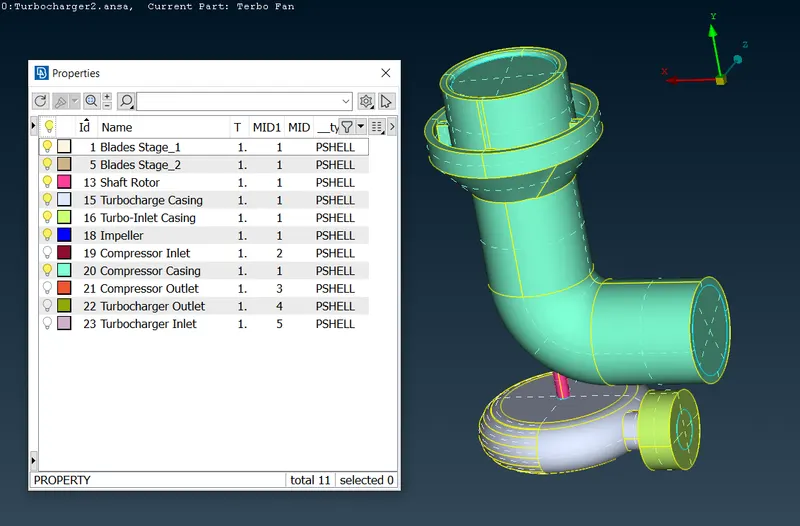
iii) PID assignment for Compressor Inlet iv) PID assignment for Compressor Outlet 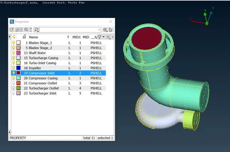
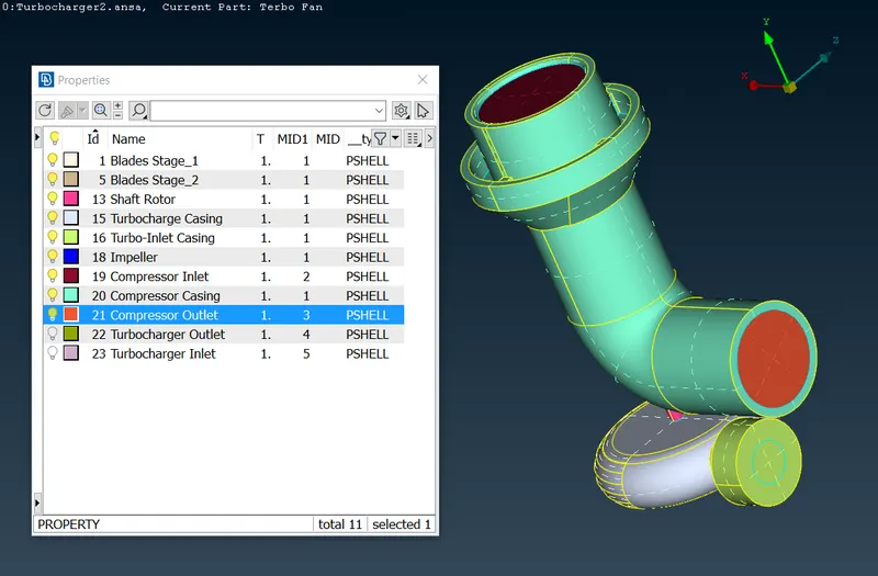
v) PID assignment for Turbocharger Inlet vi) PID assignment for Turbocharger Outlet 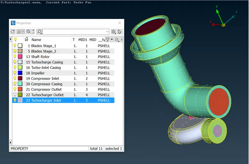
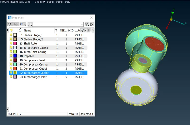
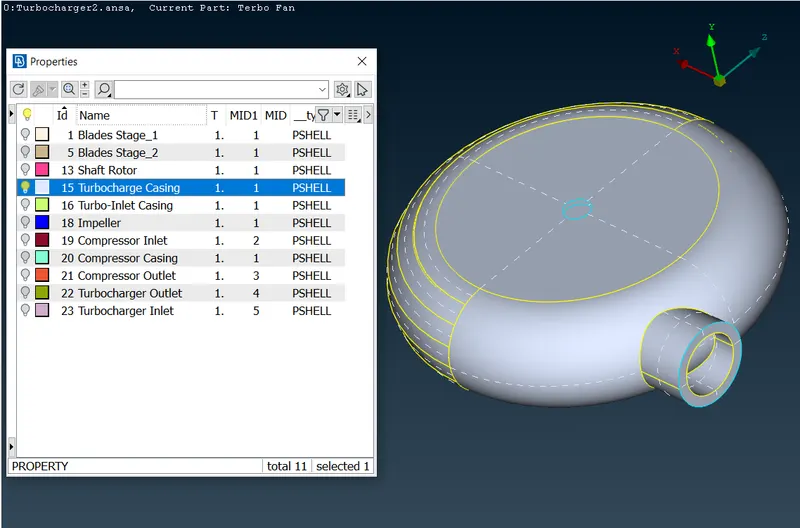
vii) PID assignment for Compressor Casing viii) PID assignment for Turbocharger Casing 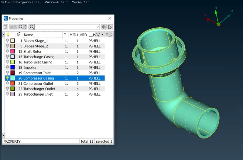
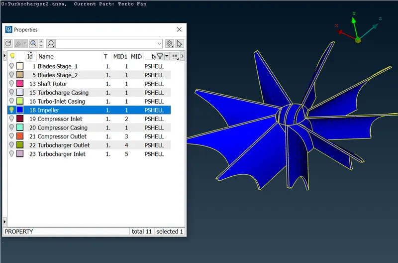
ix) PID assignment for Shaft Rotor x) PID assignment for Impeller 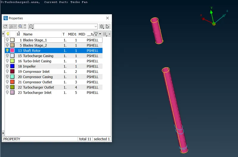
xi) PID assigment for Blades Stage_1 x) PID assigment for Blades Stage_2 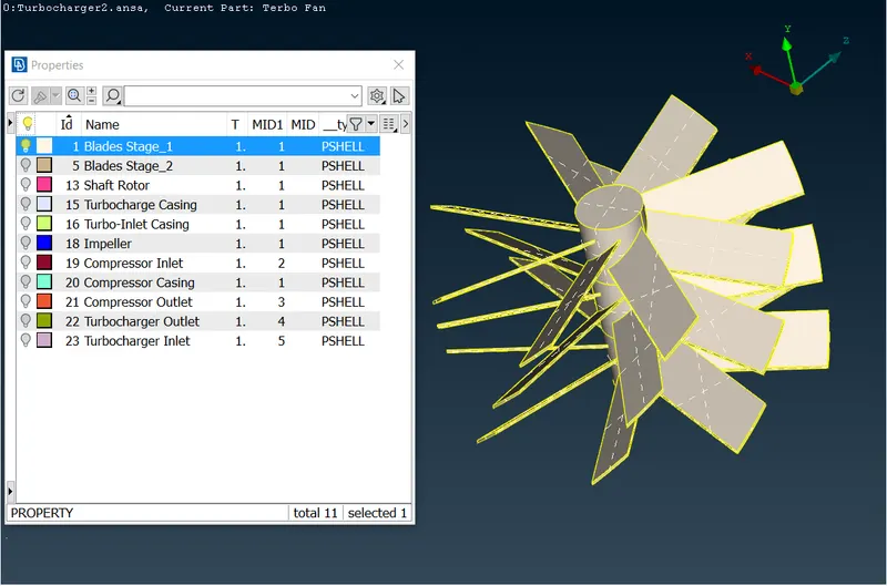
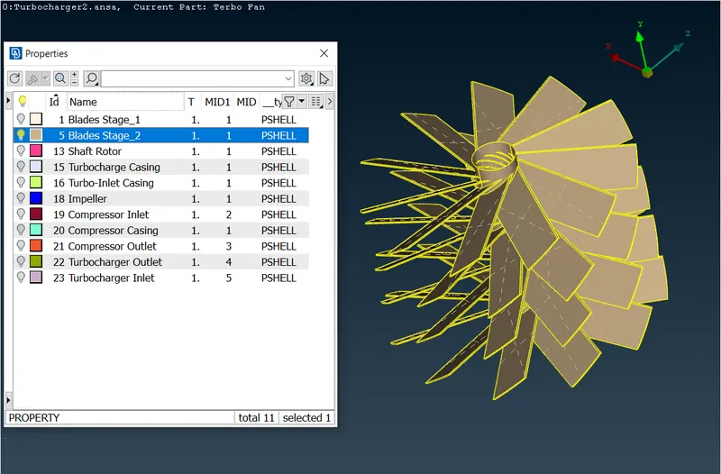
xi) PID assigment for Turbo Inlet Casing xii) Confirmation of all PID assignments. No part is remained for assignment. 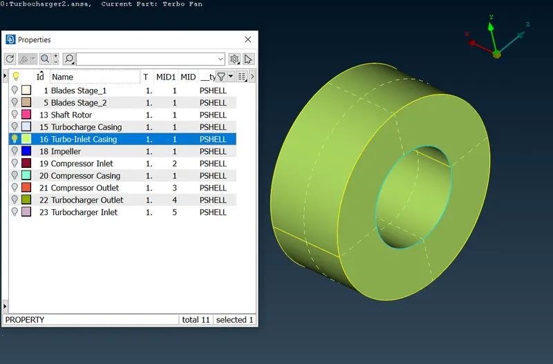
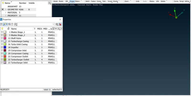
Steps to perform the surface meshing with given target lengths for different PIDs:
- Surface Meshing of the Compressor assembly with 5 mm target length.
(i.e. Compressor casing,Compressor Inlet,Compressor Outlet)
1) Quality criteria for Compressor assembly. 2) Mesh Parameters for Compressor assembly 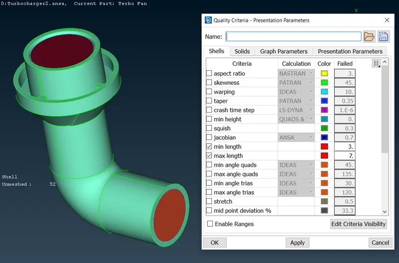
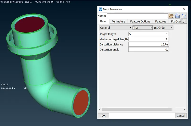
3) Perimeters setting for Compressor assembly under
Perimeters>Length>Perimeter4) Macros setting for Compressor assembly under
Perimeters>Length>Macros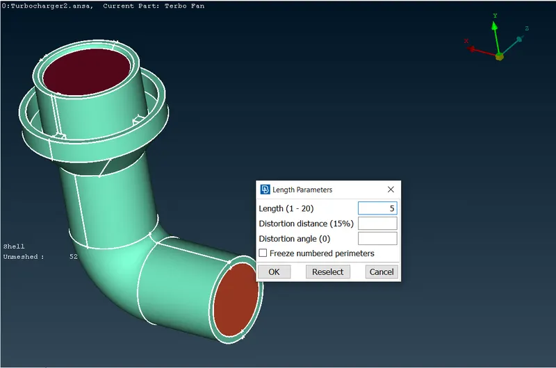
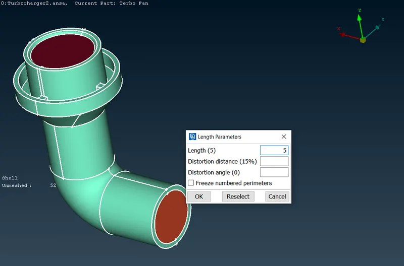
5) Surface Mesh generation for whole compressor assembly with Mesh Generation>Spot Mesh>visible command 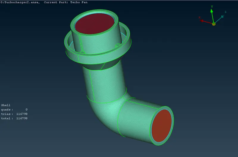
- Surface Meshing of the Turbocharger assembly with 5 mm target length.
(i.e. Turbocharger Casing,Turbo Inlet Casing,Turbocharger Inlet,Turbocharger Outlet)
1) Quality criteria for Turbocharger assembly. 2) Mesh Parameters for Turbocharger assembly. 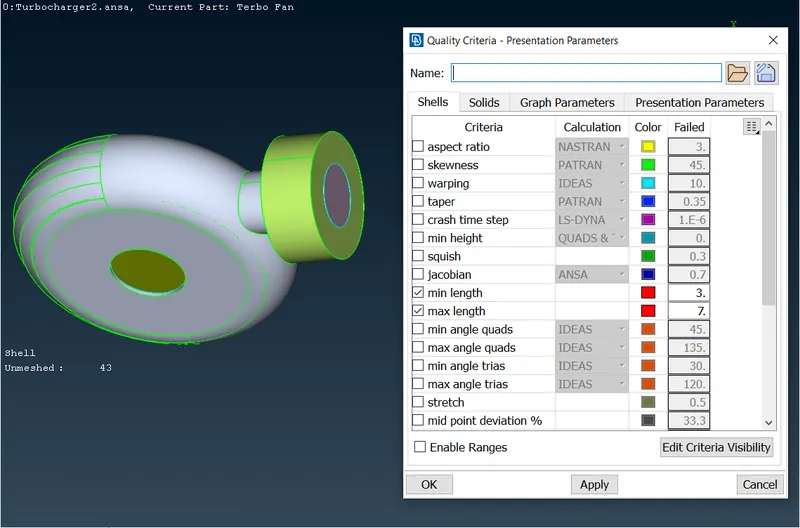
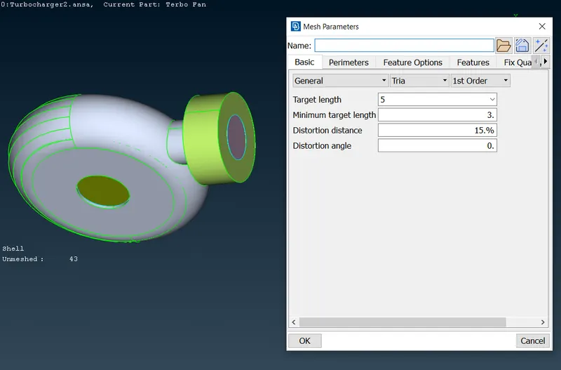
3) Perimeters setting for Turbocharger assembly under
Perimeters>Length>Perimeter4) Macros setting for Compressor assembly under
Perimeters>Length>Macros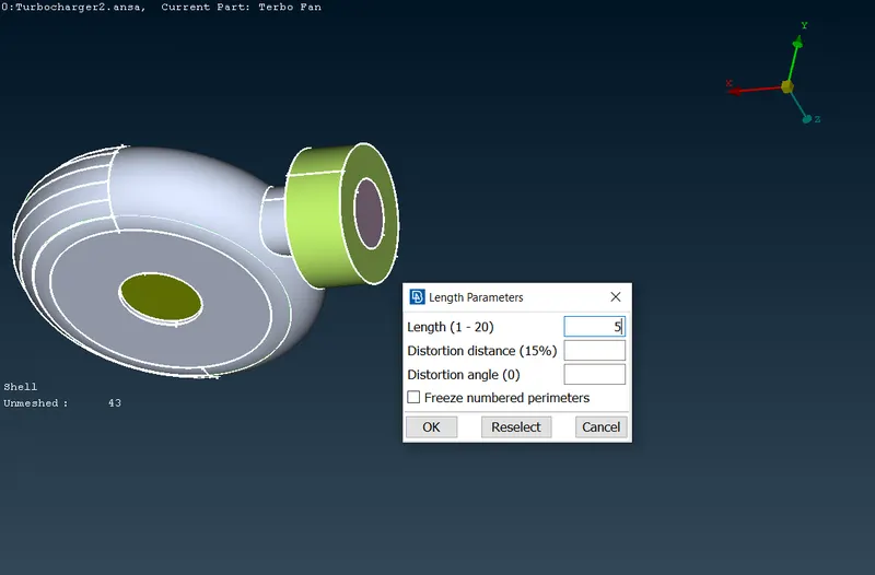
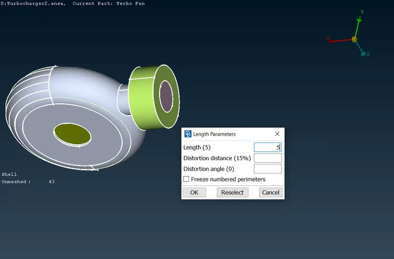
5) Surface Mesh generation for whole Turbocharger assembly with Mesh Generation>Spot Mesh>visible command 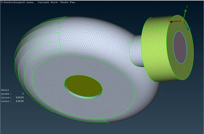
- Surface Meshing of the Blades Stage_1 with 1 mm target length.
1) Quality criteria for Blades Stage_1 2) Mesh Parameters for Blades Stage_1. 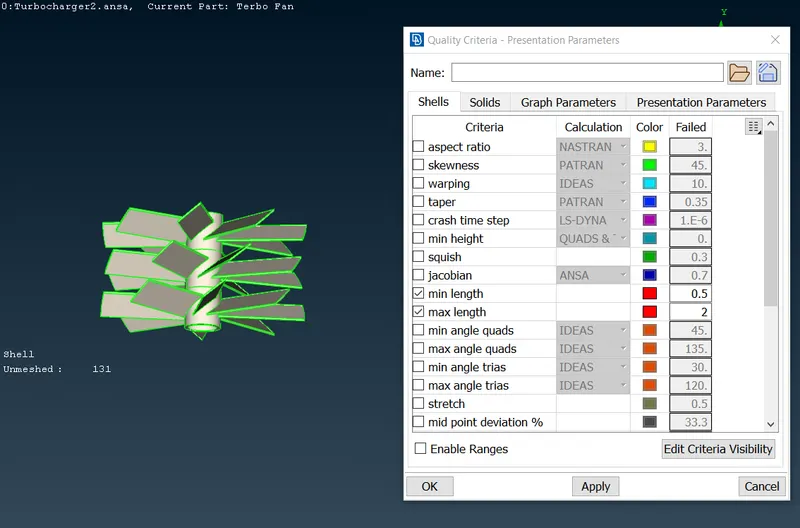
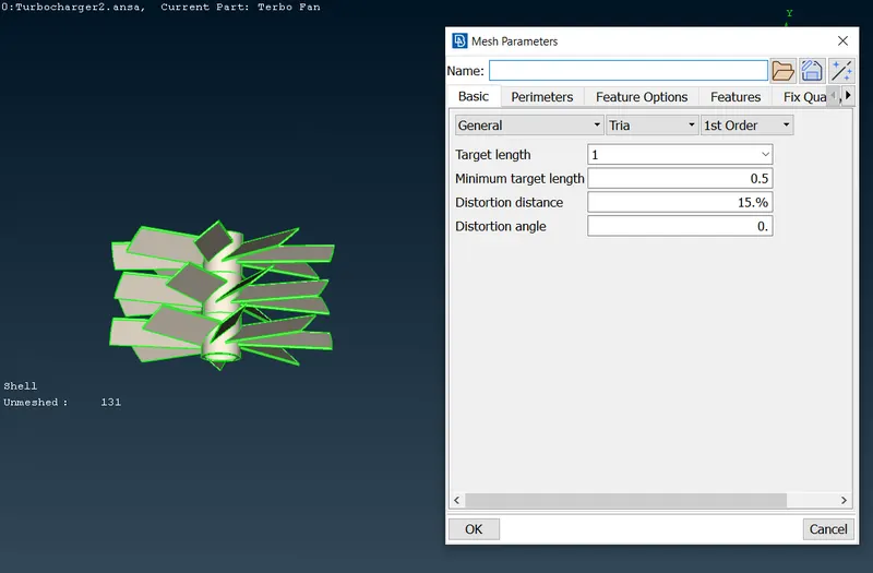
3) Perimeters setting for Blades Stage_1 under
Perimeters>Length>Perimeter4) Macros setting for Blades Stage_1 under
Perimeters>Length>Macros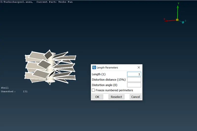
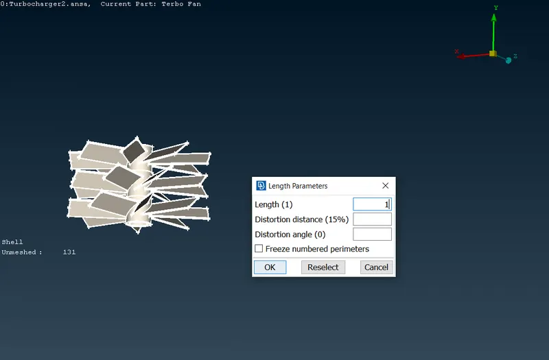
5) Surface Mesh generation for Baldes Stage_1 with Mesh Generation>Spot Mesh>visible command 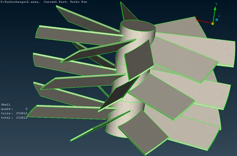
- Surface Meshing of the Blades stage_2 with 1 mm target length.
1) Quality criteria for Blades Stage_2 2) Mesh Parameters for Blades Stage_2. 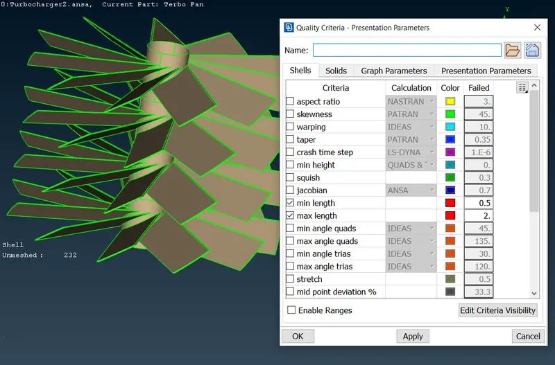
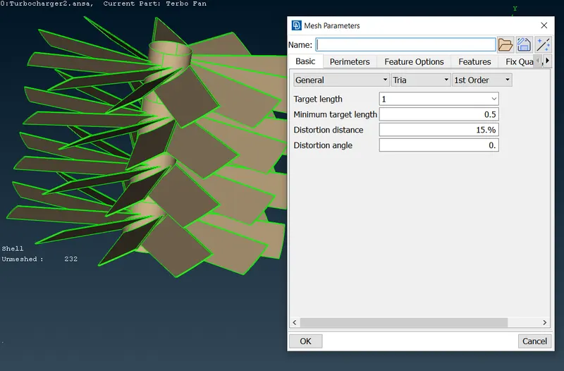
3) Perimeters setting for Blades Stage_2 under
Perimeters>Length>Perimeter4) Macros setting for Blades Stage_2 under
Perimeters>Length>Macros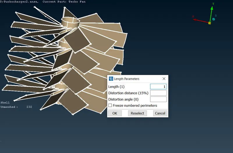
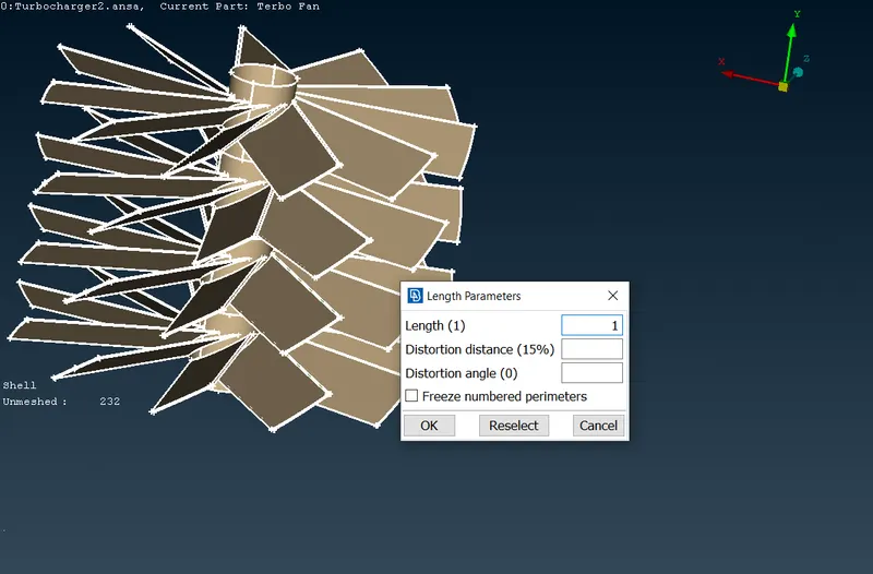
5) Surface Mesh generation for Baldes Stage_2 with Mesh Generation>Spot Mesh>visible command 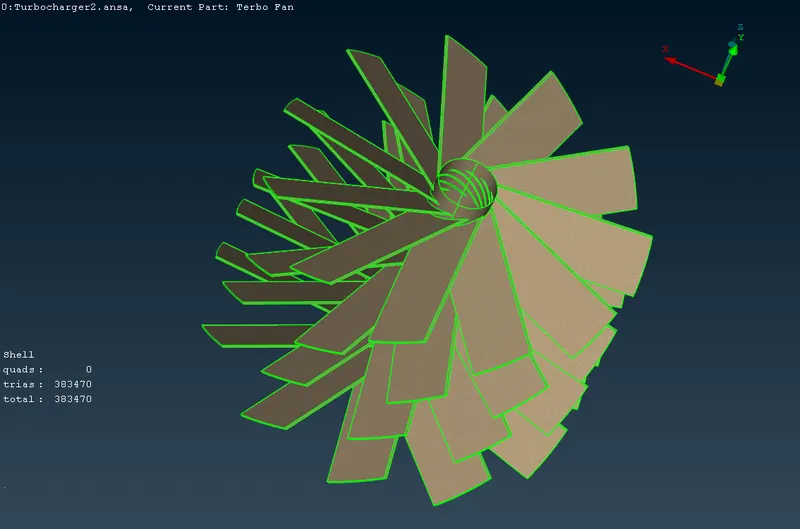
- Surface Meshing of the Shaft Rotor with 1 mm target length.
1) Quality criteria for Shaft Rotor 2) Mesh Parameters for Shaft Rotor 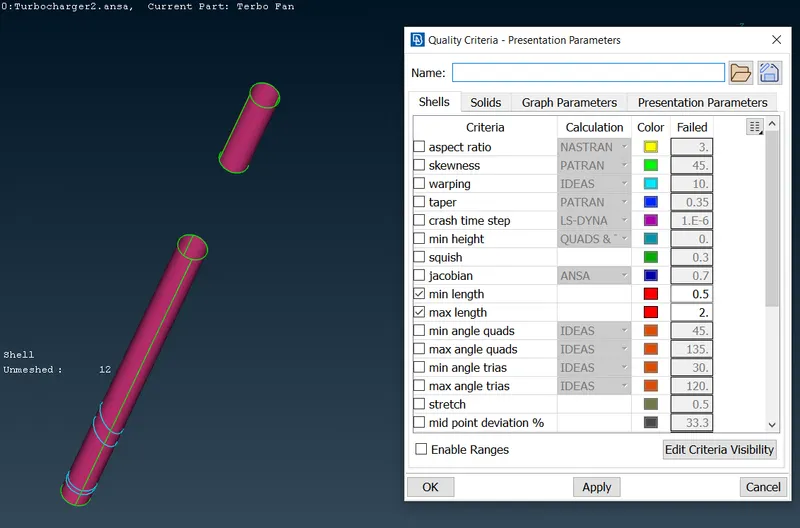
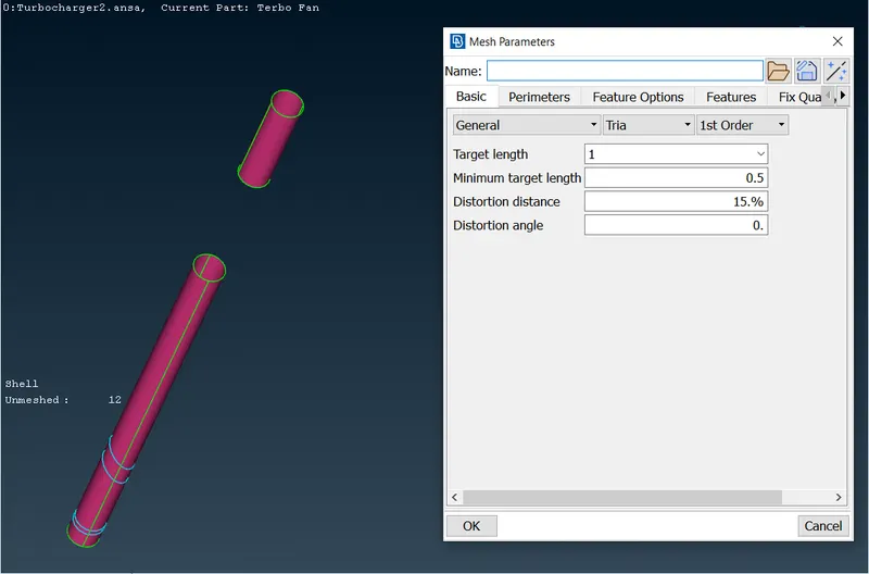
3) Perimeters setting for Shaft Rotor under
Perimeters>Length>Perimeter4) Macros setting for Shaft Rotor under
Perimeters>Length>Macros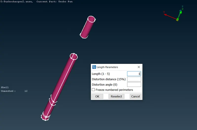
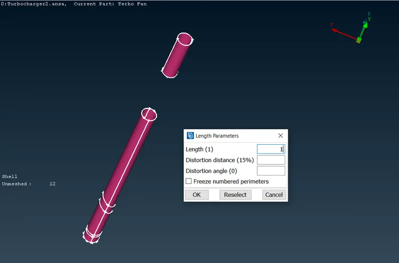
5) Surface Mesh generation for Shaft Rotor with Mesh Generation>Spot Mesh>visible command 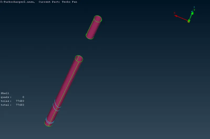
- Surface Meshing of the Impeller with 2 mm target length.
1) Quality criteria for Impeller 2) Mesh Parameters for Impeller 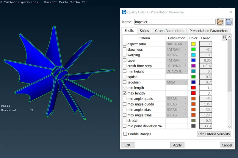
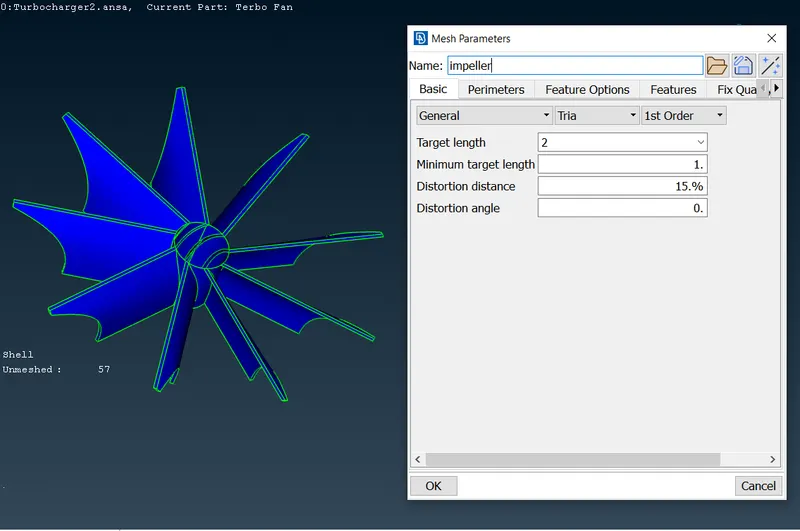
3) Perimeters setting for Impeller under
Perimeters>Length>Perimeter4) Macros setting for Impeller under
Perimeters>Length>Macros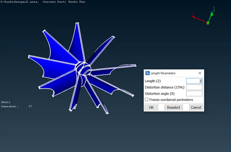
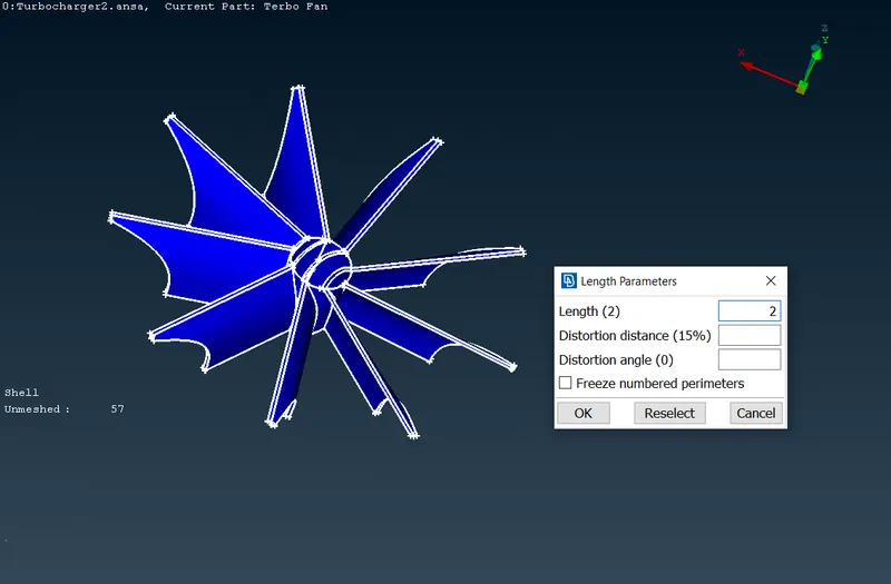
5) Surface Mesh generation for Impeller with Mesh Generation>Spot Mesh>visible command 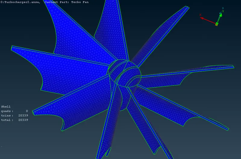
- Locations wheresurface mesh auto delete due to inconsisting target lengths (Total 8 surfaces)
1) Mesh auto deleted at 4 surfaces of Compressor Casing which are in contact with Shaft Rotor. 2 inner and 2 outer surfaces. 2) Mesh auto deleted at 2 surfaces of Turbocharger Casing which are in contact with Shaft Rotor. 1 inner and 1 outer surfaces. Outer surface is shown here. 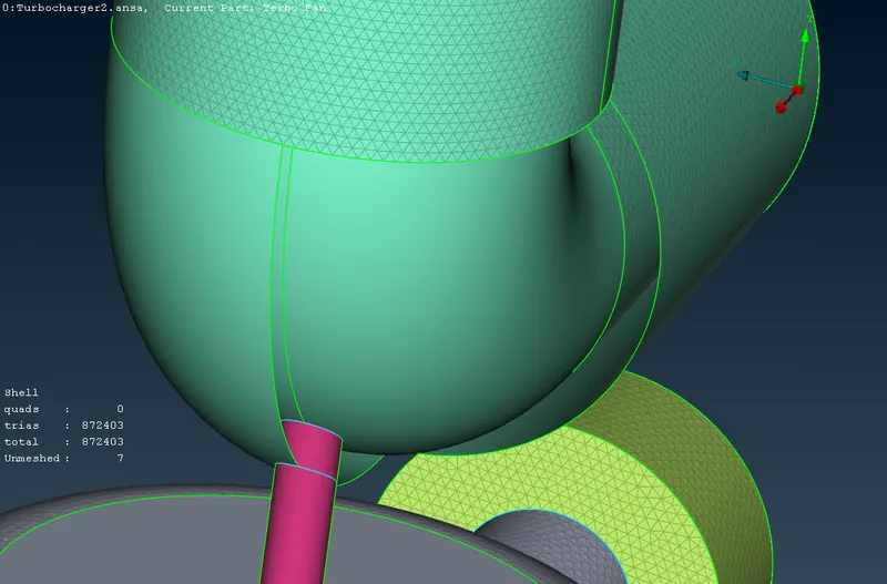
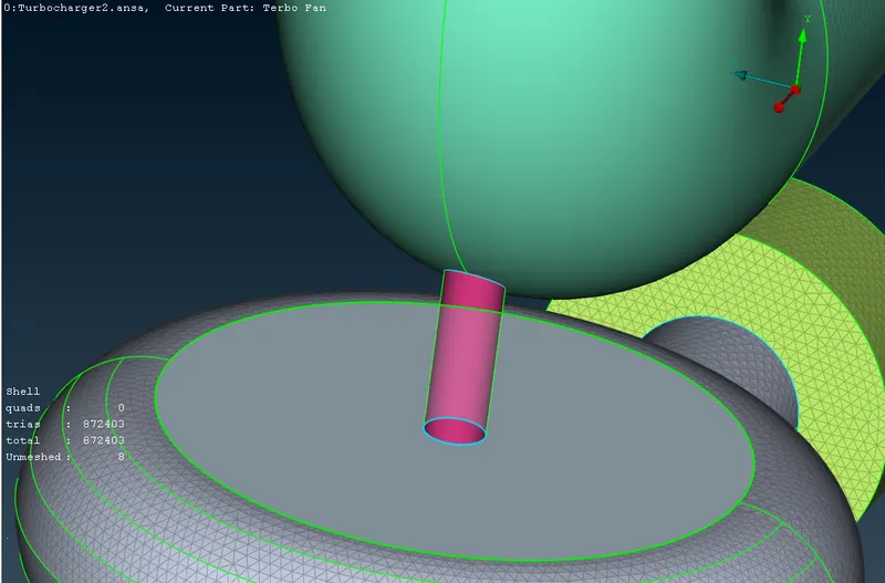
3) Mesh auto deleted at 2 surfaces of Turbocharger Casing which are in contact with Shaft Rotor. 1 inner and 1 outer surfaces. Inner surface is shown here. 4) Mesh auto deleted at 2 surfaces of Shaft Rotor which are in contact with Impeller. Both surfaces are shown here. 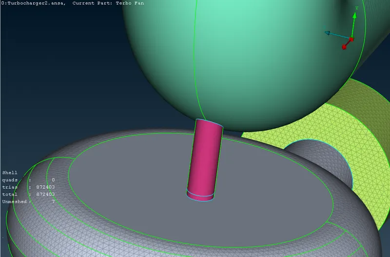
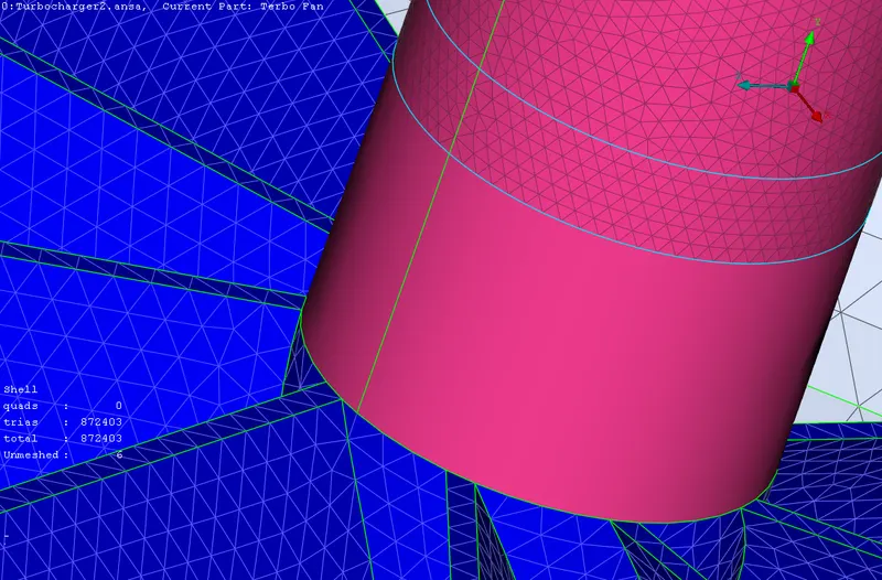
- Surface Meshing of the Shaft Rotor surface connected with Impeller.
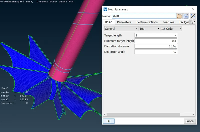
1) Quality Criteria for Shaft Rotor surface connected with Impeller 2) Mesh Parameters for Shaft Rotor surface connected with Impeller 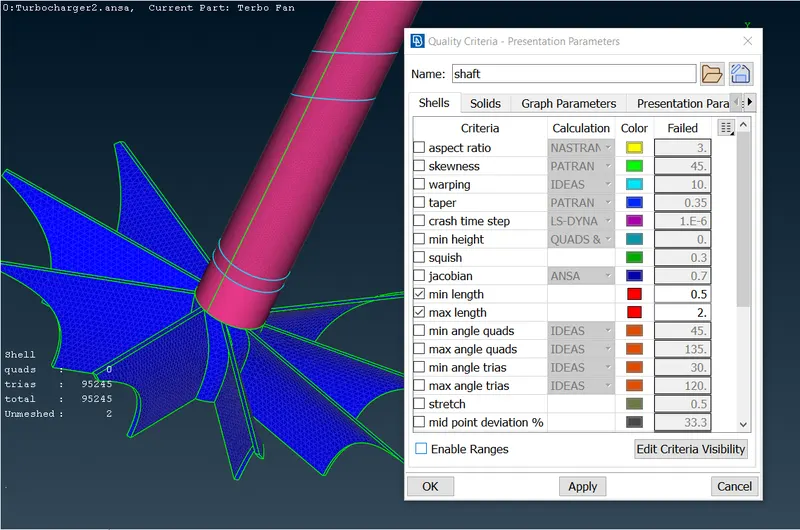
3) Perimeters setting for Shaft Rotor surface connected with Impeller under
Perimeters>Length>Perimeter4) Macros setting for Shaft Rotor surface connected with Impeller under
Perimeters>Length>Macros has been left blank as macro length is varying between 1 to 2 mm.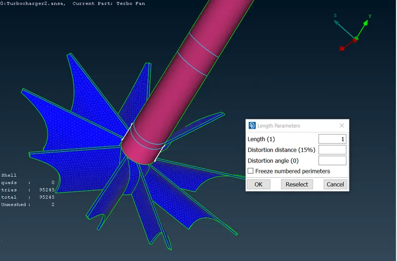
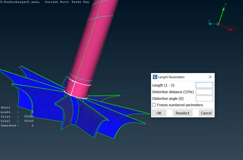
5) Surface Mesh generation for Shaft Rotor surface connected with Impeller with Mesh Generation>Spot Mesh>select command. The required surfaces have been selected as follows. 6) Generated Surface Mesh have been observed as follows. 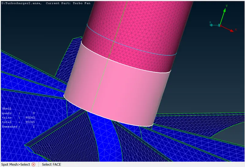
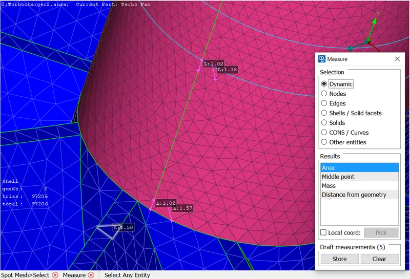
- Surface Meshing of the Turbocharger Casing surfaces connected with Shaft Rotor.
1) Quality Criteria for Turbocharger Casing surfaces connected with Shaft Rotor 2) Mesh Parameters for Turbocharger Casing surfaces connected with Shaft Rotor 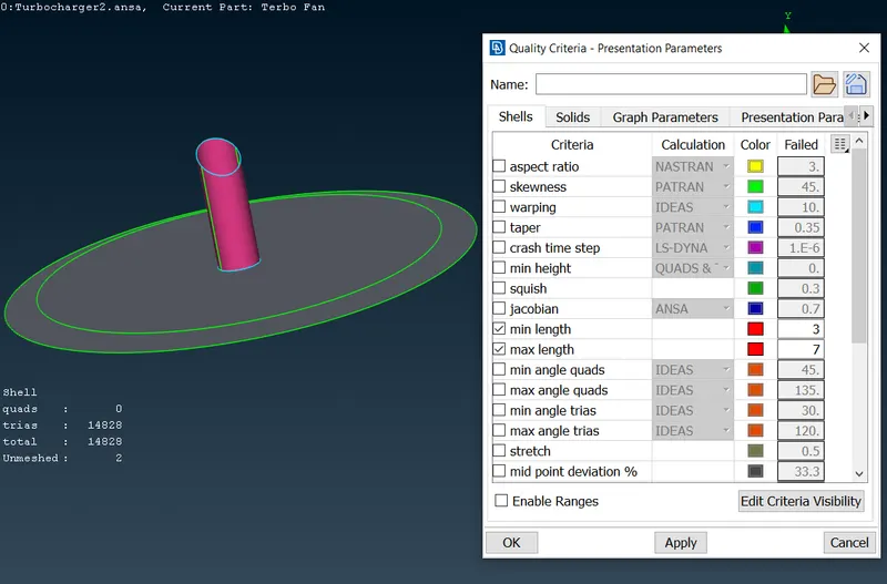
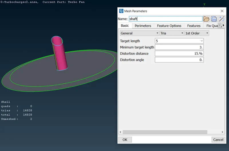
3) Perimeters setting for Turbocharger Casing surfaces connected with Shaft Rotor under Perimeters>Length>Perimeter 4) Macros setting for Turbocharger Casing surfaces connected with Shaft Rotor under Perimeters>Length>Macros has been left blank as macro length is varying between 1 to 5 mm. 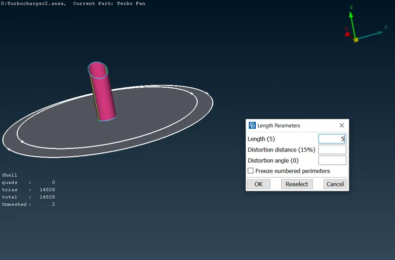
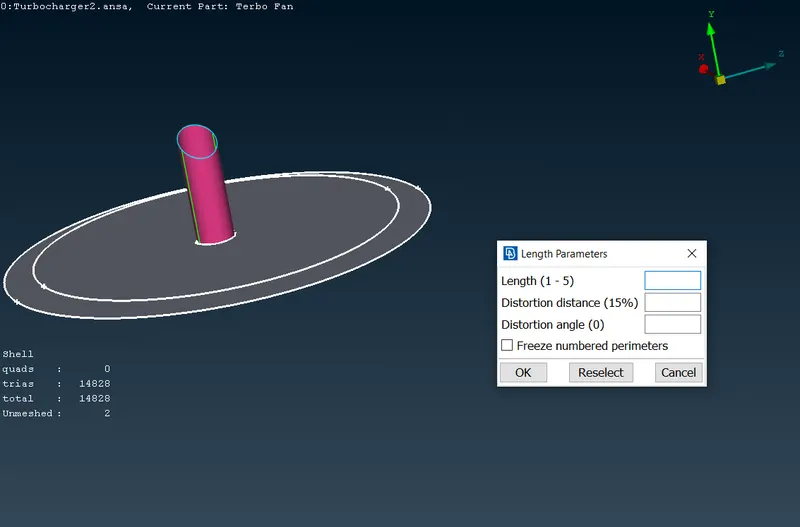
5) Surface Mesh generation for Turbocharger Casing surfaces connected with Shaft Rotor with Mesh Generation>Spot Mesh>select command. 6) Generated Surface Mesh have been observed as follows. 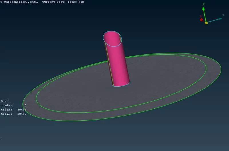
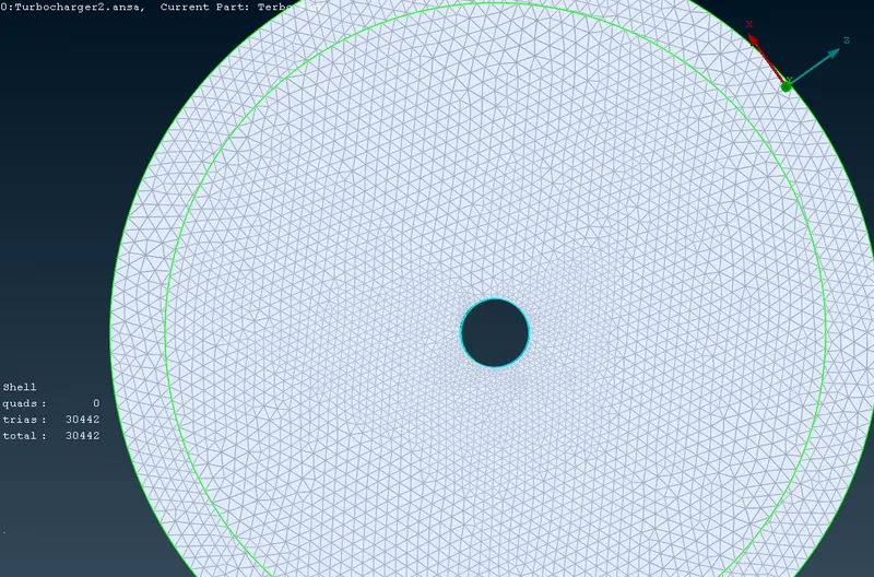
- Surface Meshing of the Compressor Casing surfaces connected with Shaft Rotor.
1) Quality Criteria for Compressor Casing surfaces connected with Shaft Rotor 2) Mesh Parameters for Compressor Casing surfaces connected with Shaft Rotor 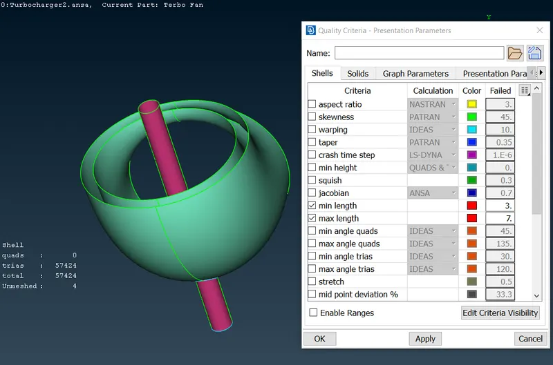
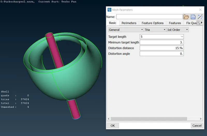
3) Perimeters setting for Compressor Casing surfaces connected with Shaft Rotor under Perimeters>Length>Perimeter 4) Macros setting for Compressor Casing surfaces connected with Shaft Rotor under Perimeters>Length>Macros has been left blank as macro length is varying between 1 to 5 mm. 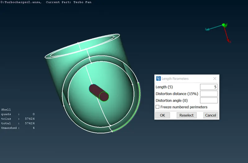
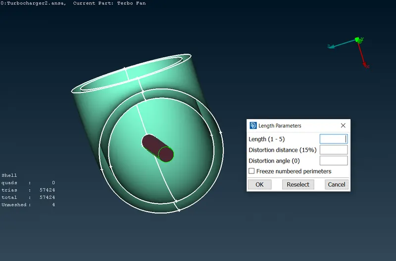
5) Surface Mesh generation for Compressor Casing surfaces connected with Shaft Rotor with Mesh Generation>Spot Mesh>select command. 6) Generated Surface Mesh have been observed as follows. 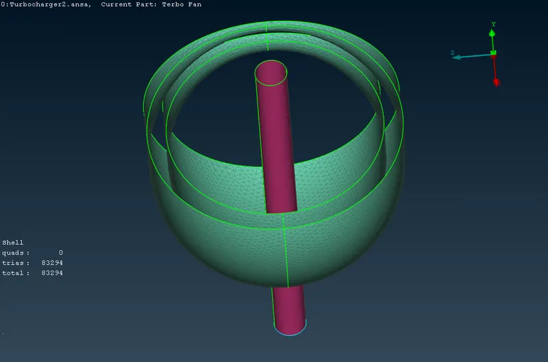
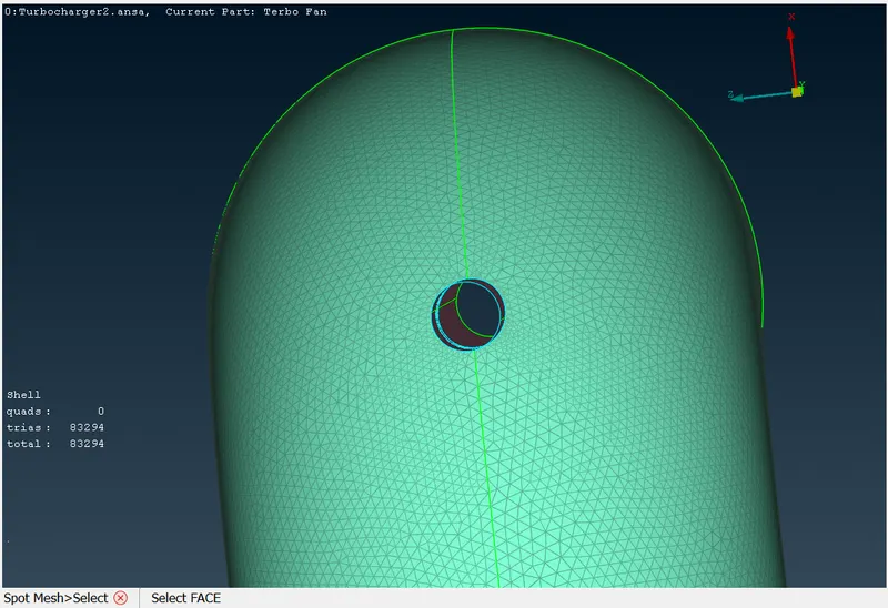
7) Confirmation of all surfaces have been meshed as no unmeshed surfaces listed. 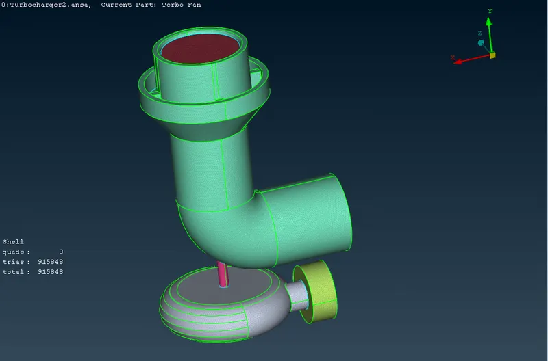
Steps to perform the volumetric meshing with required volumes:
- Auto detection volumes using Volume>Define command with whole database selected.
1) List of auto detected volumes 2) Compressor Casing Internal Volume. It will be retained. 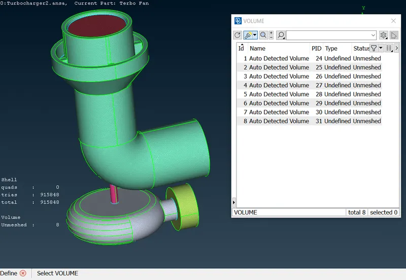
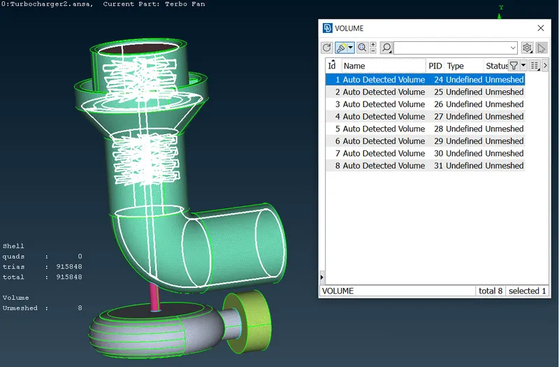
3) Compressor Casing thickness volume. It will be deleted. 4) Turbocharger Casing Internal Volume. It will be retained. 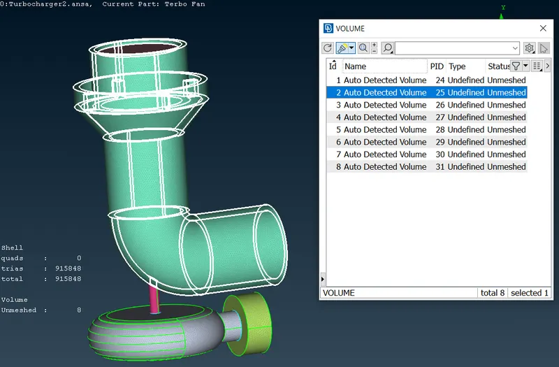
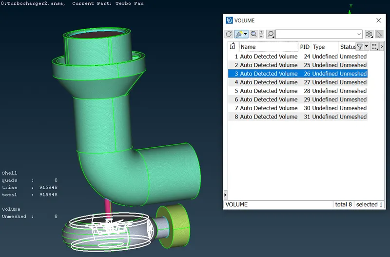
5) Turbocharger Casing thickness volume. It will be deleted. 6) Turbo Inlet Casing thickness volume. It will be deleted. 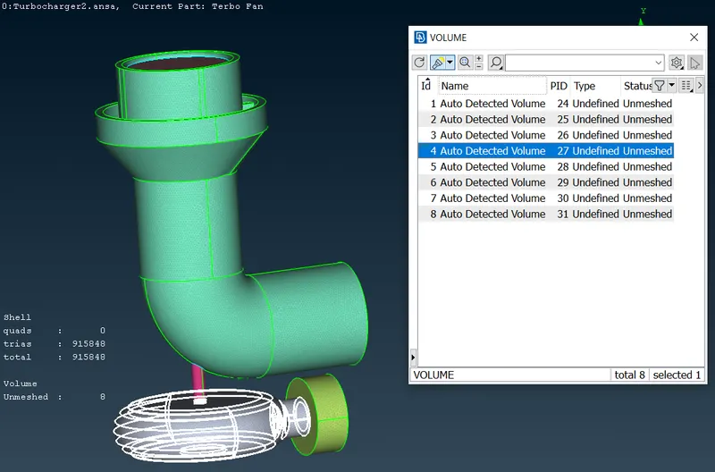
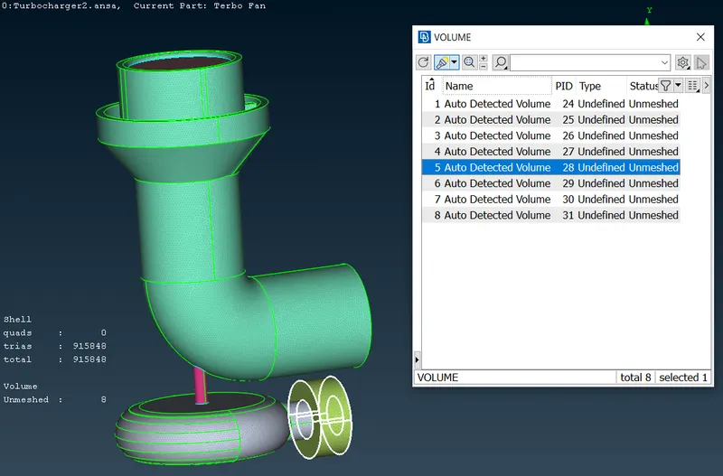
7) Shaft Rotor,Blades and Impeller common volume. It will be deleted. 8) Turbo Inlet Casing and Turbocharger connection volume. It will be retained. 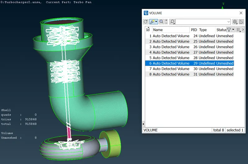
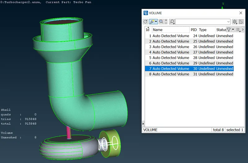
9) Separate small volume in Turbocharger. It will be retained. 10) List of Retained Volumes and Type has been modified to Tetra CFD 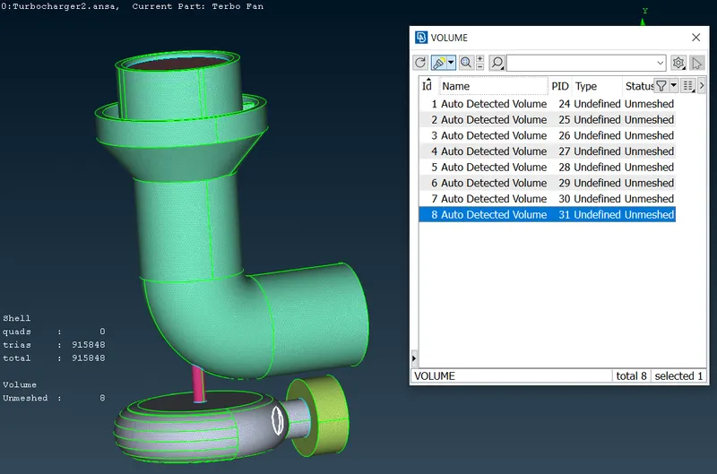
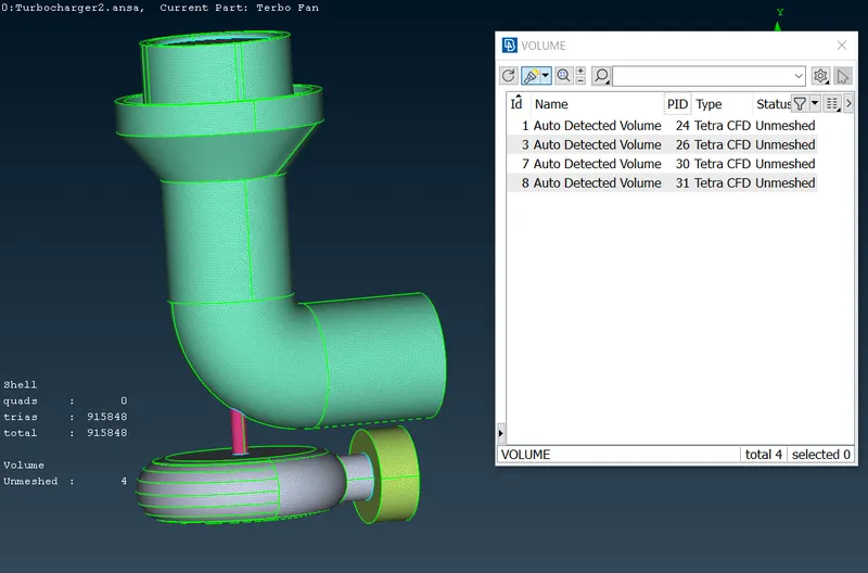
- Volumetric Mesh Generation
1) Volume Meshing of the small internal separate volume at the inlet of Turbocharger. 2) Volume Meshing of the internal volume connecting Turbo Inlet Casing and Turbocharger. 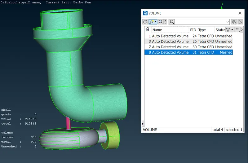
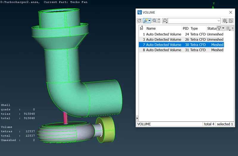
3) Volume Meshing of the internal volume of Turbocharger. 4) Volume Meshing of the internal volume of Compressor. 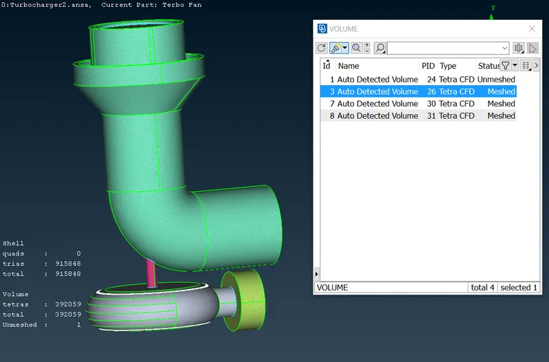
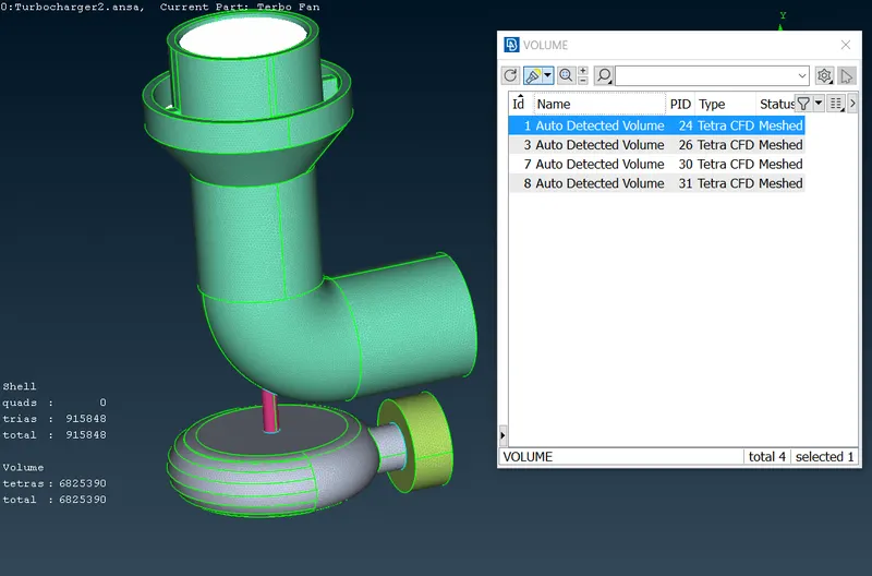
- Volumetric Mesh View
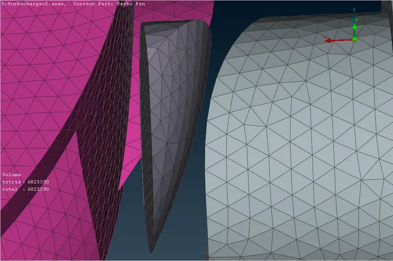
1) Compressor volumetric mesh 2) Turbocharger volumetric mesh 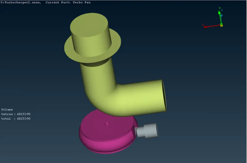
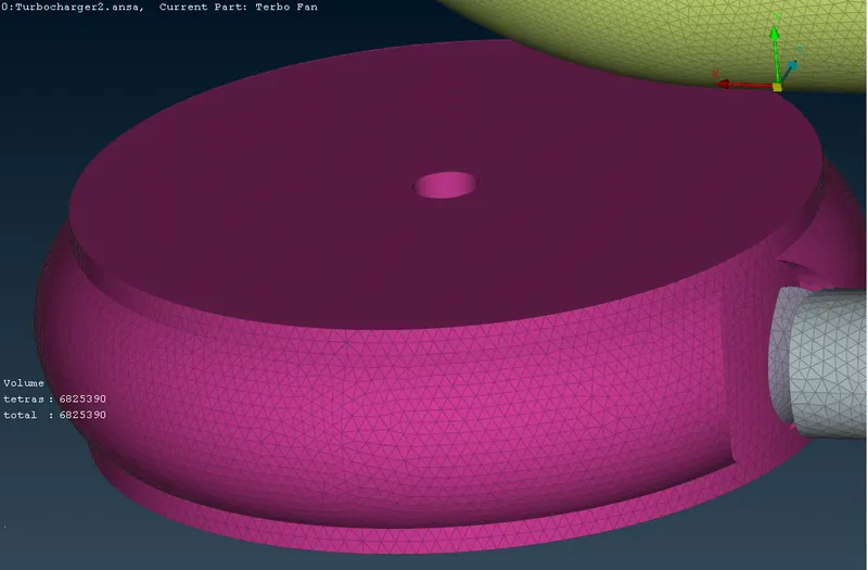
3) Volumetric mesh of Turbo inlet casing and Turbocharger connection 4) Volumetric mesh of small separate volume at Turbocharger. 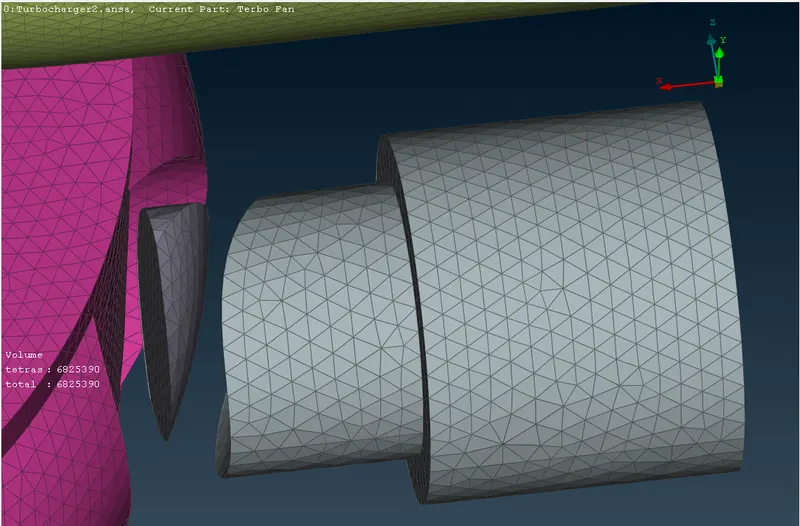
- Volume mesh cross sectional Views.
1) Overall cross sectional view of volumetric mesh 2) Cross sectional view of mesh around Blades Stage_1 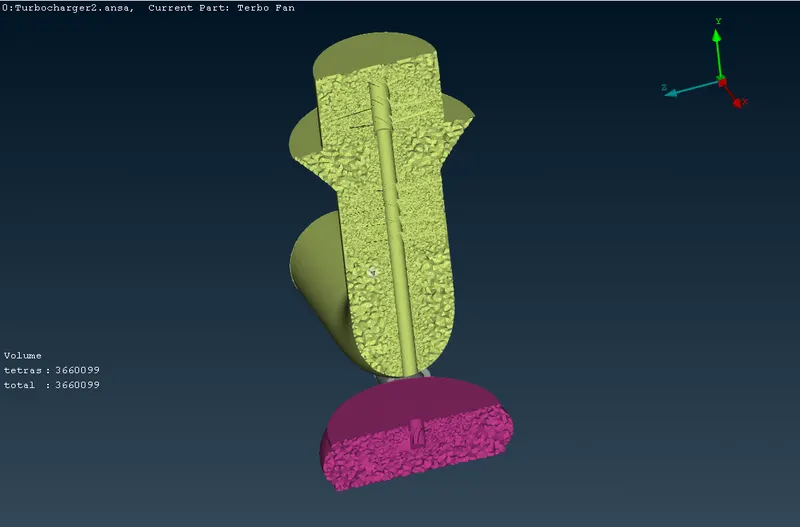
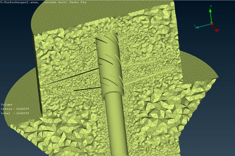
3) Cross sectional view of mesh around Blades Stage_2 4) Cross sectional view of mesh at the entry of shaft rotor into compressor casing. 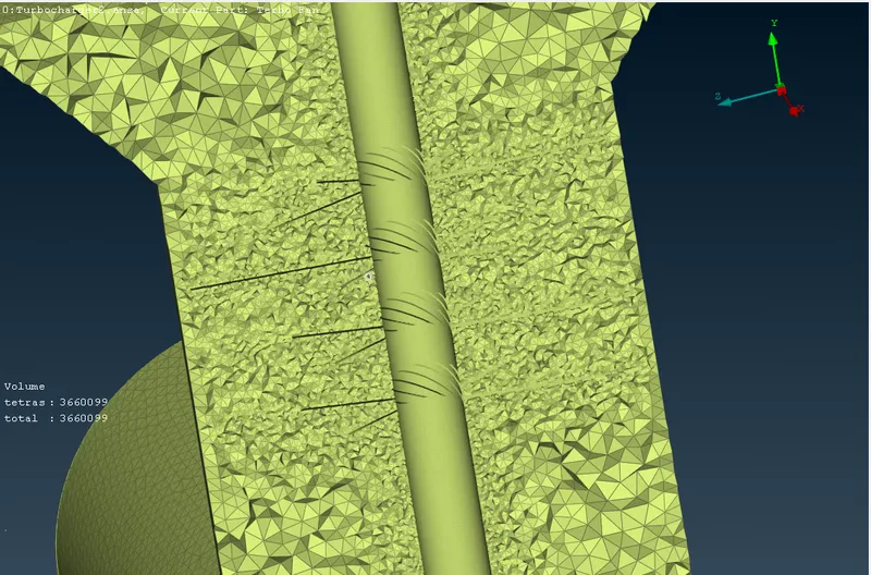
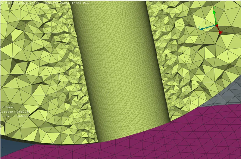
5) Cross sectional view of mesh around Impeller 6) Cross sectional view of mesh at the Turbocharger inlet 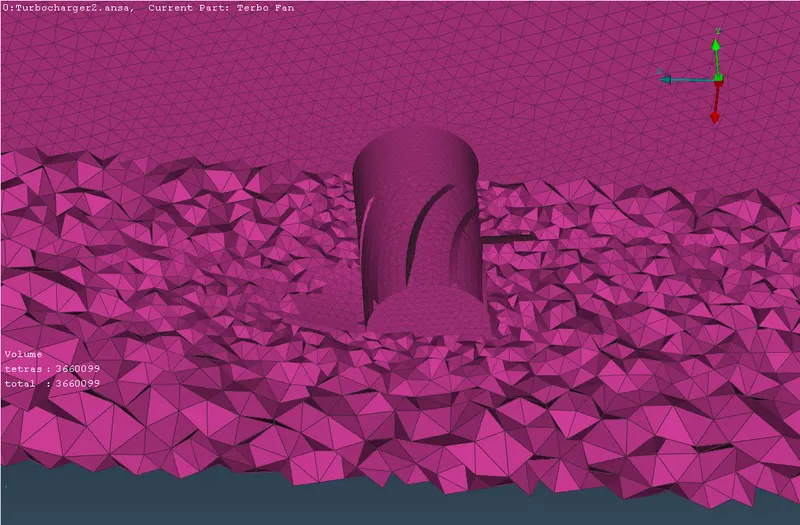
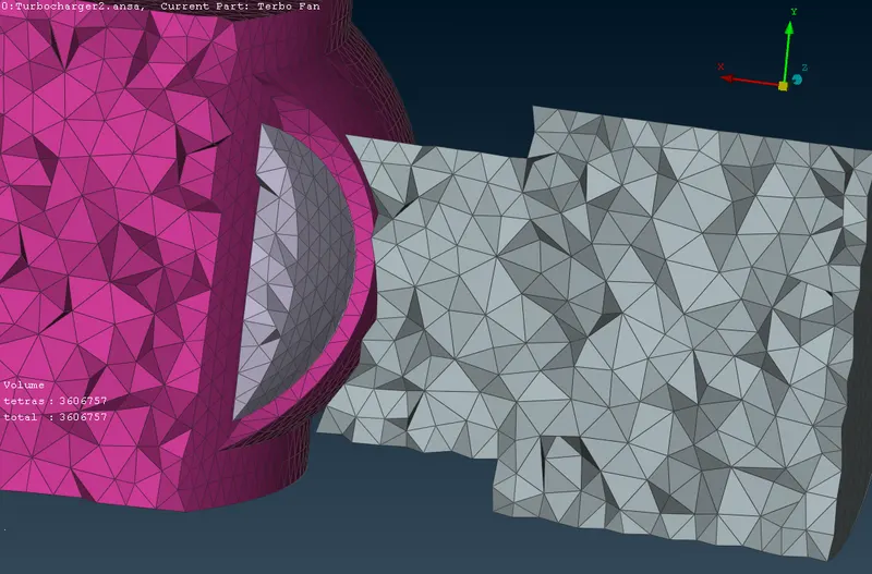
7) Wireframe view of Compressor volumetric mesh 8) Wireframe view of Turbocharger volumetric mesh 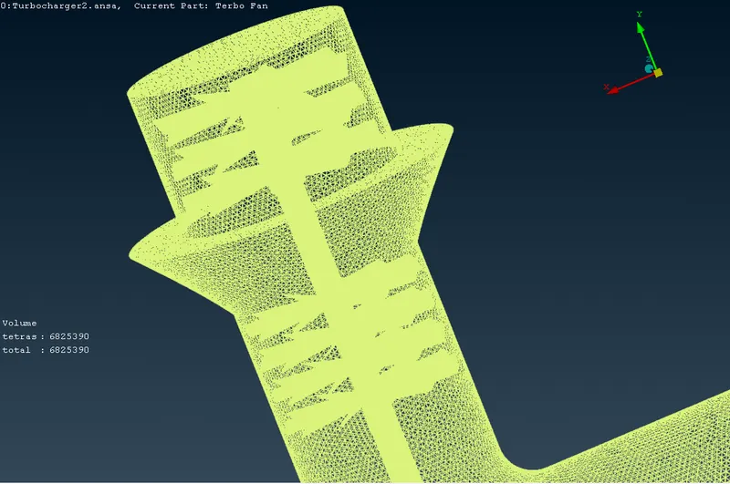
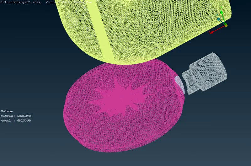
The .rar file of the same model has been attached herewith for the reference.
Conclusions:
- Thus the given geometrical model has been cleaned for errors associated with the model using ANSA.
- Then the model has been surface meshed successfully for the given criteria of the target length with triangular elements using ANSA.
- Afterwards the model has been volume meshed successfully for the required internal volumes with tetrahedral CFD elements using ANSA.
- Procedure of the same has been presented above.