Week 1 : Exploring the GUI of GT-POWER
Aim: To explore the GUI of GT SUITE.
1. To list down the modules available with brief description.
2. To locate following settings:
- Time control flag
- Time step and solution control
- Integrator/Solver type
3. To explore intercooler tutorial and note down all settings of:
- Run setup
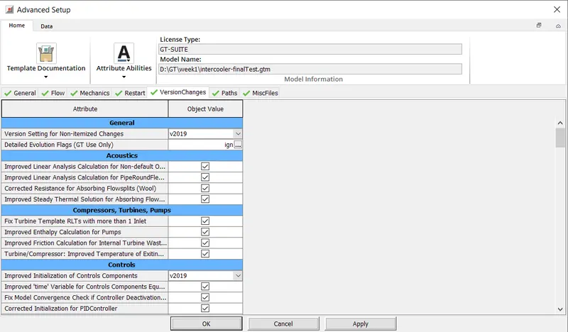
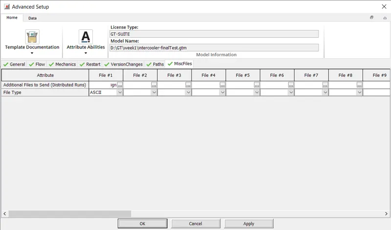
- Advanced setup
- Plot setup
- Output setup
4. To Simulate Problem:
Given
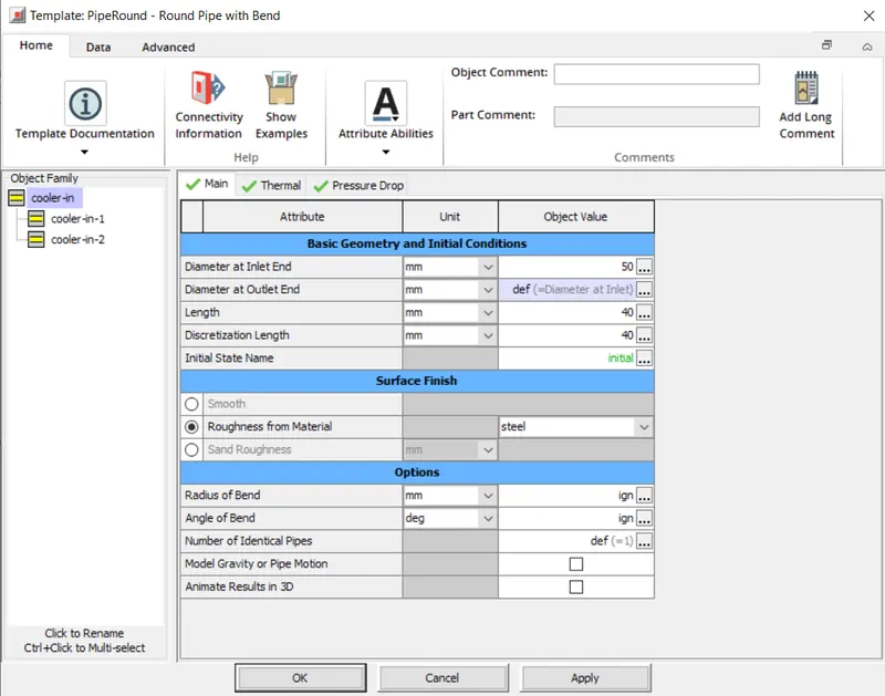
- Diameter of cooler inlet and outlet pipe= 50 mm
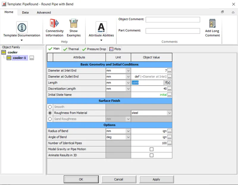
- Length of the CAC= 1000 mm
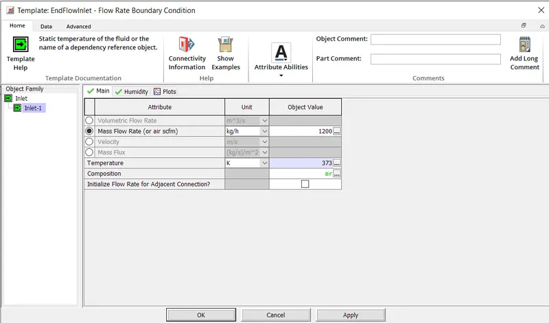
- Inlet mass flow rate = 1200 kg/ h at 100 degC
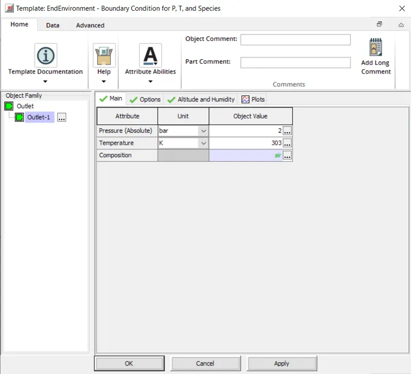
- Outlet pressure 2 bar at 30 deg C
- To calculate the Average heat transfer at Charge air cooler (CAC)
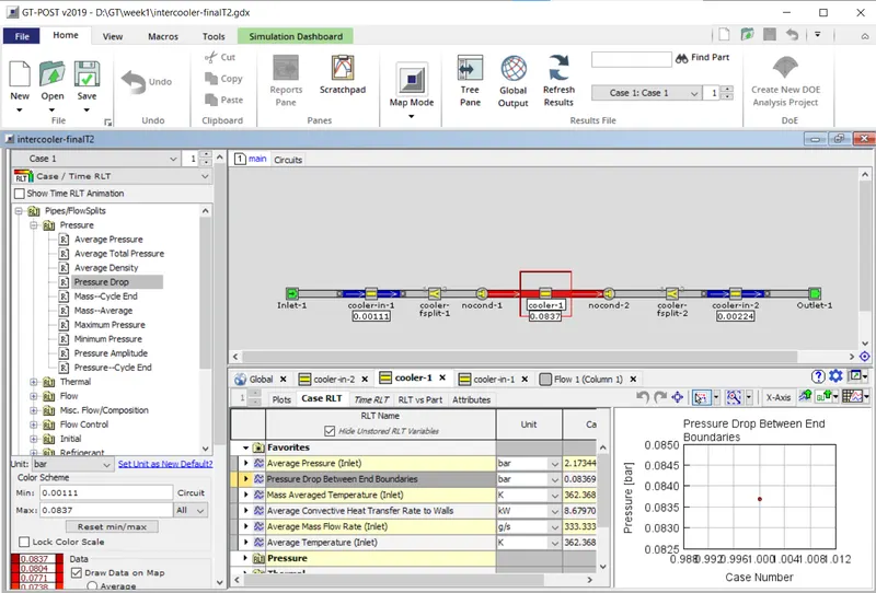
- To calculate pressure drop across CAC.
Solution:
1. List of Modules available with GT-Suite.
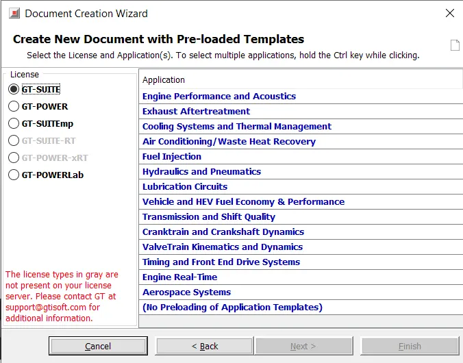
- Engine Performance and Acoustics:
This module is to check the performance of the engine for various parameters along with acoustics. - Exhaust Aftertreatment:
This module is mainly used to analyse the exhaust aftertreatment systems from engine. - Cooling Systems and Thermal Management:
This module is used to analyse the cooling and thermal management systems. - Air Conditioning / Waste Heat Recovery:
This module is used to analyse the air conditioning and waste heat recovery systems. - Fuel Injection:
This module is used to model a different methods and patterns of fuel injections in the engine and analyse the same. - Hydraulics and Pneumatics:
This module is used for modelling of hydraulic and pneumatic systems. - Lubrication Circuits:
This module is used model and analyse the various lubrication circuits from the engine and other machines. - Vehicles and HEV Fuel Economy and Performance:
This module is to model and analyse the different type vehicles and their fuel performances. - Transmission and Shift Quality:
This module is used for modelling transmission systems and their analysis. - Crancktrain and Crankshaft Dynamics:
This module is used to model the crancktrain and their dynamic analysis. - ValveTrain Kinematics and Dynamics:
This module is used to model valve train and their performance analysis. - Timing and Front End Drive Systems:
This module is used to analyse the timing for various systems. - Engine Real Time:
This module is used to do real time analysis of the engine. - Aerospace Systems
This module is used to analyse the various aerospace systems.
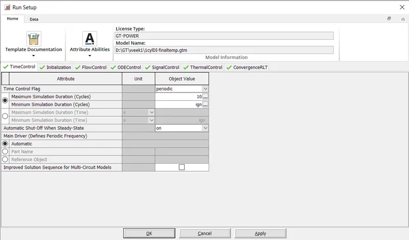
2. To Locate Following Settings:
- Time Control Flag: Run Setup > Time Control > Time Control Flag
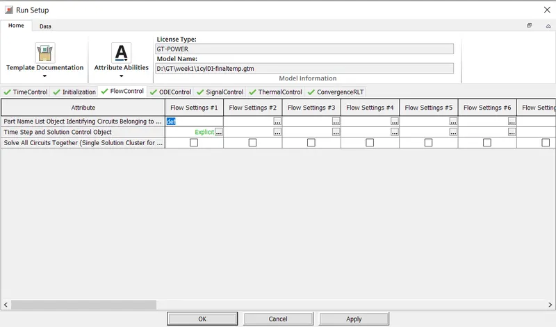
- Time Step and Solution Control: Run Setup > Flow Control / ODE Control > Time Step and Solution Control Object
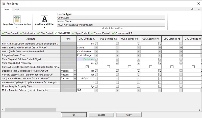
- Integrater/Solver Type: Run Setup> ODE Control > Integrater / Solver Type
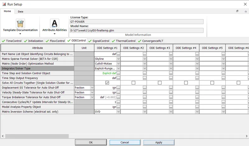
3. Exploration of intercooler tutorial and required following settings from the tutorial:
Search Path: File > Turorials > Engine_Performance > 06-6cylDIturbo > intercooler-final.gtm
- Run setup:
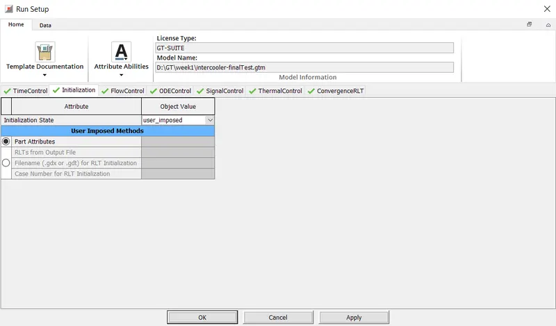
1) Time Control settings 2) Initialization settings 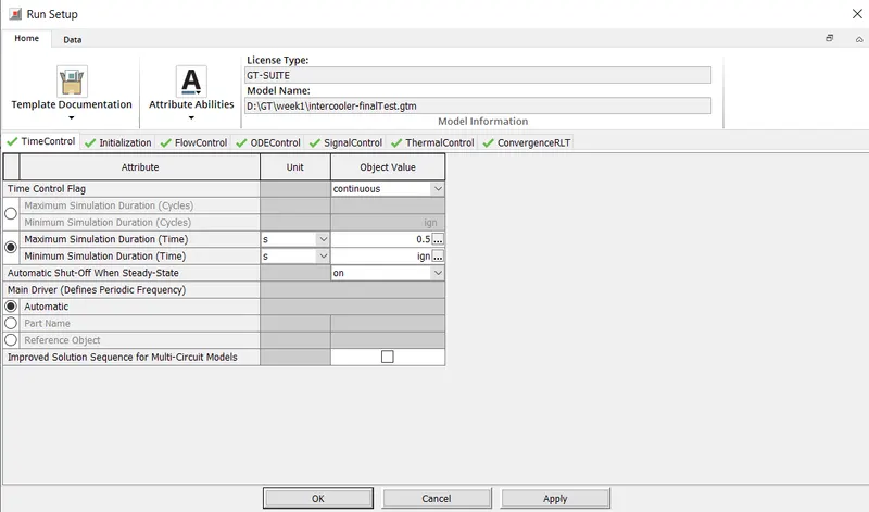
3) Flow Control Settings 4) ODE Control Settings 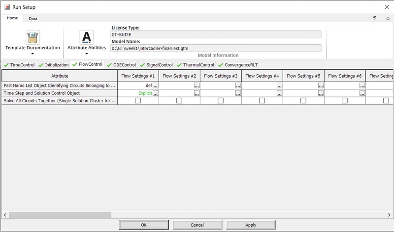
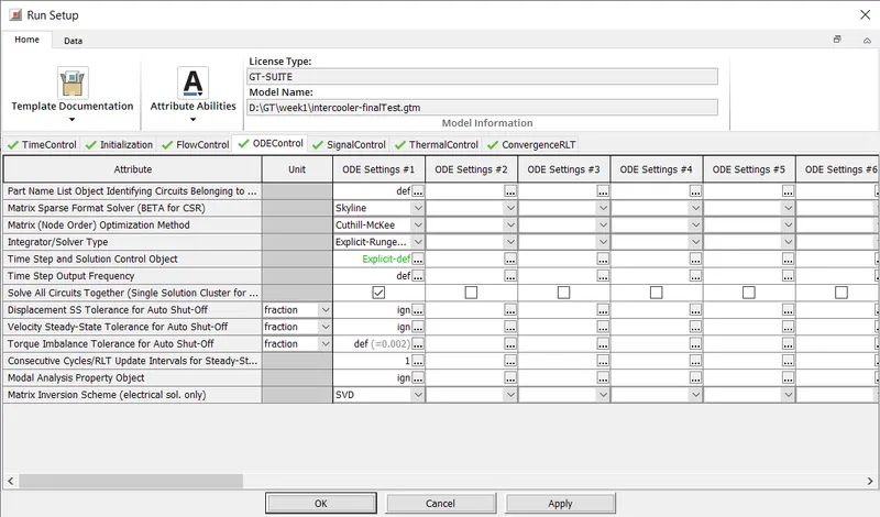
5) Signal Control Settings 6) Thermal Control Settings 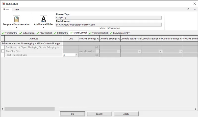
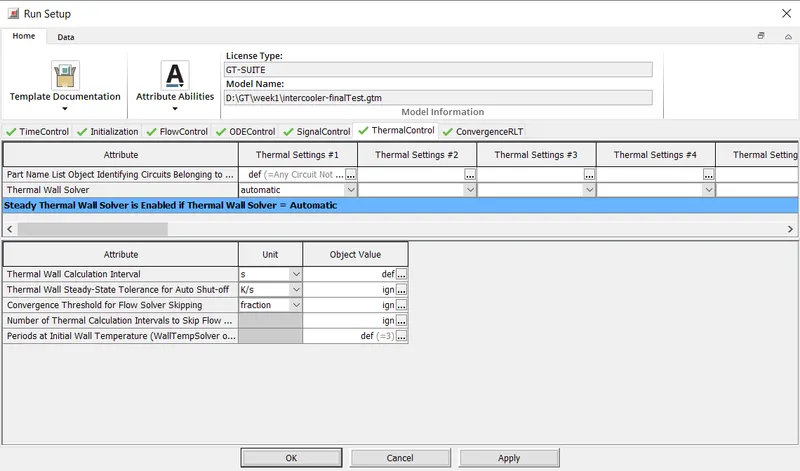
7) Convergence RLT Settings 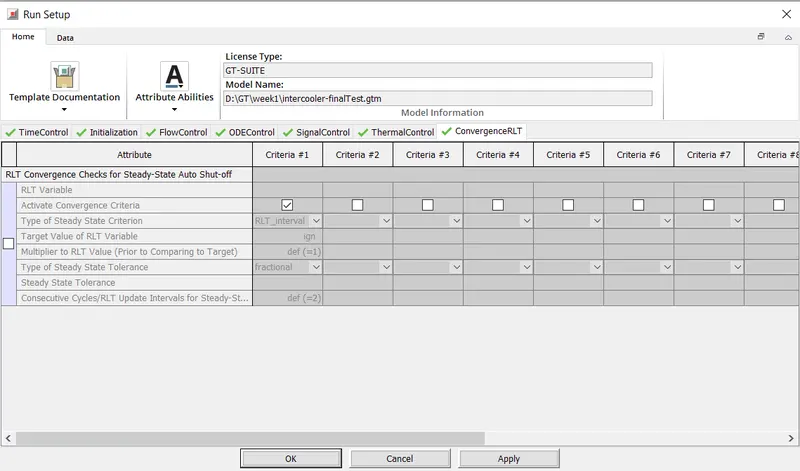
- Advanced setup
1) General Settings in Advance Setup 2) Flow Settings-1 in Advance Setup 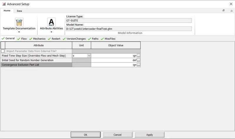
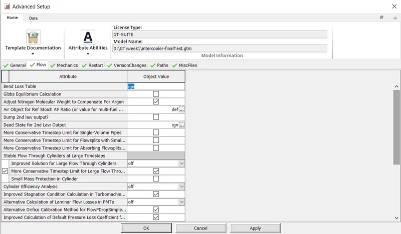
3) Flow Settings-2 in Advance Setup 4) Mechanics Settings in Advance Setup 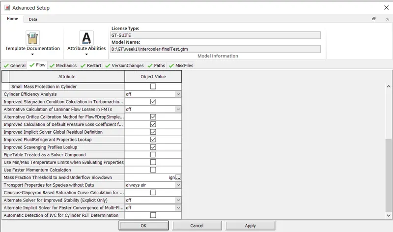
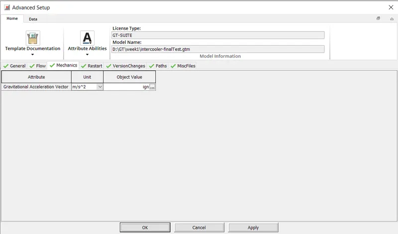
5) Restart Settings in Advance Setup 6) Version Changes Settings in Advance Setup 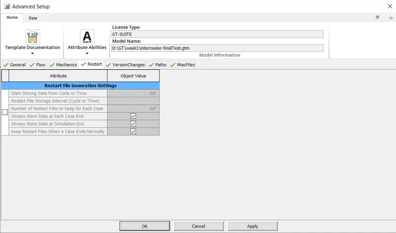
7) Paths Settings in Advance Setup 8) Misc Files Settings in Advance Setup 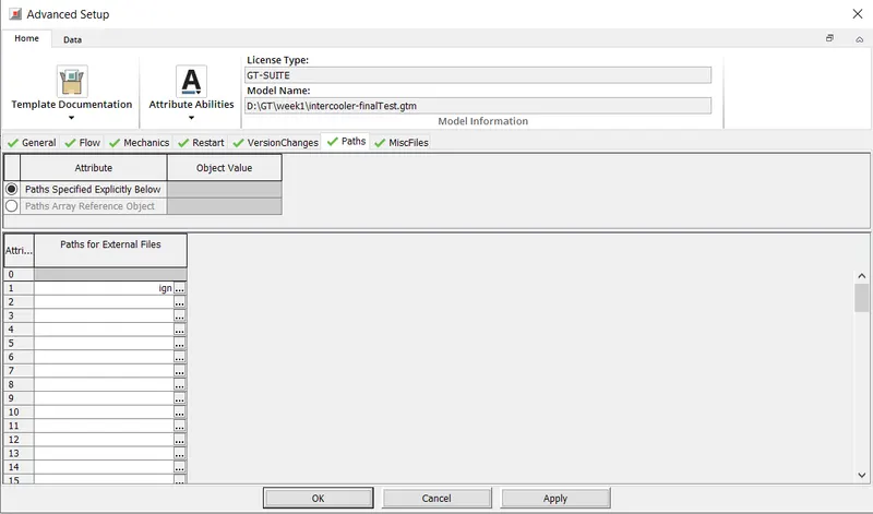
- Plot setup
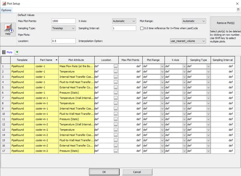
1) Plot Setup 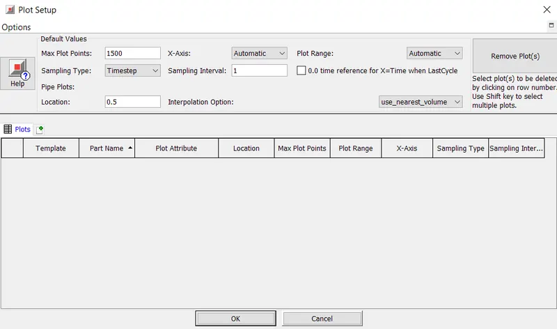
- Output setup
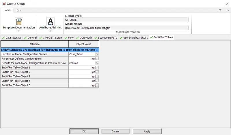
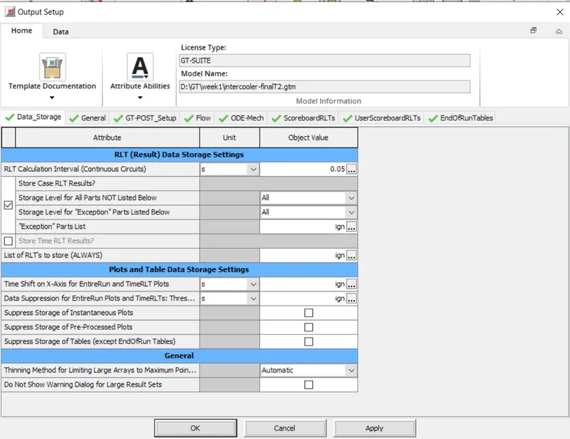
1) Data Storage Settings in Output Setup 2) General Settings in Output Setup 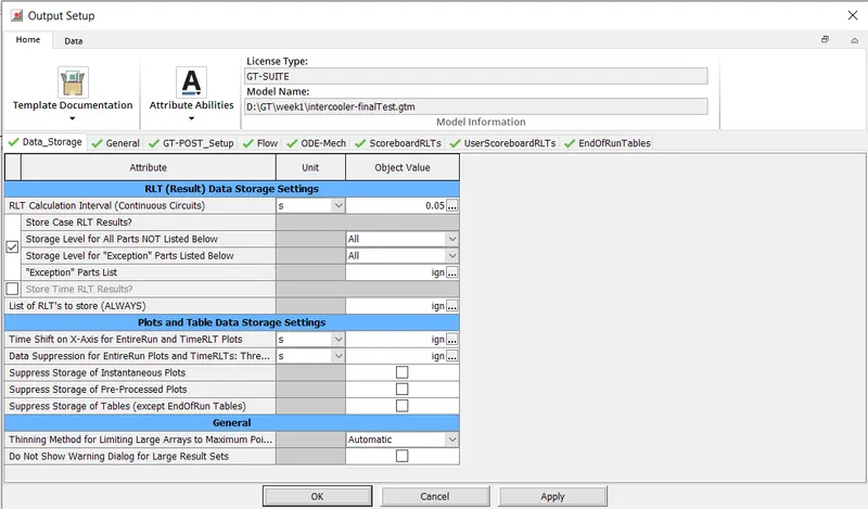
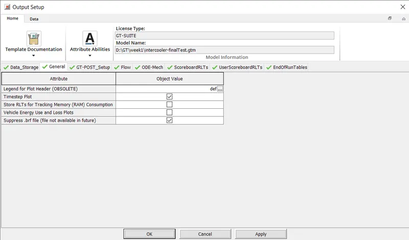
3) GT Post Settings in Output Setup 4) Flow Settings in Output Setup 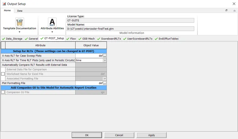
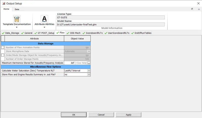
5) ODE Mech Settings in Output Setup 6) Scoreboard RLTs Settings in Output Setup 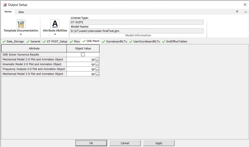
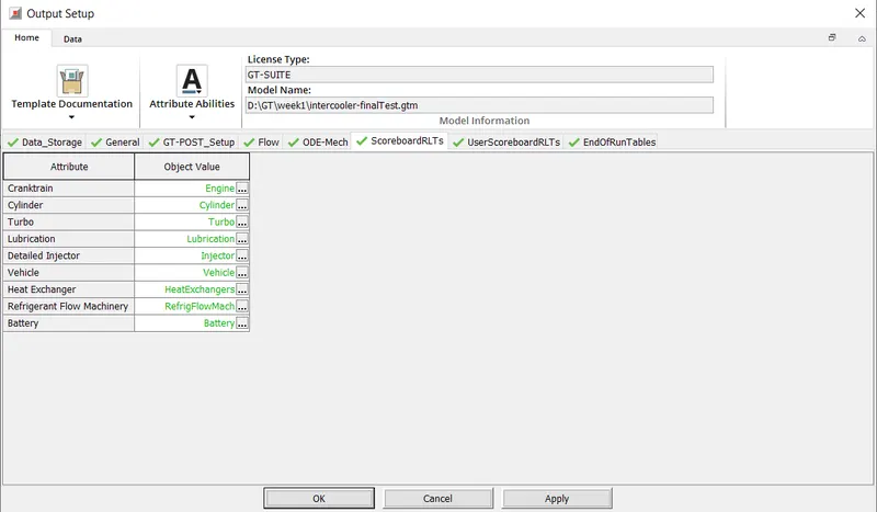
7) User Scoreboard RLTs Settings in Output Setup 8) End of Run Tables Settings in Output Setup 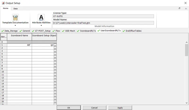
4. Solution to the given CAC problem:
| 1) | CAC Inlet mass flow rate and temperature value selection | 2) | CAC inlet and outlet diameter value selection | |
 |
 |
|||
| 3) | CAC Pressure drop settings | 4) | CAC length value selection | |
 |
 |
|||
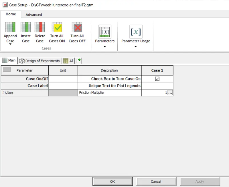
| 5) | CAC outlet pressure and temperature value selection | 6) | Case setup | |
 |
 |
|||
| 7) | Plot Setup | 8) | Data Storage setting from Output setup | |
 |
 |
|||
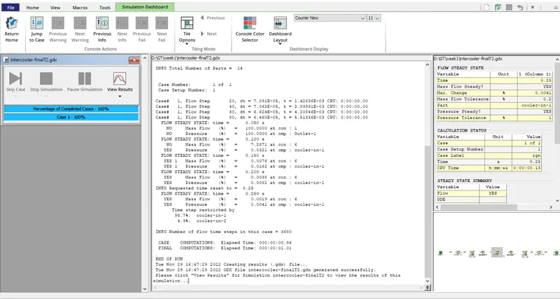
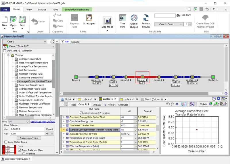
| 9) | GT Post while Simulation Running | 10) | CAC average heat transfer rate | |
 |
 |
|||
| 11) | Pressure deop across CAC | 12) | ||
 |
1) CAC Average Heat transfer rate is around - 8.68 kW. |
|||