Week - 4 - crash box simulation
Objective :
To create an impact analysis on a given model box with the help of a rigid wall and to see the stress, strain and energy values when box impact on the rigid wall.
Procedure :
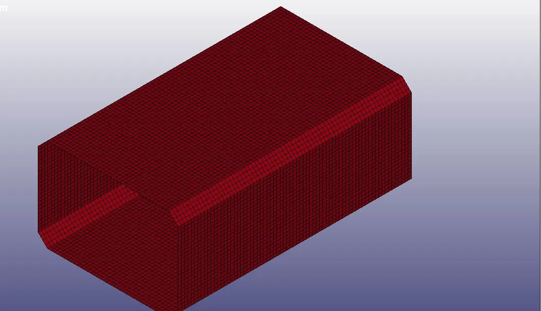
Step 1: Import the Box model which is in .k format to the Ls pre post and change the title which is in keyword manager.
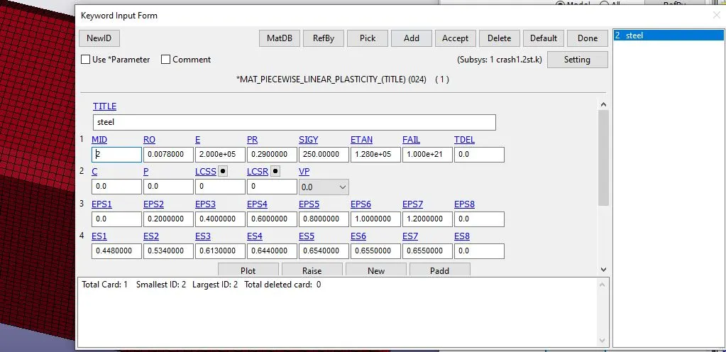
Step 2: Now we have to create a impact boundary conditions for the box to do that first we need to create a material id for the given model. Here we are taking the steel material properties for the box and convert the property values into the gm mm ms and accept it.
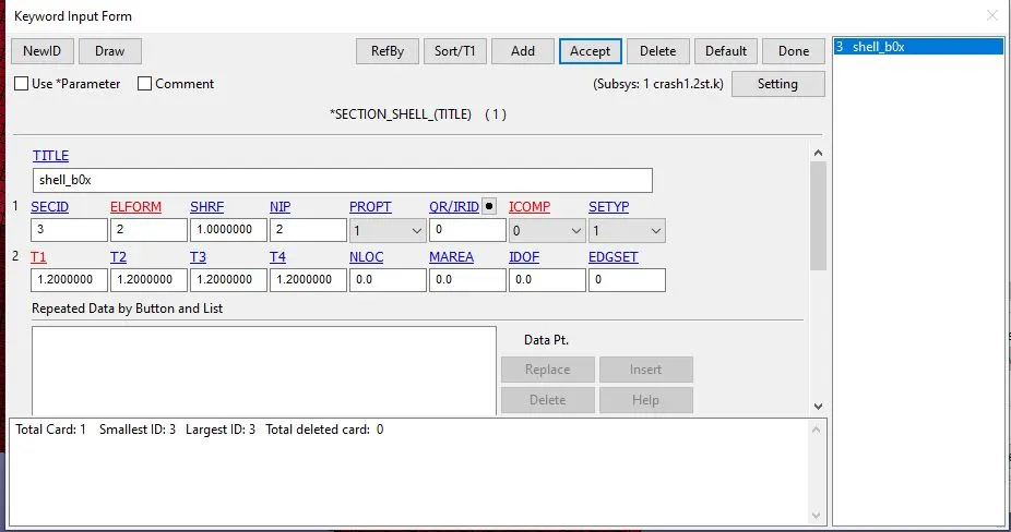
Step 3: Now create a shell id for the box model mesh and there give the thickness od 1.2mm for the shells.
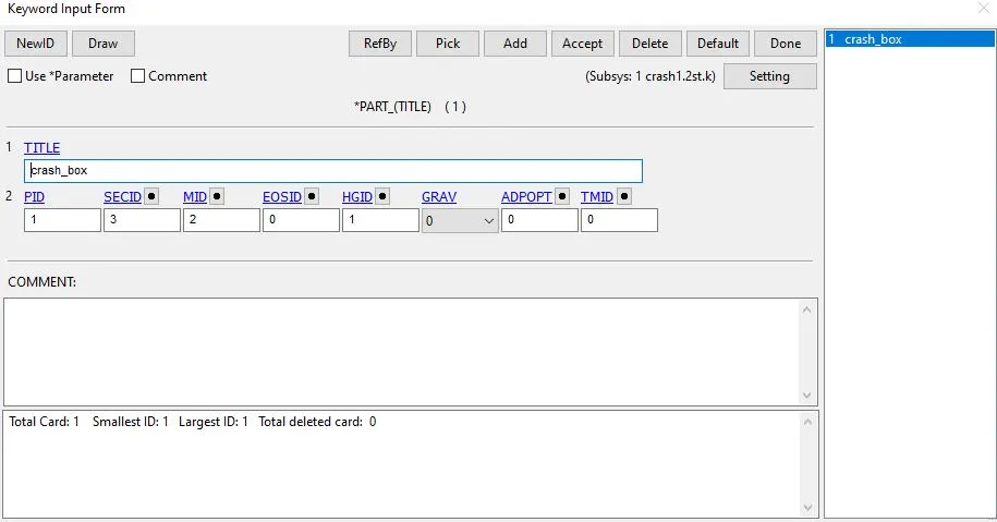
Step 4: Now go to the part keyword and give the material and shell id and accept it. Thus the box model has the material and shell property.
Step 5: To create a impact for the box we need to create a rigidwall and the intial velocity for the box. To create rigidwall go to the create entity and select the rigidwall and select the planar option and with the help of N1, N2 nodes we can create a rigidwall for the box and accept it.
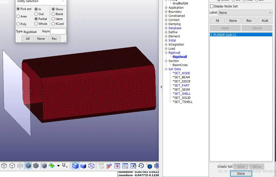
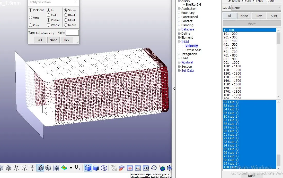
Step 6: Now go to the intial option in create entity and pick the whole area of the box and give the velocity of -13.888 mm/ms(50kmph) in x-direction. Here we gave negative direction because the box wants to hit the rigidwall. Here we need to give a node set id for the to create that go to the set option in create entity and pick the box area and accept it.
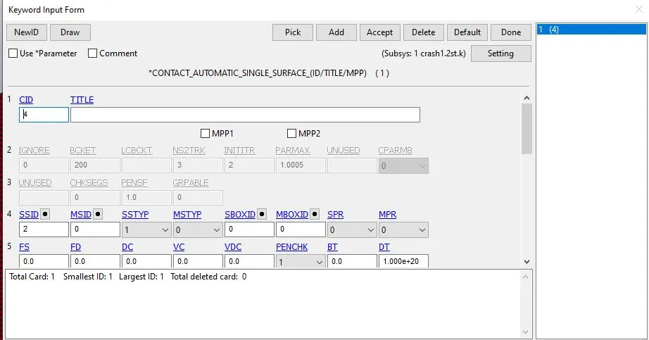
Step 7: Now we have the material and condition to move the box but when we hit the wall there needs to be some contact without that stress are not created. To create a contact boundary go to the keyword manager and select the contact option and we have only single surface of box so select the automatic single surface option and before accepting it we need to give a slave id for this so create a slave id in create entity > set > set sheell, now accept the contact boundary.
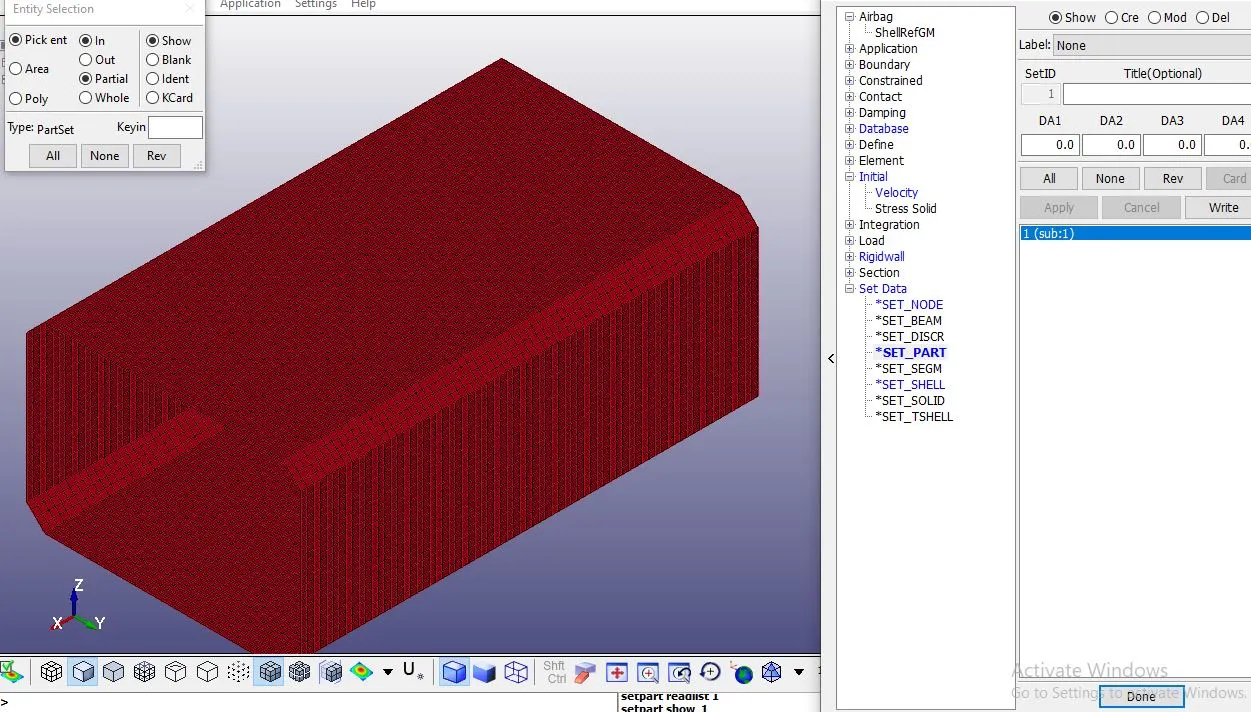
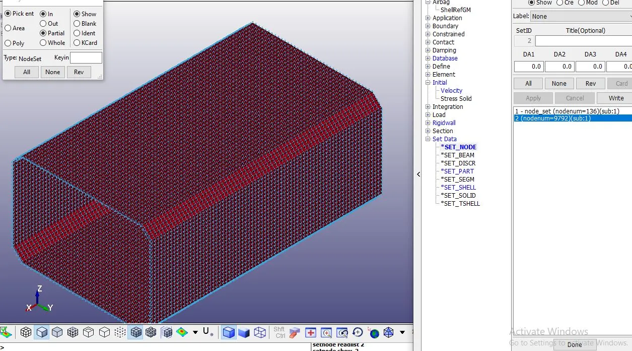
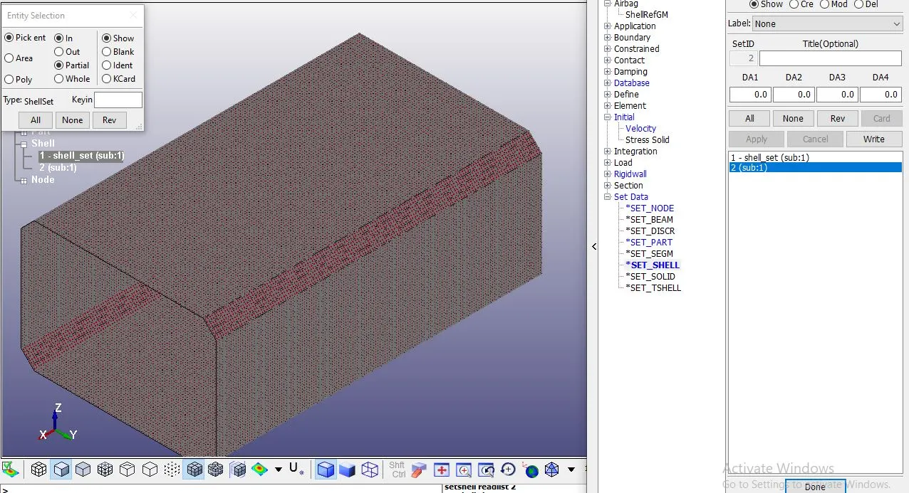
Step 8: Now we have to create another set od node set id and shell set id, these set has middle section of box which will help to calculate the middle force of the crash box.
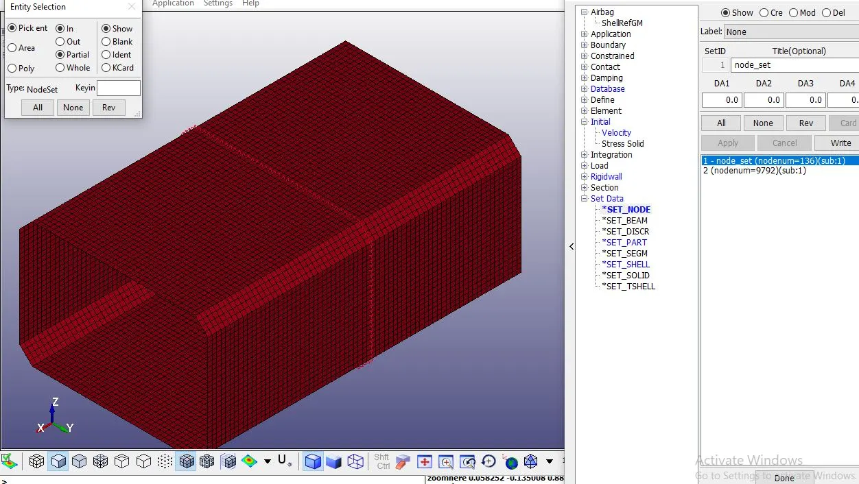
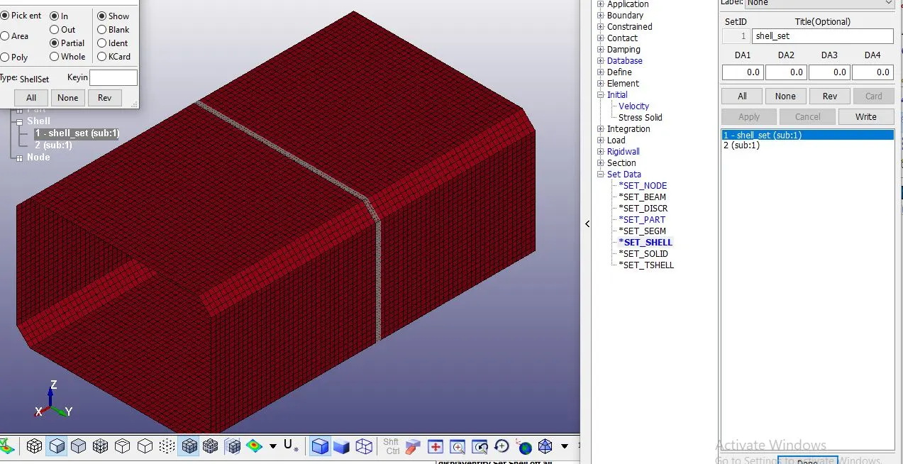
Step 9: Now we have all boundary conditions for the box but we don't have the results to extract, to do that we need to create a ascii option and binary d3plot, crrosect set and history node set these are the databases for our crash box and also helpful to calculate the middle forece and accelerations of the crash box.
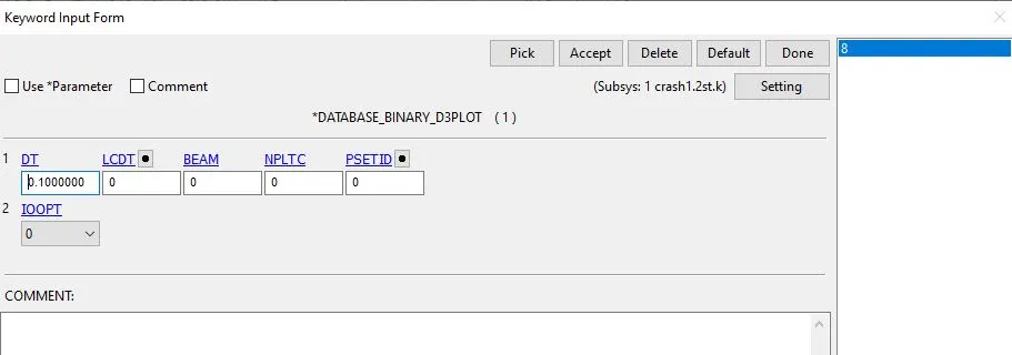
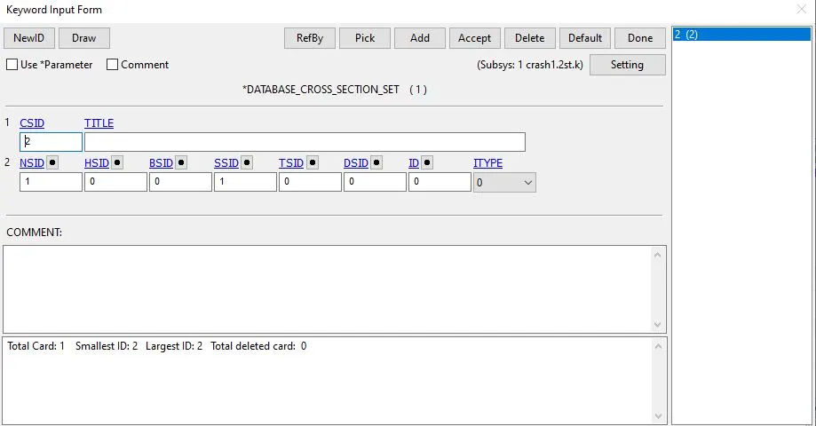
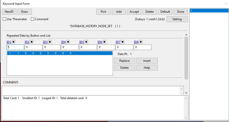
Step 10: Now we need to create a termination for the analysis so go to the contro option and create a termination id for the box and also create a energy and hourglass id. Save the file .k format.
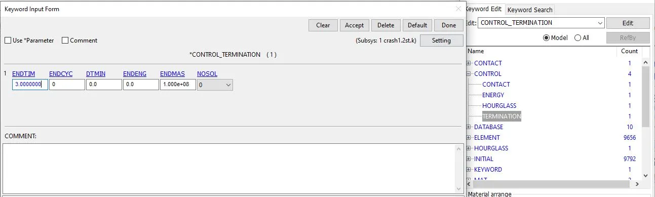
Step 11: Everything is completed in the pre processing now we need to solve the problem go to the ls manager and select the .k file and run the file and the file ends with the normal termination then our analysis is correct.
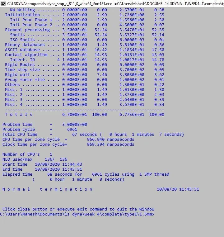
Step 12: Now open the new tab in ls prepost and open the d3plot and check the stress values for the analysis. Like this we need to create a 1.5mm analysis for the crash box, same steps for the 1.5mm crash box.
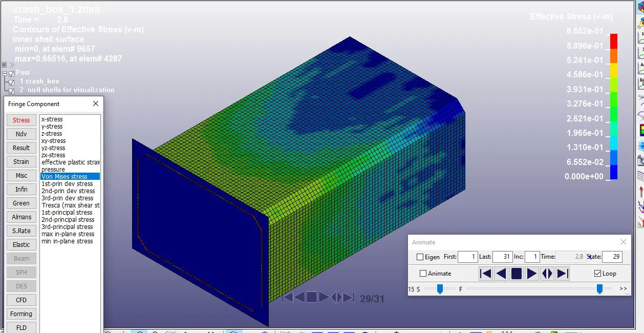
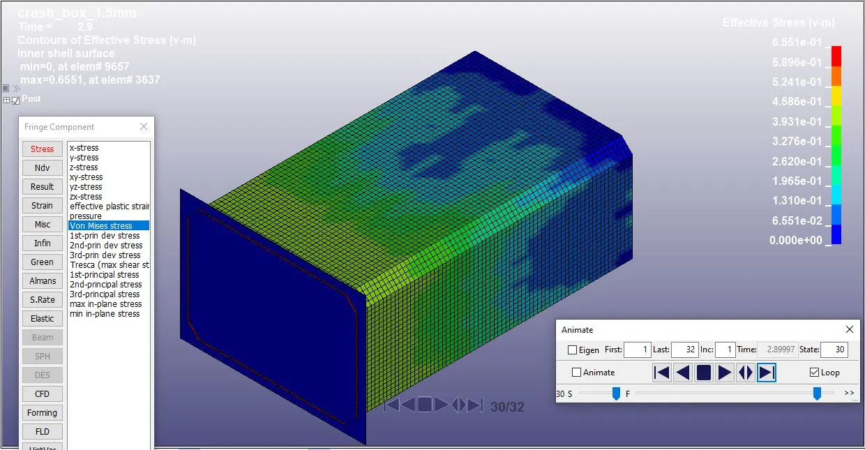
From the model we can clearly see that maximun stress occurs at the element 4287 and has 0.65516 Mpa and it is same for the 1.5mm crashbox model.
Step 13: Finding the force generated at the middle of the crash box.
To plot the sec force open the ascii option and select the secforce and load the file and selct the x direction and select the plot.
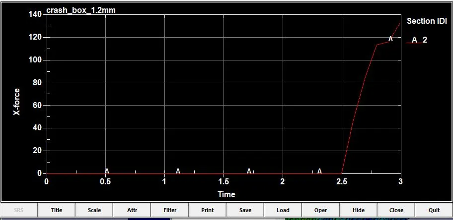
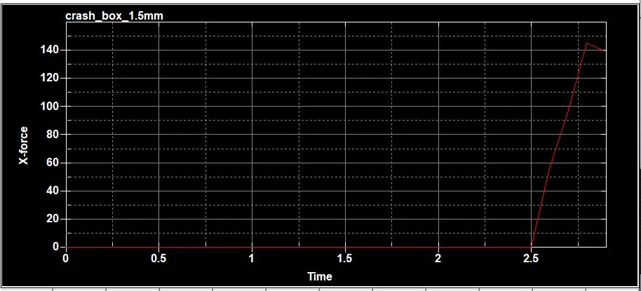
As we can see both the graphs has same type of plot where the force generated at the middle section of the crash box is zero and after the crash box imoacts the rigidwall at the time of 2.5ms we can see the spike where the force is generated due to the impact and goes to the optimal state. Both the plots has maximum force of approximately 140N.
Step 14: Finding the acceleration at the middle of crashbox.
To plot the acceleration or to find that we need to plot the graph using the nodeout and load the file and select the X,Y annd Z direction of accelerations and plot them.
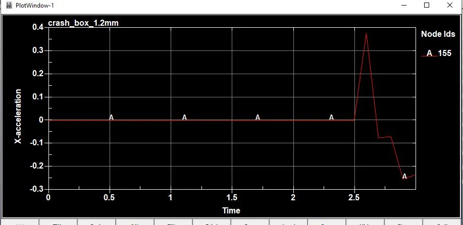
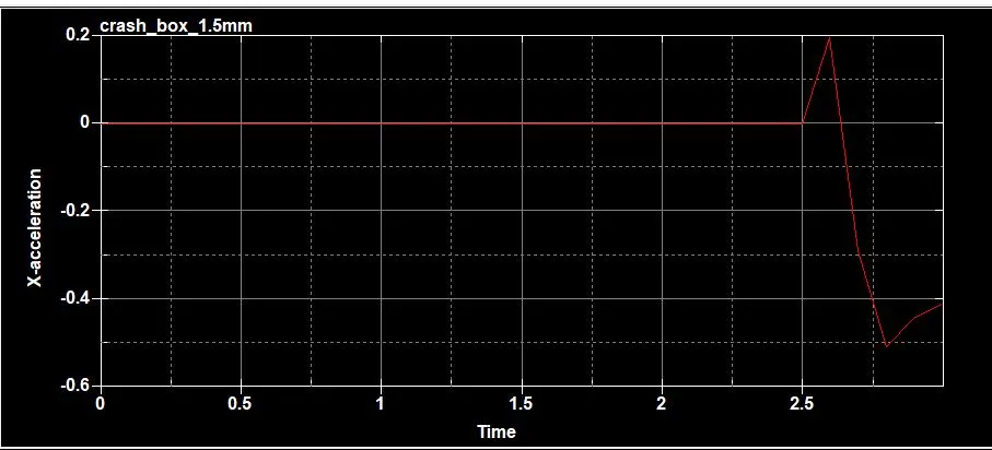
As we can see the graph acceleration of node is increased when the crashbox is impacted to the rigidwall and gradually decelerates. Maximun acceleration for 1.2mm is 0.4mm/ms2 and for 1.5mm is 0.2mm/ms2. When compare the both graphs we can clearly see that the 1.5mm crash box has the less acceleration compared to rhe 1.2mmm crashbox this is due to the resistance by the crashbox which is thick compared to 1.2mm crashbox.
Step 15 : Ploting the energy valus of crashbox using the glstat option for both the 1.2mm and 1.5mm crashbox.
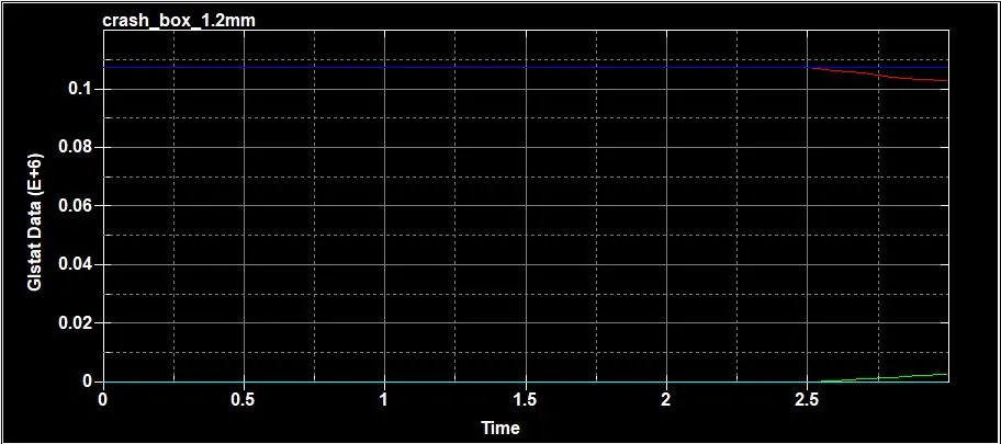
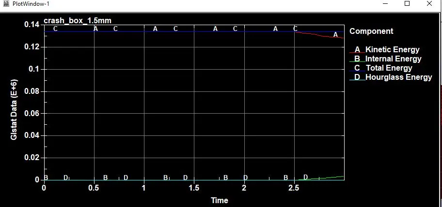
Here we can see that energy generated or conversed between the two type of crash box is different at 1.2mm crash box energy gemerated is less when compared to the 1.5mm crash box, this is because 1.5mm absorbs more energy.
Conclusion :
Thus we have created a simulation for the crash box using two different thickness and extracted the results like middle force, acceleration, stress and the energy values.