Project 1
Objective :
To create a midsurface for car dashboard and create mesh to the mid surfaced dashboard in the ANSA software.
I. Import the model to Ansa software and check the geomentry.
II. Create mid surface for the given object.
III. Give pid for the ribs and parts of the dashboard model.
IV. Mesh the given component with quality criteria.
V. Clear the off elements and turn mesh as solids.
Theory :
Introduction for a car dashboard :
A dashboard (also called dash, instrument panel (IP), or fascia) is a control panel usually located directly ahead of a vehicle's driver, displaying instrumentation and controls for the vehicle's operation.
Car industry plays an important role as the back bone for the economy of any country.
Dash board is one of the main parts of the car interior component and plays a very important role in different aspects such as safety, reliability, user friendly, technology
and appearance and so on. Dash board used for operating different functions in the car
such as instrumental panel, audio and video devices, holders, switches and glove box,
these function distributed inside a vehicle that communicate with each other. Car dash
board like the other components of the car have lots of improvement in terms of
quality, extra features, material, updating the existing product to take the dash board
at the new level. Around 1960’s, the car dash board was designed basically form
cheap material and with limited features, but now we can see that modern design and
more features is very basic requirement for any type of car.
Types and features of a dashboard :
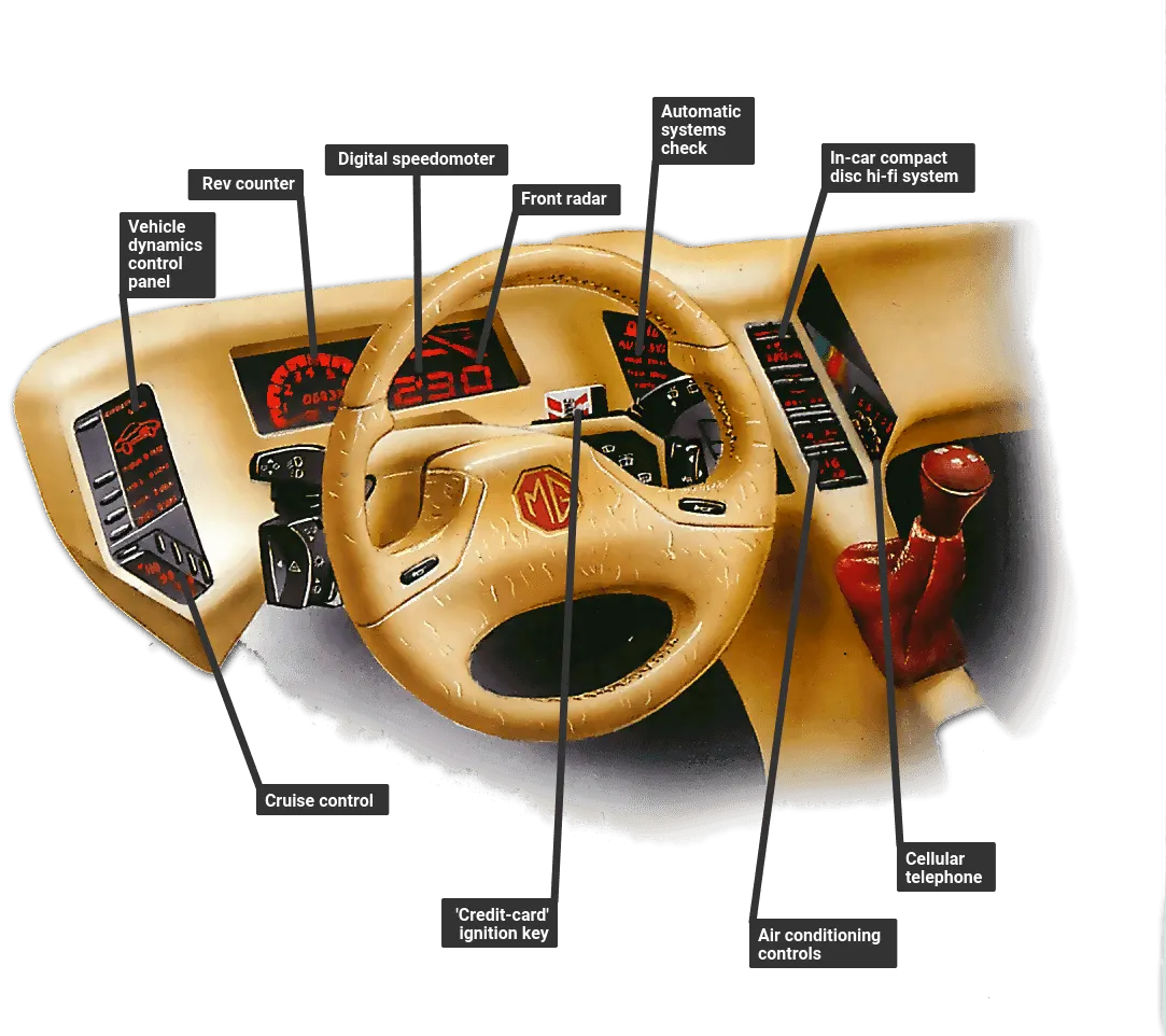
On a modern car, the dashboard is made from moulded plastic, often as a one-piece unit with all the necessary spaces and ducts for the heating system, instruments, radio-cassette units and speakers. Moulded plastic gives the car designer much greater freedom in dashboard styling, both for driver safety and customer appeal.
But the greatest change is in the range of instruments you can find on a car nowadays, and the way in which they are displayed.
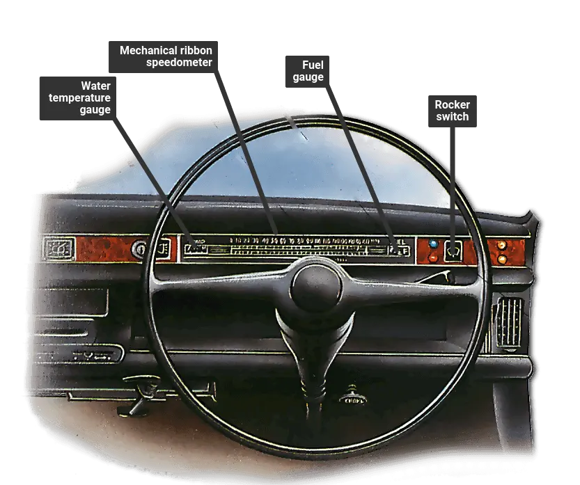
As well as those on a car from 25 years ago (except the ammeter has now largely been replaced by the voltmeter or battery condition indicator) modern top-of-the-range models often have a variety of warning lights and checks to monitor the car's various systems.
Electronic dashes

Much of the information that a modern dashboard can give the driver has been made possible by the electronics revolution over the past ten years or so. Electronics has also influenced dashboard displays.
Many cars now have digital speedometers that display their information either as a changing figure or as a diagram, showing the engine speed climbing up a graph as it rises. Once you are used to this sort of display, it is very easy to register the figure for the car's speed, instead of having to note the position of a needle on a dial as on the old speedometer.
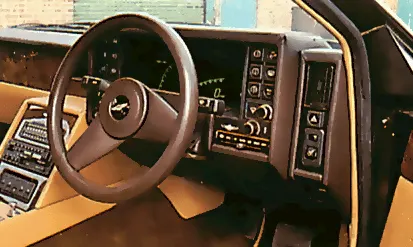
Supplementary instruments have changed too. Gone are the pointer needles and in place are bar graphs giving information readout.
Radio information
Another likely future development is radio-based information systems. One of these, already under review in Germany, consists of transmitters which give information about road conditions.
At the moment, the system works only when the radio is on —the transmitters override the programme to give information. But, with a suitable radio, a signal from the transmitter could automatically turn the radio on to warn the driver about impending difficulties.
On-board maps
Philips are currently developing a system that allows you to store maps on compact video disc.
The system consists of a compact video disc player and a TV screen. The disc with the appropriate maps for that country are loaded in. The driver can then select an area and see exactly where he is and where to go. The system keeps a track of where the driver is on the map.
Early attempts at the electronic dash were regarded as a gimmick more than anything else. These instrument packs usually employed LED ( light-emitting diode ) displays, which were difficult to read if caught by bright sunlight, and were generally of rather poor quality.
Research developed the newer vacuum-fluorescent displays, which give a much clearer readout. These are used in many new cars, such as the latest Jaguars.
But LED displays are making a comeback. The electronic dash in the latest Vauxhall Astra uses a new way of driving the LED display to make it work better than the old LEDs. Renault, on the other hand, have chosen to use an LCD (liquid-crystal display) in their 21.
Computer control
One of the advantages that all these dashes have is that they can be readily linked into an on-board car computer and cruise-control. This means that all the information required can be displayed on the one panel, rather than having it scattered around the dash.
Since having all the information possible on the screen would make the display difficult to read, only the most important information will remain on the screen all the time. Extra data will be called up and displayed when necessary.
With high-tech electronic dashboards, the trend is towards having an electronic check system - with fewer separate instruments. The check system constantly monitors important functions and gives the driver a warning if any of them is about to fail.
Rather than just displaying a warning light, a check system can distinguish between different degrees of danger in the malfunctions they detect, and react accordingly. Audi use a such a system on many of their latest models.
Future trends
It is likely that the appearance of instruments in the future will be influenced by fashion as much as by function. The real change will probably be in the reduction in the number of wires which feed them.
What Is Finite Element Mesh Refinement ?
Engineers and scientists use to build predictive computational models of real-world scenarios. The use of FEA software begins with a computer-aided design (CAD) model that represents the physical parts being simulated as well as knowledge of the material properties and the applied loads and constraints. This information enables the prediction of real-world behavior, often with very high levels of accuracy.
The accuracy that can be obtained from any FEA model is directly related to the finite element mesh that is used. The finite element mesh is used to subdivide the CAD model into smaller domains called elements, over which a set of equations are solved. These equations approximately represent the governing equation of interest via a set of polynomial functions defined over each element. As these elements are made smaller and smaller, as the mesh is refined, the computed solution will approach the true solution.
This process of mesh refinement is a key step in validating any finite element model and gaining confidence in the software, the model, and the results.
The Mesh Refinement Process
A good finite element analyst starts with both an understanding of the physics of the system that is to be analyzed and a complete description of the geometry of the system. This geometry is represented via a CAD model. A typical CAD model will accurately describe the shape and structure, but often also contain cosmetic features or manufacturing details that can prove to be extraneous for the purposes of finite element modeling. The analyst should put some engineering judgment into examining the CAD model and deciding if these features and details can be removed or simplified prior to meshing. Starting with a simple model and adding complexity is almost always easier than starting with a complex model and simplifying it.
The analyst should also know all of the physics that are relevant to the problem, the materials properties, the loads, the constraints, and any elements that can affect the results of interest. These inputs may have uncertainties in them. For instance, the material properties and loads may not always be precisely known. It is important to keep this in mind during the modeling process, as there is no benefit in trying to resolve a model to greater accuracy than the input data admits.
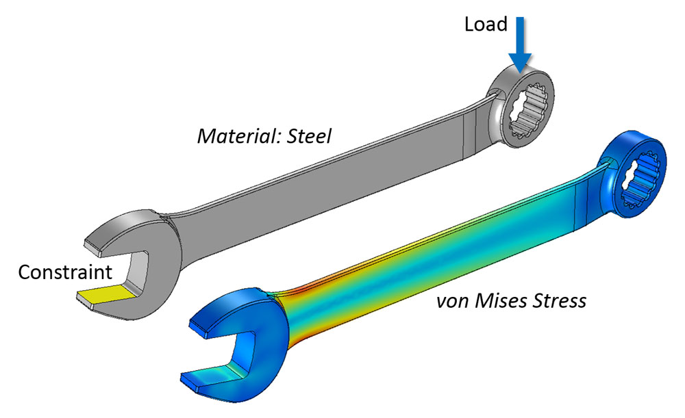 A finite element model of a wrench and the computed stresses. The mesh is not shown.
Once all of this information is assembled into an FEA model, the analyst can begin with a preliminary mesh. Early in the analysis process, it makes sense to start with a mesh that is as coarse as possible – a mesh with very large elements. A coarse mesh will require less computational resources to solve and, while it may give a very inaccurate solution, it can still be used as a rough verification and as a check on the applied loads and constraints.
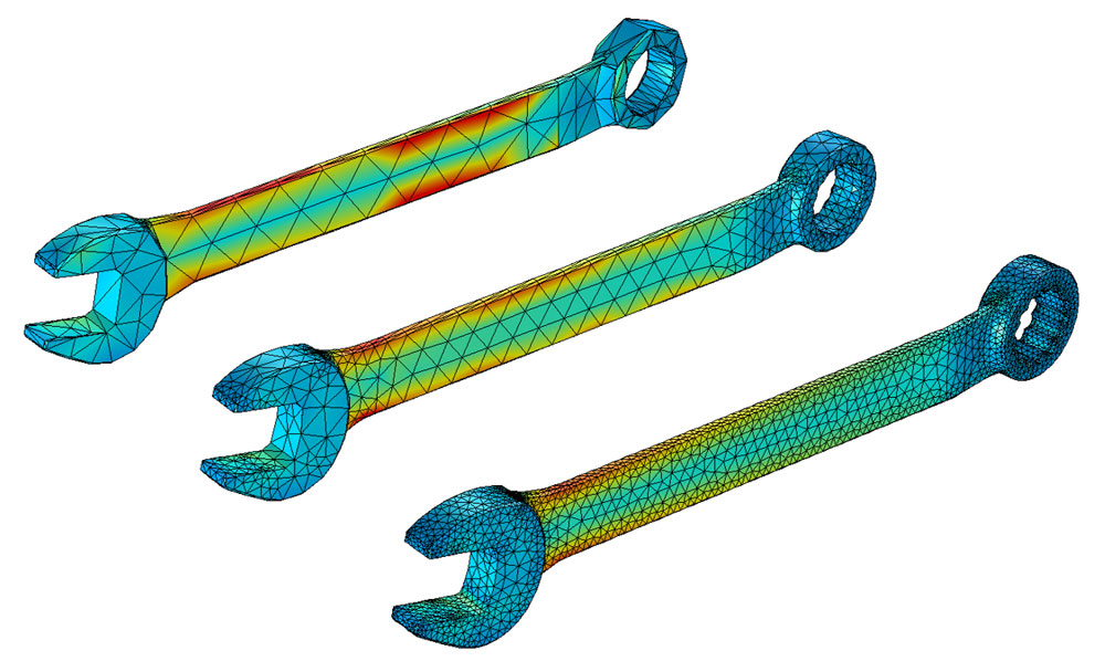 The first few iterations of a mesh refinement study of a wrench, starting with a very coarse mesh.
After computing the solution on the coarse mesh, the process of mesh refinement begins. In its simplest form, mesh refinement is the process of resolving the model with successively finer and finer meshes, comparing the results between these different meshes. This comparison can be done by analyzing the fields at one or more points in the model or by evaluating the integral of a field over some domains or boundaries.
By comparing these scalar quantities, it is possible to judge the convergence of the solution with respect to mesh refinement. After comparing a minimum of three successive solutions, an asymptotic behavior of the solution starts to emerge, and the changes in the solution between meshes become smaller. Eventually, these changes will be small enough that the analyst can consider the model to be converged. This is always a judgment call on the part of the analyst, who knows the uncertainties in the model inputs and the acceptable uncertainty in the results.
Different Mesh Refinement Techniques :
When it comes to mesh refinement, there is a suite of techniques that are commonly used. An experienced user of FEA software should be familiar with each of these techniques and the tradeoffs between them.
Reducing the Element Size
Reducing the element size is the easiest mesh refinement strategy, with element sizes reduced throughout the modeling domains. This approach is attractive due to its simplicity, but the drawback is that there is no preferential mesh refinement in regions where a locally finer mesh may be needed.
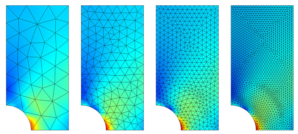 The stresses in a plate with a hole, solved with different element sizes.
Increasing the Element Order
Increasing the element order is advantageous in the sense that no remeshing is needed; the same mesh can be used, but with different element orders. Remeshing can be time consuming for complex 3D geometries or the mesh may come from an external source and cannot be altered. The disadvantage to this technique is that the computational requirements increase faster than with other mesh refinement techniques.
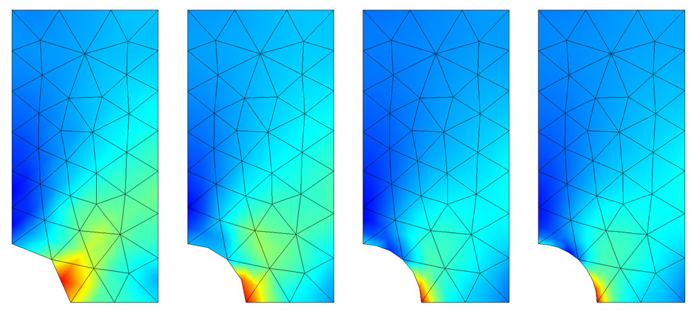 The same finite element mesh, but solved with different element orders.
Global Adaptive Mesh Refinement
Global adaptive mesh refinement uses an error estimation strategy to determine the point in the modeling domain where the local error is largest. The FEA software then takes this error estimation and uses the information to generate an entirely new mesh. Smaller elements are used in regions where the local error is significant, and the local error throughout the model is considered. The advantage here is that the software will do all of the mesh refinement. The drawback is that the user has no control over the mesh. As such, excessive mesh refinement may occur in regions that are of less interest, regions where a larger local error is acceptable.
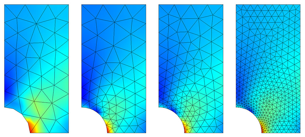 Global adaptive mesh refinement changes the element sizes in a nonuniform manner.
Local Adaptive Mesh Refinement
Local adaptive mesh refinement differs from global adaptive mesh refinement in that the error is evaluated only over some subset of the entire model space, with respect to a specific metric. For example, it is possible to refine the mesh such that stresses at the boundary of a hole are more accurately resolved. This meshing strategy will still remesh the entire model with the objective of reducing the error in one region. If a logical and desirable local metric exists with respect to which mesh can be refined, the local adaptive approach is superior to global adaptive mesh refinement.
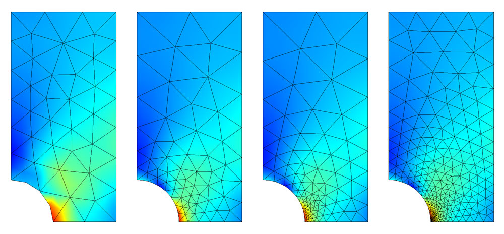 Local adaptive mesh refinement with respect to the stresses at a point.
Manually Adjusting the Mesh
The most labor intensive approach is for the analyst to manually create a series of different finite element meshes based upon the physics of the particular problem and an intuition as to where finer elements may be needed. For 2D models, a combination of triangular and quadrilateral elements can be used. In the case of 3D models, a combination of tetrahedral, hexahedral (also called bricks), triangular prismatic, and pyramidal elements can be used. While triangular and tetrahedral elements can be utilized to mesh any geometry, the quadrilateral, hexahedral, prismatic, and pyramidal elements are helpful when the solution is known to vary gradually along one or more directions. By elongating, or shrinking, elements in certain directions, the mesh can be tuned to the variation in the fields.
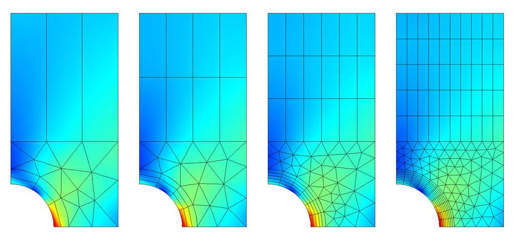 A manually created mesh of a plate with a hole. Varying sizes of triangular and elongated quadrilateral elements are used.
The manual meshing approach requires the most experience and a working understanding of the finite element method and the physics being solved. However, when done correctly, the savings on time and resources can be significant.
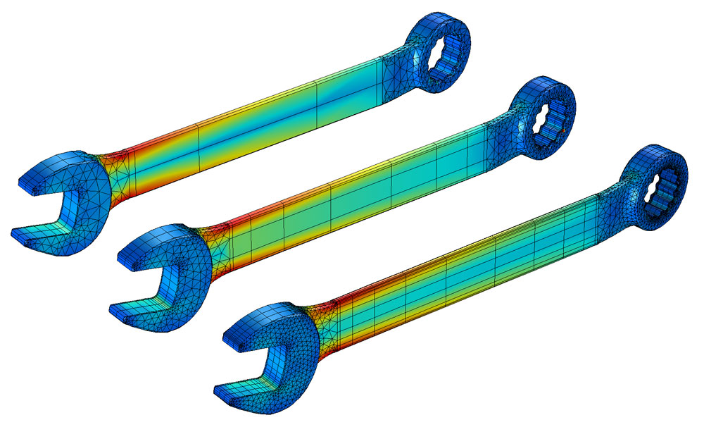 Manual mesh refinement of a wrench using different element types.
Time-Domain and Frequency-Domain Meshing
Along with all of the above techniques, additional considerations should be kept in mind when meshing problems that have time-varying loads. A model with nonlinear material responses or arbitrary time-varying excitations would need to be solved in the time domain. On the other hand, if the applied excitation is of a single frequency or a range of known frequencies and the material properties are linear, then it is preferred for the modeling to take place in the frequency domain. There are additional mesh refinement strategies for each of these cases.
Time-Adaptive Mesh Refinement
Time-adaptive mesh refinement remeshes the model at distinct time intervals and considers an error estimate of the solution at each interval as the metric by which to remesh the model. This is useful when the regions requiring good mesh resolution move over time.
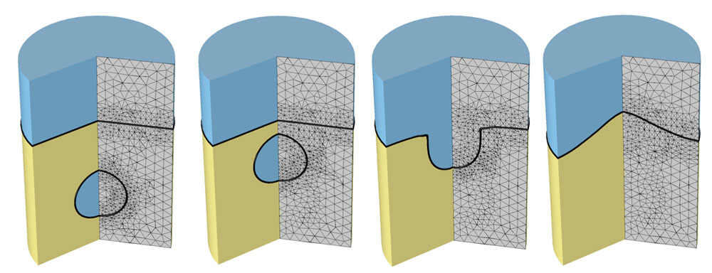 Time-adaptive mesh refinement of a model of a rising bubble solved with a two-phase flow model. The finite element mesh is finer around the phase boundary.
Wavelength-Adaptive Mesh Refinement
When modeling in the frequency domain, both the range of excitation frequencies and the material properties are known ahead of time. Thus, it is possible to predict the wavelength in all modeling domains. The element size must be sufficiently smaller than the wavelength, such that the element polynomial basis functions resolve the waves.
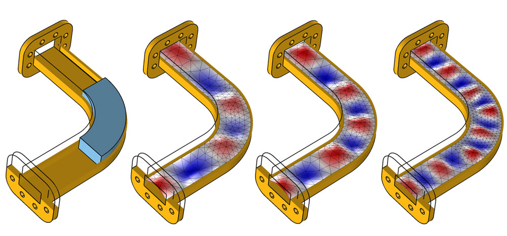 Microwave waveguide with a dielectric load (cutout view). Wavelength adaptive mesh refinement alters the element size based upon the frequency and material properties.
INTODUCTION TO MID SURFACING :
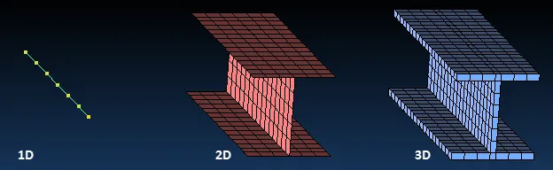
Different dimension elements can be used to represent the same geometry. An I-Beam (W Shape) can be idealized as 1D, 2D, or 3D elements.
Planar elements, also called two-dimensional (2D) elements, are used to represent a structure whose thickness is small compared to its other dimensions. Planar elements can model plates, which are flat, or shells, which have single curvature (e.g., cylinder) or double curvature (e.g., sphere). Planar elements can also be used to model sections that are uniform or non-uniform in thickness.
Midsurface Creation Process
A common way to produce a planar element mesh is to first create midsurface geometry that represent the midplanes of the thin walls and then mesh the midsurface geometry.
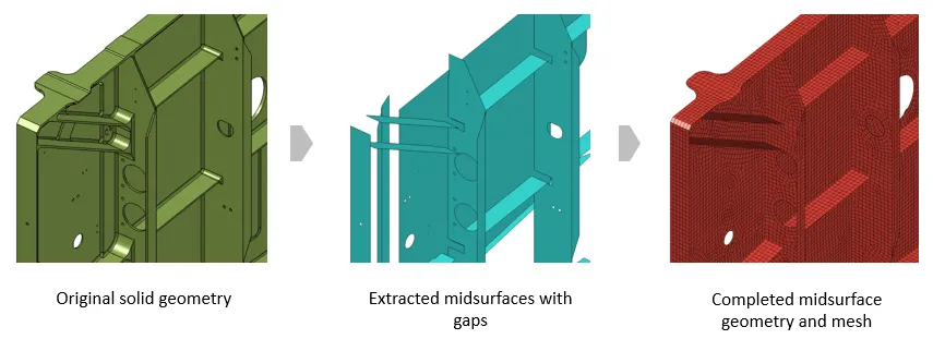
Caption: Midsurface Creation Process
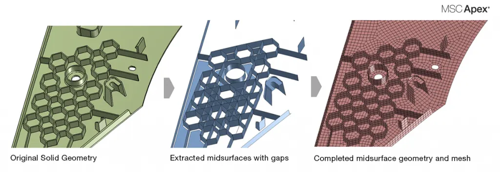
Caption: Midsurface Creation Process for an Automotive Injection Molded Plastic
Procedure :
Step 1: Import the given CAD model to the ansa software and while importing the file model get some glitches to remove those glitches we need to apply topo for entire model and now model looks good.
Step 2: After importing we need to check the geomentry for any geomentrical errors and we have to remove those errors. To remove go to the checks manger and select the geomentry and execute it and it will show some errors we need to fix them.
Step 3: After clearing the geomentry we need to perform a mid surface extraction to the dashboard model, to perform mid surface first we need to measure the entire model and know the model thickness. By measuring the model we can conclude that model has different parts with varying thickness so auto extraction is not possible for the model we nned do it in manual.
Step 4: Now we have measured the entire model to extract manual mid surface go to the offset option and select the faces need to extraction and give offset thickness to extract mid surface. Like this we need to perform manual extraction. For some ribs we can perform direct middle option to create middle surface.
Step 5: Now we have a mid surface and save it seperately by using lock option. Before going to the mesh, again we need to check the mid surfaced model. (same as above step2)
Step 6: After checking geomentry we need to apply the quality criteria and we need to clean topology of geomentry with cut option (like some failing fillets ). Apply the pid for each part.
Step 7: Now go to the mesh deck and start meshing the component step by step with the help of best o[ption or spot mesh option. Here I have used both methods because in some areas these methods give different and fine mesh.
Step 8 : Now mesh has been deployed to the entire model and now we have to clear the quality criteria , here we have performed topology clean up so most the parts did not get any off elemnts but some areas has off elemnts to remove those off elements we use split hybrid option or MV surf or Paste option.
Step 9 : Now we have remove the off elements but we have some rotating trias in the mesh to remove those we use Split, Join, Paste options.
Step 10: Now turn on the 'shell as solid' option whichis in parameter deck, this option makes mid surfaced model into orginial thickness model. Save the file.
RESULTS :
Thus we have created a mid surface and deployed mesh to the car dashboard model by using the ANSA software.
This is the link for the above model : https://drive.google.com/file/d/1w35jv7Eyzq8T5HEJoh3S5P6kZpJP3LEr/view?usp=sharing