Week 12 - Project-1
Objective :
To mesh the car side door model in hypermesh with good quality criteria and mesh flow.
- Import the the geomentry to the hypermesh.
- Extract the midsurface manually for the given model.
- Clean the geomentry manually for the model.
- Mesh the geomentry individually with good mesh flow.
- Check the criteria for the model and reduce failed elements.
- Add the property connectors and add thickness individually and assign them.
Procedure :
Theory :
Why do we carry out the quality check?
Finite Element Method is an approximate Numerical Solutions method for Physical problems. In FEA Results ∝ (directly proprtional) Element Quality. The Good Quality mesh you create, Most Accurate Results you will get. To Acheive the Realiable results & to reduce the Margin of error. We need to create a good quality Mesh. Quality check varies depends on Anlysis and Element type.Some time Hypermesh Creates Zero size Elements while creating a mesh. These elements need to Deleted by checking element Quality. For Non-linear and Crash analysis - minimum Element length Check required.Which is directly influence the Solution time (Time Step Caluclation). Some of the Quality Checks Based on Angles, Shapes, Areas and Element sides.
Aspect ratio: The ratio between longest edge of an element to either its shortest edge or the shortest distance from a corner node to the opposing edge is called Aspect Ratio.
Minimum Length: Hypermesh uses the following three methods to calculate minimum length.
-
The shortest edge (in which the length of the shortest edge of each element is used).
-
The minimal normalized height (which is more accurate, but more complex).
-
The minimal height (which is the same as minimal normalized height but without a scaling factor).
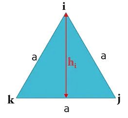
Minimal Normalized Height (MNH):
-
Find the perpendicular distance from each node to its opposite side (hi, hj & hk).
-
Hence, the MNH is minimum of (hi, hj & hk) multiplied by scaling factor [2/√3] (scaling factor ensures that for Equilateral triangle MNH is same as the minimum side length).
Aspect Ratio Calculation for Quadrilateral Element:
Aspect ratio: The ratio between longest edge of an element to either its shortest edge or the shortest distance from a corner node to the opposing edge is called Aspect Ratio.

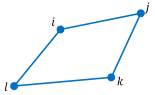
Minimum Length: Hypermesh uses the following methods to calculate minimum length.
-
The shortest edge (in which the length of the shortest edge of each element is used).
-
The minimal normalized height (which is more accurate, but more complex).
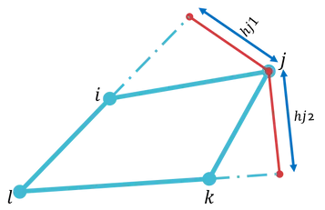
Minimal normalized height (MNH):
-
For each corner node, draw perpendicular line to the other two sides which are not containing that node.
-
With respect to the figure, from node “j” draw perpendicular lines to sides “lj & lk” as shown. Measure the lengths “hj1 & hj2”.
-
Similarly, Repeat the above procedure for all other nodes (I, k & l) and find out their lengths (total 8 Lengths).
-
Thus, Minimal normalized height (MNH) is taken to be the minimum of all eight lines and the four edge lengths (thus, the minimum of 12 possible lengths).

Example: Aspect Ratio of a rectangle:
-
MNH = Min.Edge length=5
-
Aspect Ratio=10/5 = 2

Skew Angle
An angle is formed by the two lines which pass through the midpoints of the sides of the quadrilateral. The skew angle represents the absolute value of the difference between the angle and 90 degree. A rectangle has the skew angle of 0 since the formed angle between lines is 90 degree. For the triangle and quadrilateral elements, the skew angle is found as shown in the figure. For solid element (Tetra, Hexa, Wedge), it calculates the skew angle for each element faces and assigns with the minimum value.
Taper
It checks for the amount of deviation of the quadrilateral element from a rectangular shape. A rectangular element has the taper of 1, and it gets away from the rectangular shape (closer to the triangular shape), the taper becomes smaller. For the quadrilateral elements, the skew angle is found as shown in the figure. For solid element (Hexa, Wedge), it calculates the skew angle for each element faces and assigns with the minimum value.
Warpage
The warpage of the quadrilateral elements is defined as the deviation from a best-fit plane that contains the element. It is not always a case to define a plane with 4 nodes. Therefore, a node of the quadrilateral element may be formed outside of a plane. The warpage is a measurement how this node has been deviated, and as it gets closer to 0, the element become more planar. For the quadrilateral elements, the warpage is found as shown in the figure. For solid element (Hexa, Wedge), it calculates the warpage for each element faces and assigns with the maximum value.
Steps to follow :
Step 1 : Import the given cad model to the hypermesh using the import option.
Step 2 : After importing check the geomentry for any free edges and surface glitches and try to remove them using the quick edit options.
Step 3 : Now create the midsurace for given model manually using surface edit option. Here we are going for manual because surface consists of variable thickness if we do auto midsurface hypermesh will create extra mid surface which we don't need.
Step 4 : After extracting midsurcface we have to clean the geomentry using the quick edit option like toogle edge. Here we are cleaning geomentry because there are some areas where meshed elements will fail.
Step 5 : Now we have to mesh the midsurfaces so go to 2d mesh and select the automesh and give 4mm and select the surfaces which you want mesh , here i have performed individual mesh for good mesh flow and less tria concentration.
Step 6 : After meshing the surface create criteria table with given values.
Step 7 : Now check the quality criteria for meshed surfaces and reduce the failed elements using drag tria, node optimization e.t.c repeat the process until the failed elements reduce to zero.
Step 8 : Now we have to attach some rib surfaces to the main surface so we use replace option for that operation.
Step 9 : Now add individual connector and create property connectors individually and add thickness and assign property connector to main connector.
Step 10 : To check thickness is added or not, go to 2d detailed element option.
Result :
Thus I have performed mesh on car side door model by creating midsurface manually and with good quality criteria.
Here I am attaching my files with the google drive link :https://drive.google.com/file/d/1WIr8xN38CIlWK8efdMYXMqZi638HFMev/view?usp=sharing