Assignment 5-RADIOSS Interfaces & Study of Effect of Notches Challenge
Objective :
To mesh the bumper model and to simulate and extract the results of crash tube test using hyper mesh, hyperview and hyper graph. Here six types of crash tube tests are performed by using different contact types and different positions of notches.
Theory :
In this assignment we learn two types of contacts 1. Type 7 and 2. Type 11
What is Interface/Contact modeling ?
Normally the explicit analysis method solves highly complex nonlinear problems and contact
definition is an important part of many nonlinear problems. In order to get the best results and
real behavior of any simulations, including contacts, accurate modeling of contact interfaces
between bodies is a crucial part. Based on the applications RADIOSS has a large number of
contact types. Each of those interfaces was developed for a specific application field, but this
field is not the only choice criteria. In RADIOSS an interface is created by defining the master
segment and slave set. The master segment can be parts, elements, contact surface, node sets
and similarly for slave the selection can be parts and node sets. Once these master slave sets
are identified the algorithm will check these locations for potential penetration of a slave node
through a master segment, and this check is done in every time step.
• TYPE7, variable stiffness, node to surface contact
• TYPE11, variable stiffness, edge to edge contact
The Penalty Method Used In Interfaces:
The penalty method treats the behavior between slave nodes and master segments as springs
that generate resistive forces as a function of penetration. Spring elements are created between the slave node and its projection. The spring stiffness is automatically computed according to the material and property of both master segment and slave node.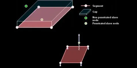
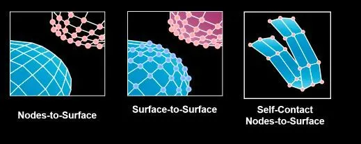
Interface Type 7: Nodes to Surface Contact
• Automatic node to surface contact interface using penalty method with variable stiffness
• A gap is defined around the master segment and the slave nodes
• The contact gap can be constant or variable
• Resistive forces are applied to keep slave nodes out of the contact gap
• Interface time step is computed to insure stability
Interface type 7 is a general purpose interface and can simulate all types of impact between a
set of nodes and a master surface. Contrary
to interface types 3 and 5, interface type 7 is
non-oriented and slave nodes can belong to
the master surface. Therefore, this interface
can simulate auto-impact, especially buckling
during a high speed crash. Interface type 7
solves all problems and limitations
encountered with interface types 3 and 5. The 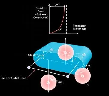
search for the closest segment is done via a
direct search algorithm; therefore, there are
no search limitations and all possible contacts
are found. The energy jumps induced by a
node impacting from the shell edges are
removed by the use of a cylindrical
gap around the edges.
Finally, the main advantage of
interface type 7 is that the stiffness
is not constant and increases with
the penetration preventing the node
from going through the shell midsurface. This solves many bad contact
treatments (common when using
either interface type 3 or 5).
The gap used in interface type 7 is
rather different than those of the
previous interfaces. The gap used is
on both sides of the shell mid-surface,
and a cylindrical gap is added around
the edges.
Important Interface Parameters
Igap: Determines how the size of the gap is calculated
Gapmin Minimum gap for activation of interface
Inacti: Action to take if initial penetrations exist
Istf :Affects how the stiffness of the interface is calculated
Iform: Friction formulation
Stmin: Minimum stiffness to use in the interface
Idel: What to do with slave nodes and master segments if element fails (deleted) that they
are attached to.
Interface Type 7: What About Initial Intersections?
• Intersections result if slave nodes are past the master segment (shells or solids)
• This condition can cause locking situations leading to computation failure
• If slave nodes lie on the master segment an ERROR will occur because of the Type 7
contact stiffness definition
• Initial intersections should be removed from the model (using HyperMesh or
HyperCrash).
• Penetrations result if a slave node is closer to the master segment than the calculated gap
• Initial repulsion forces give an error in the energy balance due to the interfaces work
• There are options in the solver to remove initial penetrations
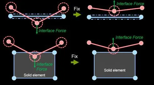
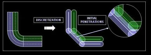
Interface Type 11: Edge To Edge Contact
In the case of edges crossing, Type 11 interface can be added to capture the physics correctly
• Type 11 is defined by identifying master and slave lines (edges)
• Type 11 works similar to Type 7 in terms of:
• Penalty formulation
• Gap definition
• Search method
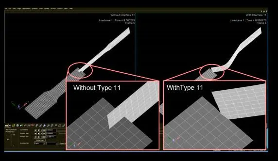
A General Remark About Master & Slave:
The coarser the mesh, the stiffer the structure will be provided the material and structural
properties are same. Hence, the Master is typically meshed coarser so that the Slave does not
penetrate into master. That is why we choose less deformable or high stiffer structure as master
and less stiff as slave.
Procedure :
1. Import the bumper model to hyper mesh and start to clean the geomentry which has free edges. To remove this free edge either use surface trim or after mesh we can use spot weld option. Here I have used both option so I can explore the both options.
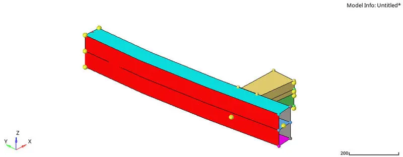
2. Now trim the middle part of the bumper to do that go surface edit > trim with surface plane > intersecting surface plane and select the surface plane to trim and middle surface is attached to bumper part.
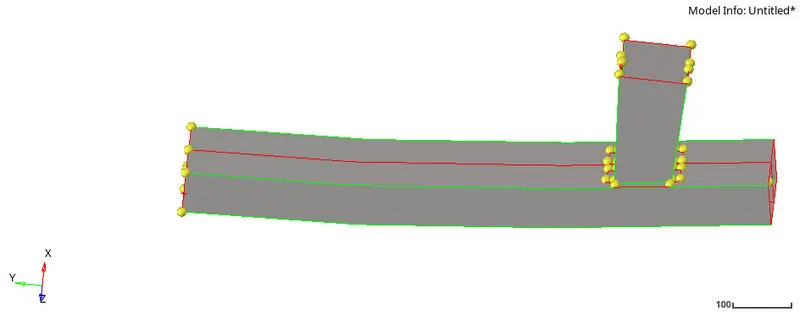

3. Now mesh the complete part with 6mm mesh size and after meshing go to 1d element and use connector spot weld option to create spots on the part.
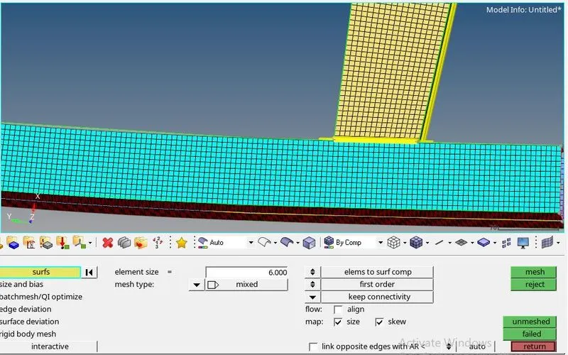

4. After that use reflect option to get another part of bumper on y-axis, because this part is not full part by creating like this now it is full bumper part.

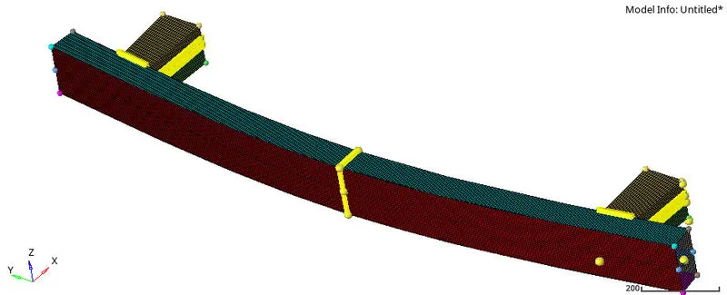
5. Now simulate six different types of crash test using radioss solver and extract the results using hyperview and hypergrapgh.
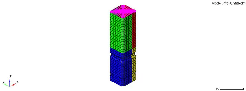
Case 1: Import the .rad file to the hyper mesh and after importing all cards are available to the model and create th part for all case which is shown below. Solve the model using radioss. Results of case 1 is discussed at ending.
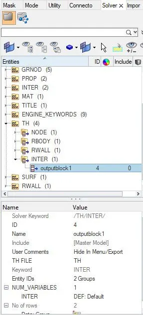
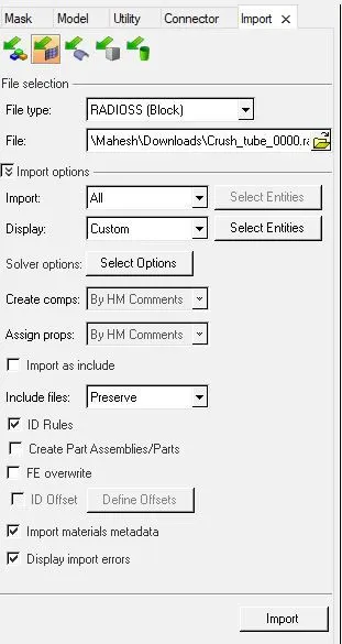
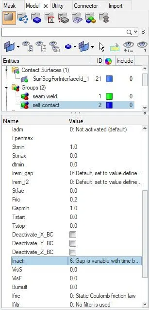
Case 2: For this case open the group card and self contact card and change the inacti to 6, by doing this there wiil be no intial penetration in the model and gap is reduced and scaled and gives good accuracy.
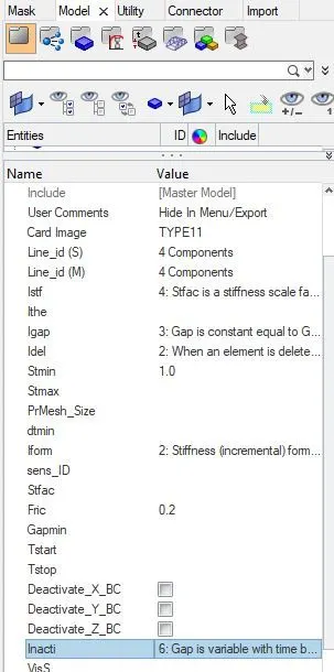
Case 3: For this change the contact type to type 11 and give master and slave components as all parts and solve the model.
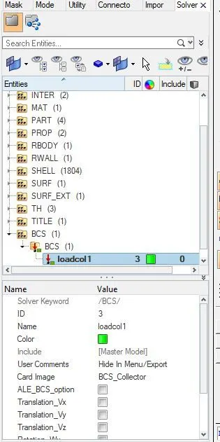
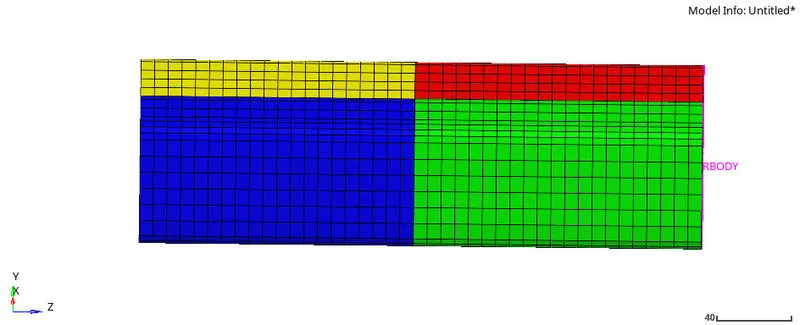
Case 4. For this remove all the notches in the model and delete the boundary condition card which is in solver deck and solve the model by keeping remaining cards as it is.. Notches are removed using align nodes.

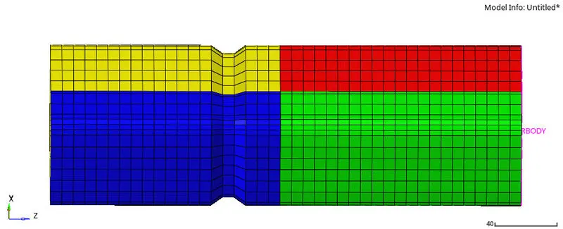
Case 5: For this create notches at middle of the model and solve the model. Same as case4.
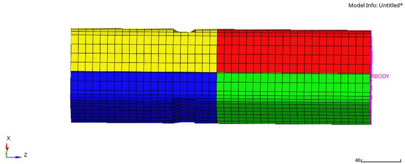
Case 6: For this create middle left and right side of the model and solve the model. Same as case4.
Results&Discussion :
1. After solving the all six cases open the .out files and check whether there is error in solving or not and tabulated all cases total time, no .of cycles, time consumed and mass error.
| No | Time consumed | No.of Cycles | Error% | Mass error% |
| Case1 | 541.06 | 83600 | -3.8% | 0.0 |
| Case2 | 483.50 | 83600 | -3.8% | 0.0 |
| Case3 | 1067.8 | 104100 | -7.5% | 0.0 |
| Case4 | 396.57 | 77800 | -3.0% | 0.0 |
| Case5 | 417.40 | 81000 | -2.9% | 0.0 |
| Case6 | 435.23 | 81800 | -3.7% | 0.0 |
2. Now all six different type crash tubes are accepted, so switch hypermesh to hyperview and open the .h3d files of all six cases individually.
Case 1: Import .h3d file of case1 and extract the results of displacements, contact forces and vonmises stress.

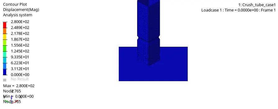
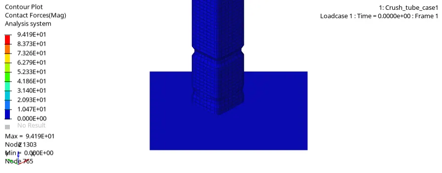
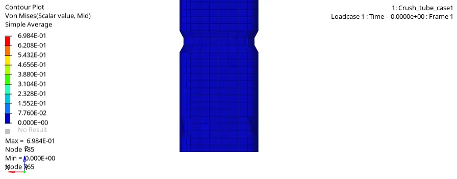
From all three simulations we can see that two notches in front and middle of the model is slowing down the model or stopping the model when the model crashes into the rigidwall. Since we used type 7 contact the physical representation is accurate because we can see contact forces when ever the shell elements get into touch some forces are created which can be seen in the contact force simulation.
Case 2 : Extract the results for case2 .rad file Where we used inacti as 6.
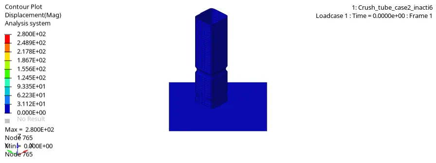
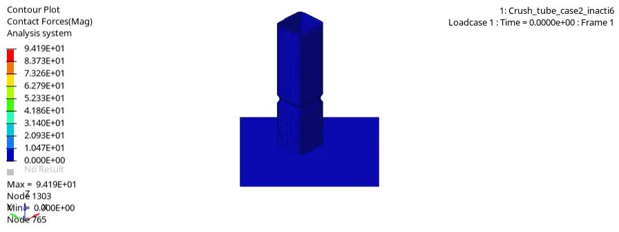
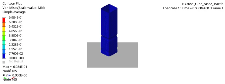
By defining the inacti as 6 alone makes the model to prevent from intiall penetrations which is not occured in the model, so due to this reason alone both case 1 and case 2 has same results.
Case 3: Now extract the results for type 11 contact results.
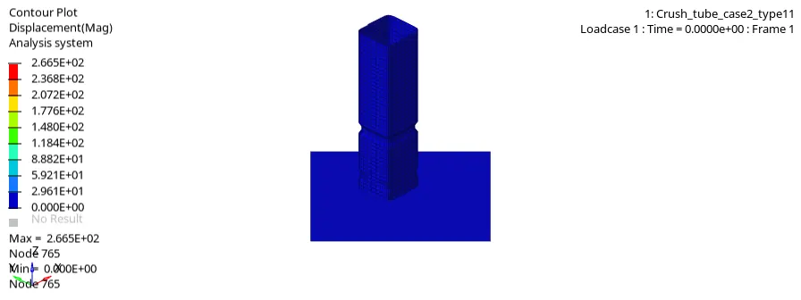
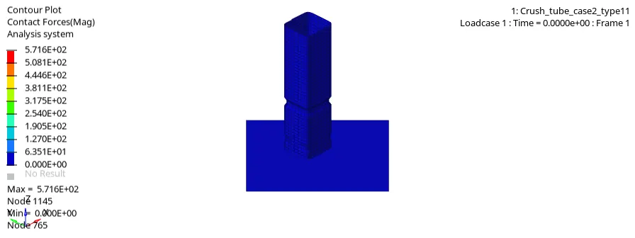
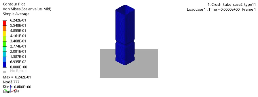
From the results we can see that it almost act as case1 and case 2 because it has penalty methods, but the contact forces are increased when model crashes into the rigidwall this is due to the type 11 stops penetrating into another part and more contact is occured for slave part.
Case 4: Now extract the results of case 4 which has no notches and no boundary condition.
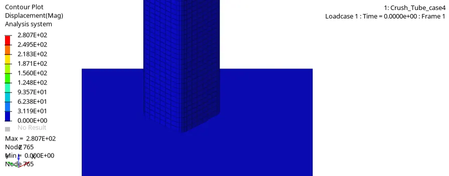
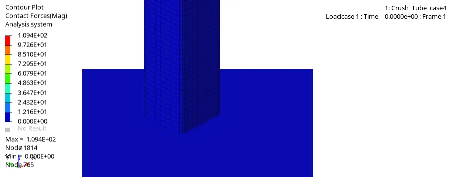
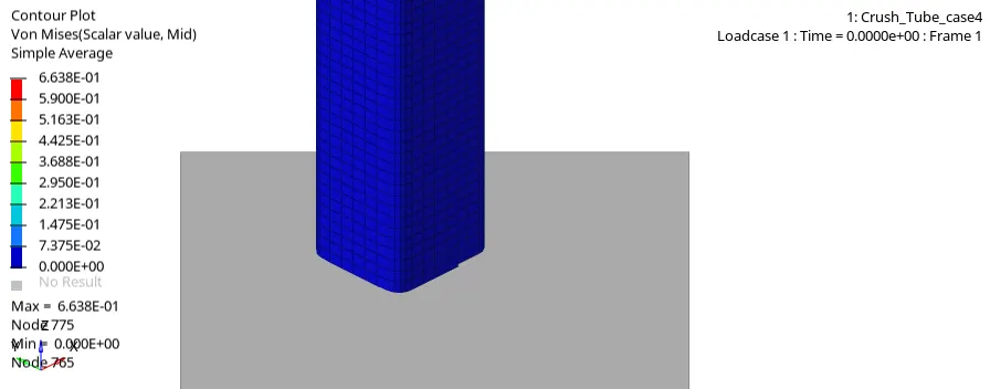
From results we can see that more displacement in the model, this is due to no notches in the model and we can see decrease in the contact forces and stress which is also a same reason.
Case 5: Now extract the results of case 5 which has notches at the middle of the model.
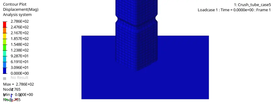
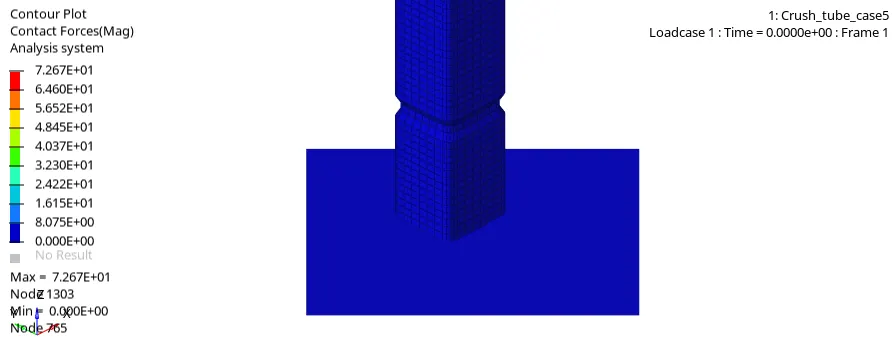
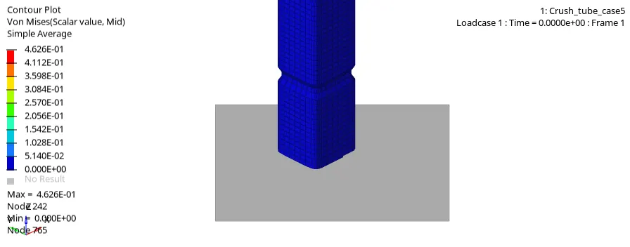
From the results we can see that displacement is reduced when compare to the case4 this is due to notch created at the middle and contact forces also reduced in the model but stress is increased at the middle notch.
Case 6: Now extract the final case where the model has two opposite notches at the midddle and conditions are same.
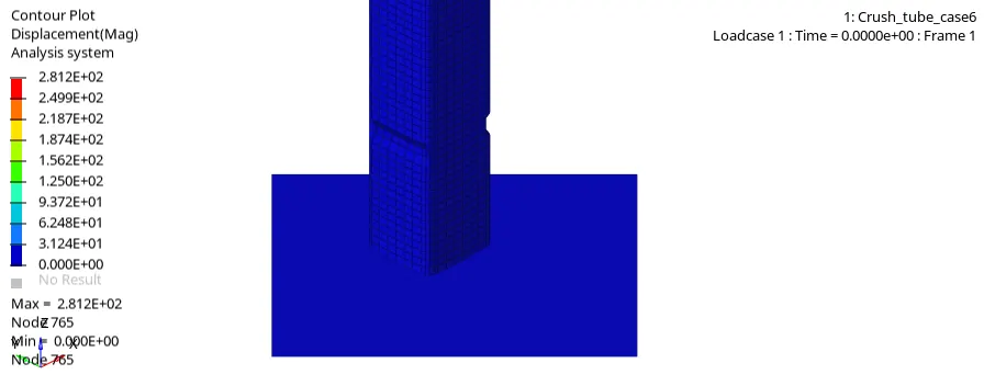
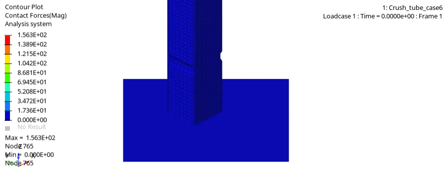
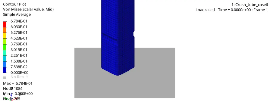
For this model we can see that there is increase in displacement of the model, notches are reason for to crash the model to the rigidwall. Stress also increased in this model compared to case5 model this is because of side notches.
3. After extracting all simulation results now switch the hyperview to hypergraph and extract all six cases plots.
Case 1: Using hypergraaph 2d import .To1 file of each cases here import first case file and select the x and y variables as shown below for all the cases.

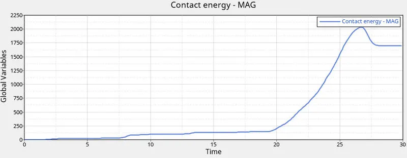
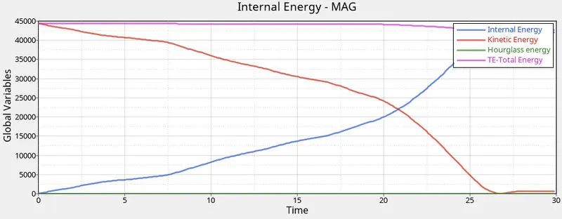
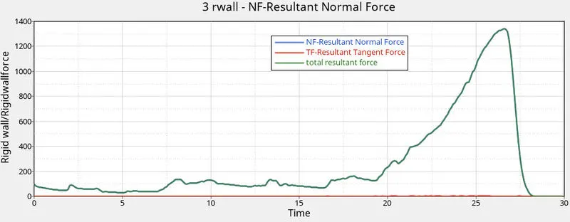
From all three plots we can see that variation of the plot occurs at after 20 ms which is after crashing. There is very less hourglass energy and normal contact energy in the model so the solver gives less energy disipation. Contact forces are increased after the crash.
Case 2: Now extract the results for inacti 6 case.
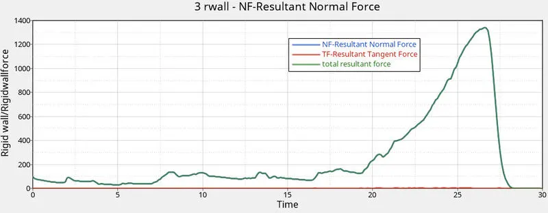
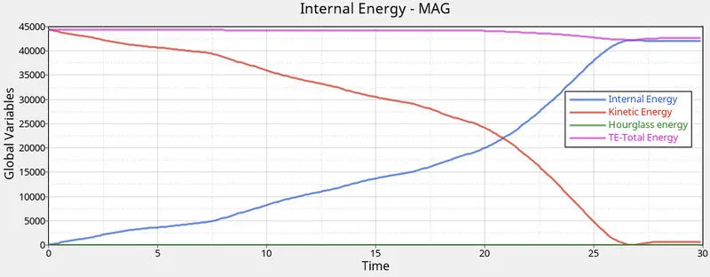
This case excatly looks like case 1 because even we have given this model to solve as no intial penetrations the model does not have intial penetrations at first so it gives same results.
Case 3: Now extract the results for type 11 case.
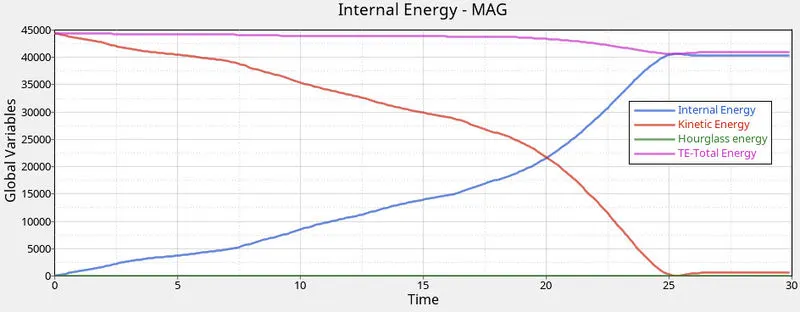
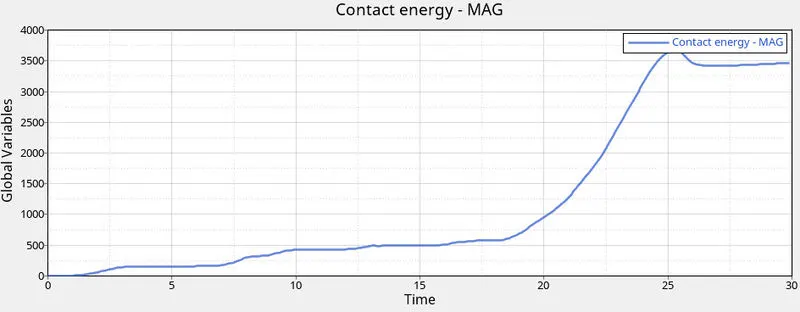
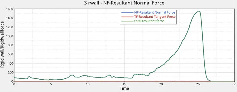
From the plot we can see there is more disipation of contact energy and due to this reason we have faced more disipation of energy in the solver and there is increase in the contact forces, so type 11 model creates more contact forces and energies compared to the case 1 and case 2.
Case 4: Now extract the results of no notch model.
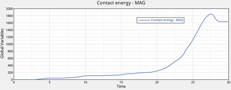
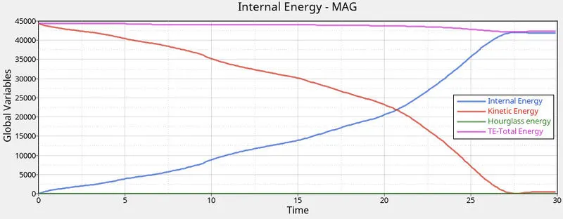
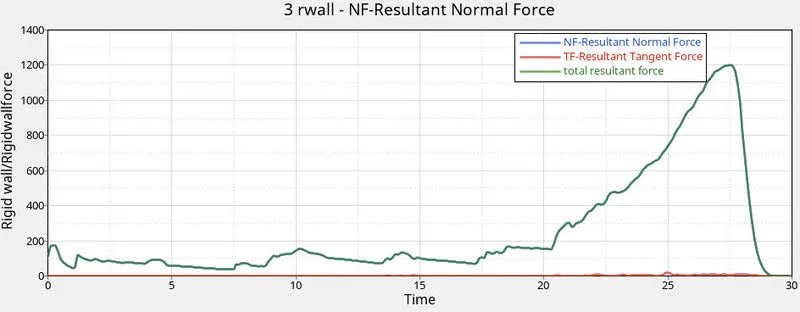
Due to no notches in the model there is less disipiation of energy and solver runs the model quickly but the energy transfered to entire model is also quick.
Case 5: Now extract the results of middle notch case.
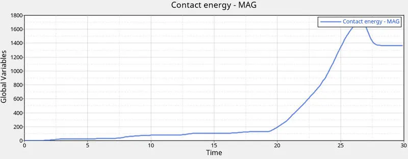
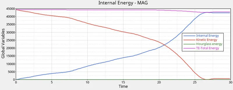
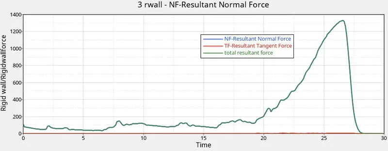
This is same as case 4 but more contact energy is created in this model.
Case 6: Now extract the opposite notches of model.
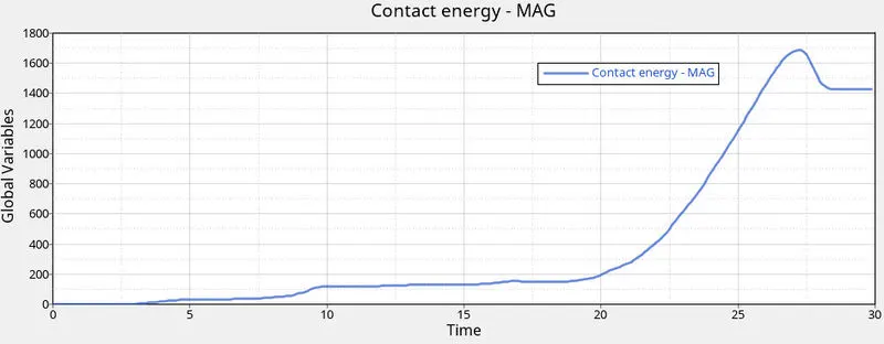
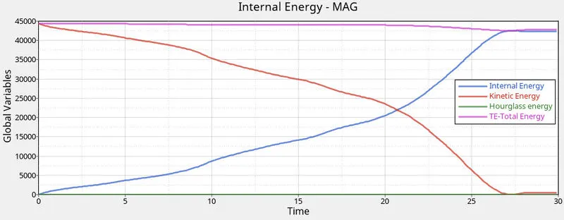
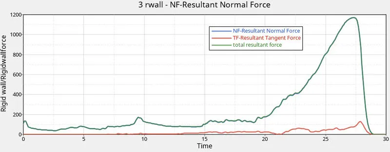
From this we can see extra force is generated due to the notches and energy plot is same as case 5.
Conclusion :
Thus meshing is performed to the bumper model and also peformed spot weld connections in required places. After solving all six cases and extarcting all results we can conclude that type 7 connection works perfectly and by activating inact 6 it even clears the intial penetrations even though this model does not have any, where type 11 connection works perfect but dissipates more contact energy which leads to the solver error for bigger models. Coming to notches, these are the main reason for absorbing the energy and displacing lately to crash entire model, due to this reason alone many automotive industries creates extra fillests, reinforcements to the BIW parts which aborbs more energy and crashes slowly which gives time to open the airbags.