Project 2
Objective :
To create a mesh for a car suspension assembly model and also give connections for model using the ANSA software.
I. Import the model into the ANSA software.
II. Check for geomentric errors and clear them.
III. Create mid surface for required parts.
IV. Mesh the suspension assembly parts seperately with given criteria.
V. Create a volume mesh for the tria meshed parts.
VI. Connect the parts using the NASTRAN deck or with the connection manager.
Theory :
Suspension is the system of tires, tire air, springs, shock absorbers and linkages that connects a vehicle to its wheels and allows relative motion between the two. Suspension systems must support both road holding/handling and ride quality, which are at odds with each other. The tuning of suspensions involves finding the right compromise. It is important for the suspension to keep the road wheel in contact with the road surface as much as possible, because all the road or ground forces acting on the vehicle do so through the contact patches of the tires. The suspension also protects the vehicle itself and any cargo or luggage from damage and wear. The design of front and rear suspension of a car may be different.
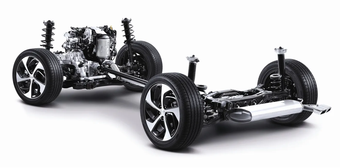
A coil spring was used to support
either the upper or the lower arm to provide dampening. Shock absorbers began
to be used to dampen shock loads and also to provide resistance to spring
oscillations. Later it was learned by shortening the upper arm; wheel tilt (camber)
could be controlled to prevent edge loading tires while cornering. The power
transmitting drive axle in the rear served as the beam‐type suspension with
dampening provided by either leaf or coil springs as well as shock absorbers.
When front‐engine front‐drive passenger cars were introduced, the upper arm
was rotated up and replaced by a member called a “strut” which contained the
concentrically mounted spring and shock. This arrangement provided additional
space for transverse mounted engine/transmission modules and the front drive
shaft. This same type of suspension was also used in the rear of many cars. Trucks
continue to be front‐engine, rear‐drive vehicles many of which are using beam‐
type axle suspension systems in both the front and rear.
Types of Suspension Components
There are three basic types of suspension components: linkages, springs, and
shock absorbers. The linkages are the bars and brackets that support the wheels,
springs and shock absorbers. Springs cushion the vehicle by dampening shock
loads from bumps and holes in the road. Shock absorbers use hydraulic pistons
and cylinders to cushion also the vehicle from shock loads. They also serve to
dampen spring oscillations, thus bring the vehicle back to a neutral position soon
after being shock loaded by a road obstruction.
Links: There are a number of various shaped links that are used for the different
types of suspension systems. They vary from straight bars to forged, cast or
stamped metal shapes that best fit to support the springs, shocks and wheels
onto vehicle frames or body structures. The simplest linkage is a straight bar that
connects one wheel to the other on the opposite side of the vehicle. Others can
be intricately shaped to connect springs, shock absorbers and wheels to vehicles
as explained later.
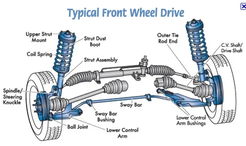
Springs : There are three different spring types that are used in suspension
systems: coil, leaf and torsion bar. Coil springs are merely wound torsion bars.
They are commonly used because they are compact, easily mounted and have
excellent endurance life properties. Leaf springs are long thin members that are
loaded in bending. They are used as an assembly being comprised of several
layers of thin metal to obtain the correct spring rate. Leaf springs serve as both
the damping member and the linkage. Torsion bars rely on the twist of a long bar
to provide a spring rate to dampen car shock loading. Torsion bars mount across
the bottom portion of a vehicle and are more difficult to package than others.
Shock Absorbers: Shock absorbers use a piston and cylinder along with adjustable
valves to control the flow of hydraulic fluid to set the damping force in both the
retract (jounce) and extend (rebound) positions. Shock absorbers are set to
retract under a lower force than to extend. This action absorbs road bump forces
and dampens spring oscillations resulting in better vehicle ride and control.
Suspension System Terms
• Camber : Looking directly at the front of the vehicle, camber refers to the
tilt in (+) or out (‐) of the bottom half of the tire.
• Caster : Looking directly at the side of the vehicle, caster refers to the tilt
rearward (+) of the bottom half of the tire.
• Toe : Looking directly at the top of the vehicle, toe refers to the slant in (+)
or out (‐) of the front half of the tire.
• Jounce : Jounce refers to the bounce or vertical movement of the vehicle
suspension upward when it contacts a bump in the road.
• Rebound : Rebound refers to the movement of the vehicle suspension in
the opposite direction of jounce.
• Shimmy : Shimmy is an uncontrollable oscillation of the steering system
experienced by two opposing wheels.
• Knuckle : The knuckle is the suspension component that incorporates the
spindle or hub that the wheel bearings and wheels mount on.
• King Pin : The king pin is the vertical component in the knuckle that the
wheels turn on when the vehicle is steered.
• Spindle : The spindle is the long tapered bar‐shaped piece that is fitted to
the knuckle on which the wheel bearings and wheels are mounted.
• Hub : The hub is the hollow part of the knuckle that replaces the spindle in
mounting the bearings that support the wheel.
• Ball Joint : A ball joint is a fastener or connector that allows movement in all
directions.
• Tie Rod : A tie rod is a component that firmly connects one wheel of a
vehicle to the wheel on the opposite end to provide steering.
• Track Bar : A track bar is a rod that connects a suspension beam to the
frame to give lateral support.
• Unsprung Weight : Unsprung weight is the total weight of all components in
a vehicle that are not dampened by the springs and shocks like the wheels
and other closely associated equipment.
• Scrub : Scrub is the lateral movement of a tire against the pavement due to
suspension system camber changes during jounce and rebound.
Types of Suspension Systems
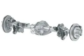
Beam Axle : Initially, the front axle of rear‐drive automotive vehicles was of a solid
beam design. It consisted solely of a fixed continuous member extending across
the entire front end of the vehicle connecting the two steerable wheels. This is
referred to as a “dependent” suspension system as the two wheels are
mechanically linked together as opposed to an “independent” suspension system
where the two wheels are not directly linked together. The original Model T
passenger cars were rear‐drive and had a dependent front suspension system
whereby a solid beam axle extended across the entire width of the vehicle
connecting the two wheels. The axle was of forged I‐beam steel construction and
had ends machined to allow the assembly of vertically mounted kingpins enabling
the wheels to rotate to provide for vehicle steering. To dampen the ride, a
transverse mounted semi‐elliptical inverted leaf spring was installed between the
axle and the car body. The two downward curved ends of the leaf spring were
fastened to each end of the axle while the higher center section was fastened in
two closely spaced locations directly to the car frame.
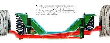
Dual‐Beam Suspension : Dual‐beam front suspension is popular with one U.S.
auto manufacturer for light trucks. Dual beam suspensions are
considered “independent” suspension systems as the two wheels are not directly
connected as they are on the solid beam suspension discussed above. The major
advantage of dual‐beam suspension is that front shock loads from pavement
anomalies are isolated to the side where they are encountered. This is opposed to
one‐piece front beam suspensions where shock loads encountered on one wheel
are transported all the way across the vehicle causing excessive body shock
loading and passenger discomfort. The disadvantage of dual‐beam front
suspensions is that the wheel camber changes with vehicle vertical movement
causing tire edge wear and wheel scrubbing. The dual suspension arms of the dual
beam system used by the U.S. automaker for light trucks overlap each other and
are as long as the design allows minimizing the above mentioned disadvantages.
Suspension Comparison :
• Beam Axle : This is a type of suspension that is a strong, sturdy and
maintains good tire contact with the road under all load conditions. It is a
“dependent” type meaning the wheels are mechanical connected such that
when one hits an obstruction on the road, it is felt across the entire width
of the vehicle. This suspension is good for trucks.
• Dual Beam Axle : This is a strong, sturdy suspension that does not maintain
as good contact with the road as the beam axle suspension. It is an
“independent” type of suspension meaning that the wheels are not
mechanical connected such that when one hits an obstruction on the road,
it is not felt across the entire width of the vehicle. It is used on light truck
front.
• Double Wishbone : This is a lighter, more costly suspension than the beam
type but adds more room for packaging other components. It is an
independent type of suspension that keeps good tire contact with the road
under full suspension travel. Camber, caster, and toe can be closely
controlled. Good for passenger cars.
• Short/Long Arm : This type of suspension is similar to the double wishbone
except that the upper arm is made shorter than the lower arm. This design
feature maintains good tire contact with the road under all cornering
conditions. It is good for performance vehicles.
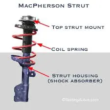
• MacPherson Strut : This type of suspension is similar to the double
wishbone except that the upper arm is rotated up and replaced with a long
member called the “strut”. The strut incorporates the spring and shock in a
concentric package and attaches to mounts high on the vehicle. This design
adds more room for packaging front engine/transmission modules and
adjoining drive shafts.
What is volume mesh ?
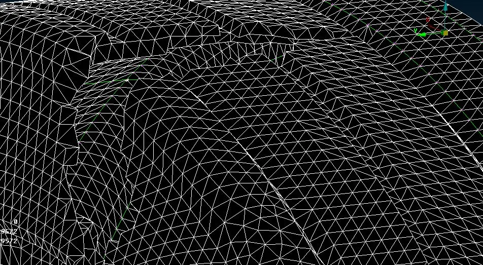
Volumetric meshes are a polygonal representation of the interior volume of an object. Unlike polygon mesh, which represent only the surface as polygons, volumetric meshes also discretize the interior structure of the object.
Process of Volume mesh :
A tetrahedral mesh is created by two steps: first, generating a triangular mesh of
the boundary of the target volume, then filling the inside of the triangular mesh with
tetrahedral elements. A surface mesh may include two types of defects, geometric
defects and topological defects. A self intersection is one of the common geometric
defects, and a common topological defect is a gap or a hole located where the mesh
needs to be closed. Due to complexity of molecular structure, the surface mesh is
often of poor quality, even has defects. This makes it difficult to get high-quality
tetrahedral mesh. In this chapter, we have built a tool chain to generate high-quality
biomolecule mesh by combining a number of mesh generation tools. TMSmesh is
first used to generate the molecular surface triangular mesh. The mesh quality is
then improved through topology check and smoothing. Finally, the volume mesh is
generated using TetGen.
What is FE connector ?
Most structures involve some form of jointing or connection. Using rivets to connect structural plates is almost as old as the introduction of bronze and then iron into early civilization. Bolted connections became possible with the advent of screw cutting methods and usage was accelerated by the standardization of pitch and thread, for example. Even today, fabricated structures such as aircraft and ships use many thousands of bolts and rivets to connect components together. Other large-scale connection technologies include welding and spot welding. The improvement of adhesive technology coupled with much wider use of composites has meant a major resurgence in the use of bonding.
Connections can be of a continuous nature, such as in large surface regions of plates, flanges and where other abutments exist. Alternatively, discrete load paths may be formed by lugs and pins, clips or similar connectors.
The engineer is faced with a difficult decision when attempting to simulate such connections and joints within a finite element analysis (FEA). In many cases the details of each individual connection can be ignored if an overall stiffness or strength assessment is to be made and the connection is assumed reasonably continuous. However there may be doubts about the local flexibility and load paths developed with this assumption. It may be that the assessment of local behavior of the connector is essential to a safety case, for example with main attachment fittings. In some cases the interaction between the connectors and the surrounding structure is critical, as in the case of pre-loaded bolts and inter-rivet buckling.
What is rb2 and rb3 elements ?
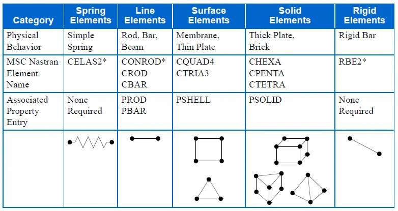
The Nastran group of elements often described as the "Rigid elements" are very useful
engineering analysis tools. "Rigid Element" is a slight misnomer, but the term is still used to
describe the most commonly used items: the "RBE2" and the "RBE3".
A rigid element is a link from one node to one or more other nodes, where the motion of the
node(s) is governed by the "degrees of freedom" you choose to connect. A rigid element is
actually a constraint equation rather than an actual element, but for practical purposes that
matters little, except for the tips to avoid common errors with rigid elements
What is the difference between RBE2 and RBE3 elements ?
Both elements "look" the same, in that they have a single node connected to one or (usually)
multiple other nodes. The difference is that the RBE2 element adds (infinite) stiffness to the
structure, while RBE3 elements "distribute forces" around the connected nodes, without adding
any stiffness.
A rigid element can be as simple as two nodes connected at coincident locations (although it
would be very unusual to use an RBE3 in that configuration), through to the more common
appearance of a "spider" or "sea urchin" connection, or any arbitrary connection of one to
multiple nodes.
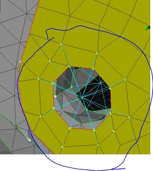
RBE2 Rigid element used to approximate the effect of a bolt head / washer.
For an RBE2 rigid element, the single node is the "independent node". It has 6 degrees of
freedom, regardless of what your FEA graphical interface looks like. The other node(s) you select
are the dependent nodes. You decide which of their degrees of freedom you wish to connect.
Note that it is important to understand the significance of your choices.
Procedure :
Step 1: Import the model to the ANSA software and now we can see the entire modelbut while importing it creates some geomentrical errors we have clear them.
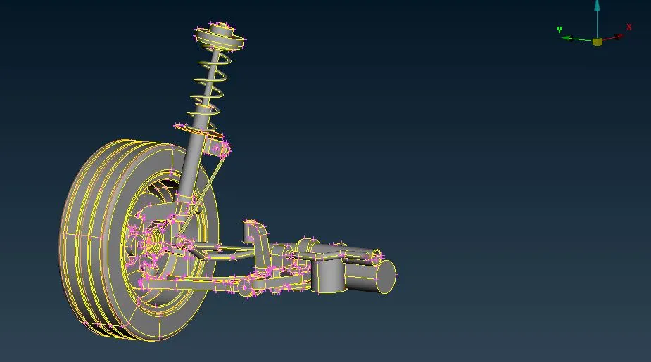
Step 2: To clear geomentric errors we use checks manager for that, here we are not going to perform check geomentry for entire model at once we are going to do seperately for each part of car suspension assembly.
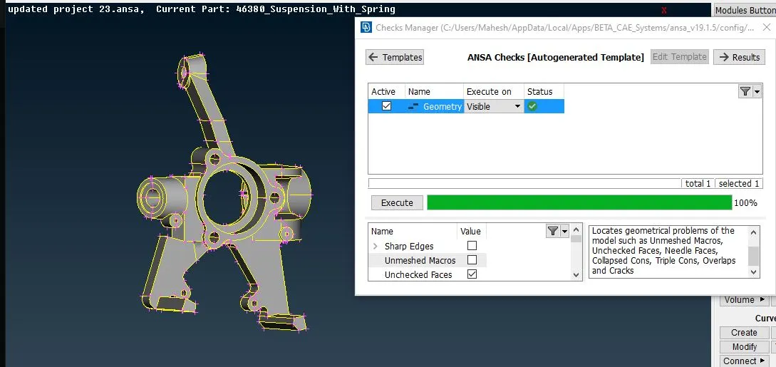
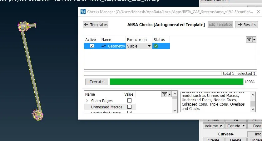
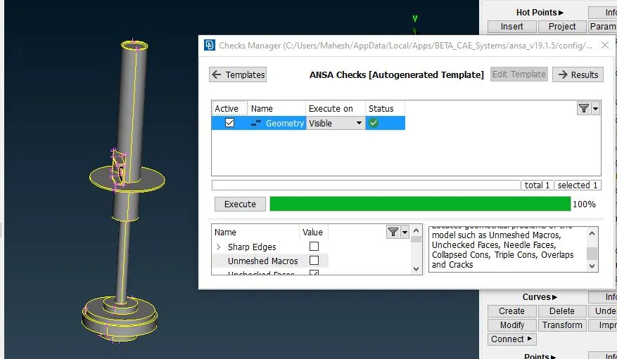
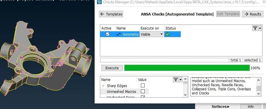
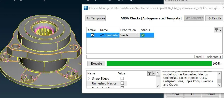
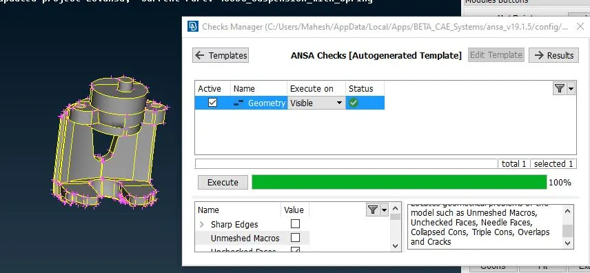
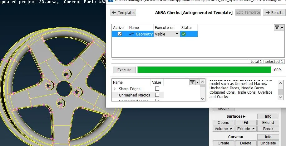
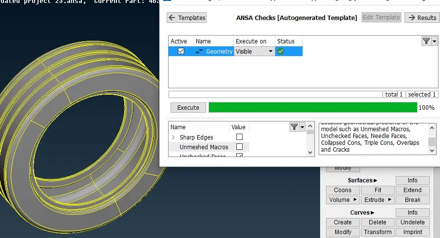
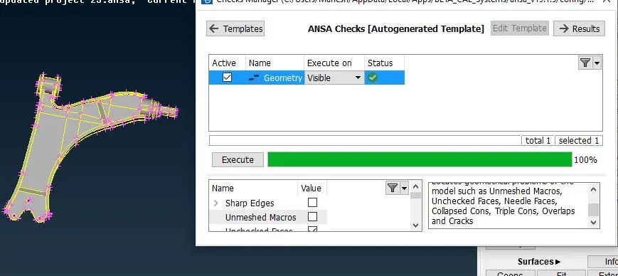
Step 3: After cleaning the errors now we need to measure the entire geomentry for which part has to be mid surfaced and which has to be volume mesh.
Step 4: Now we know that wishbone part and spring lower insulator are less than 6mm so we need to extract mid surface for them and then go for the mesh. To extract mid surface first we need to seperate the parts and store them in lock manager. Now we can perform mid surface using the offset option.
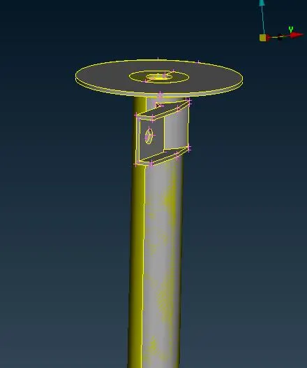
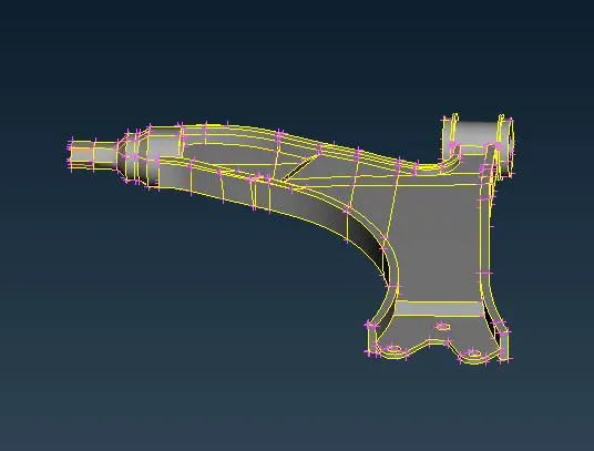
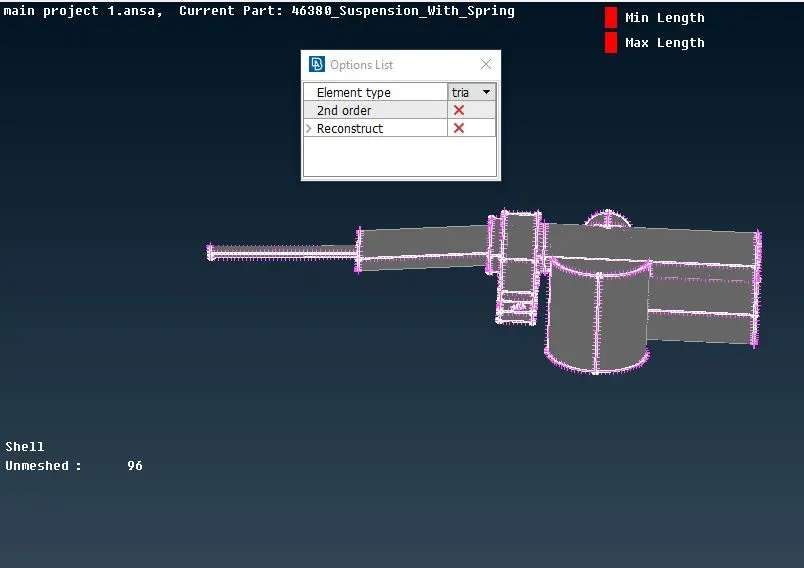
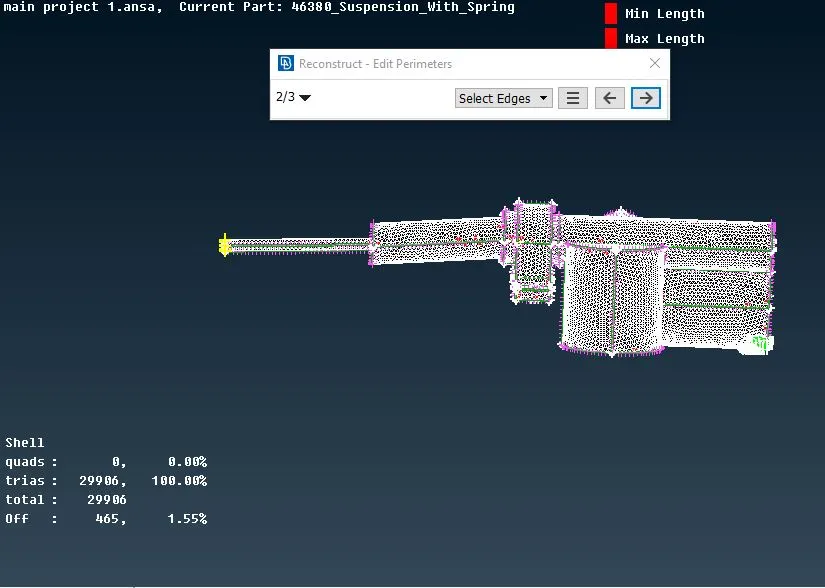
Step 5: After extracting the mid surface here we can perform mesh for these parts before that perform toggling( 'cut' ) for the parts because some area will fail for criteria and create off elements. Now give quality criteria for these parts and go to mesh deck and selcect the spot mesh and select the part. For clearing off elements reconstruction option is enough.
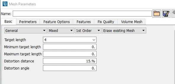
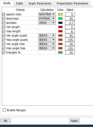
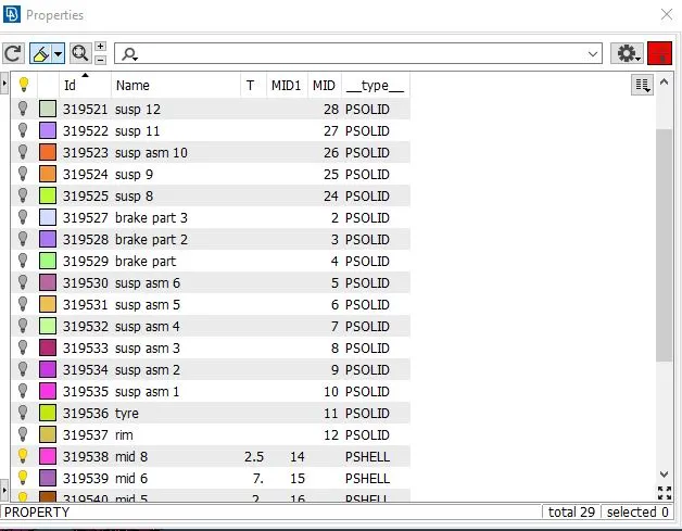
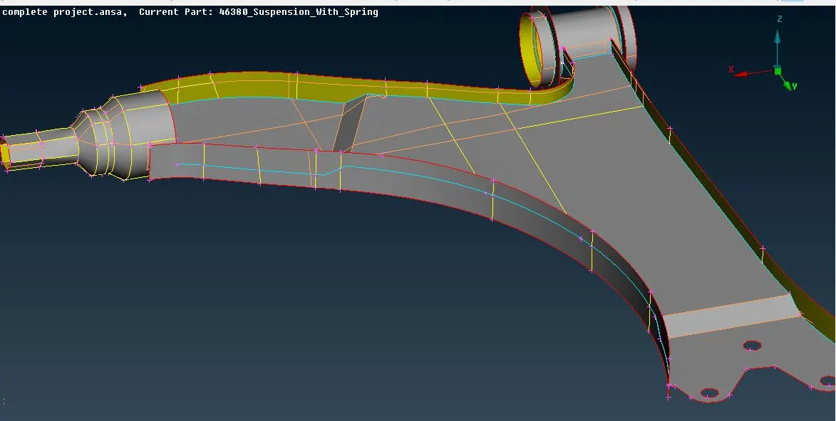
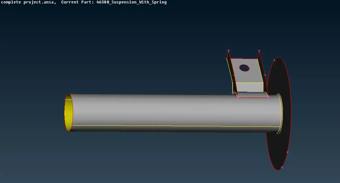
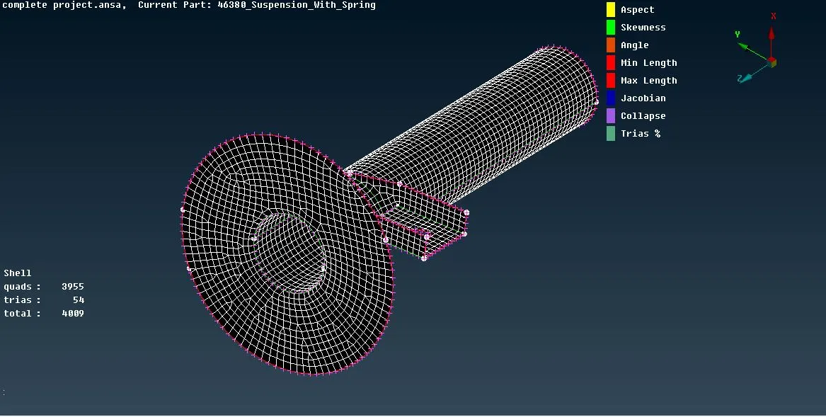
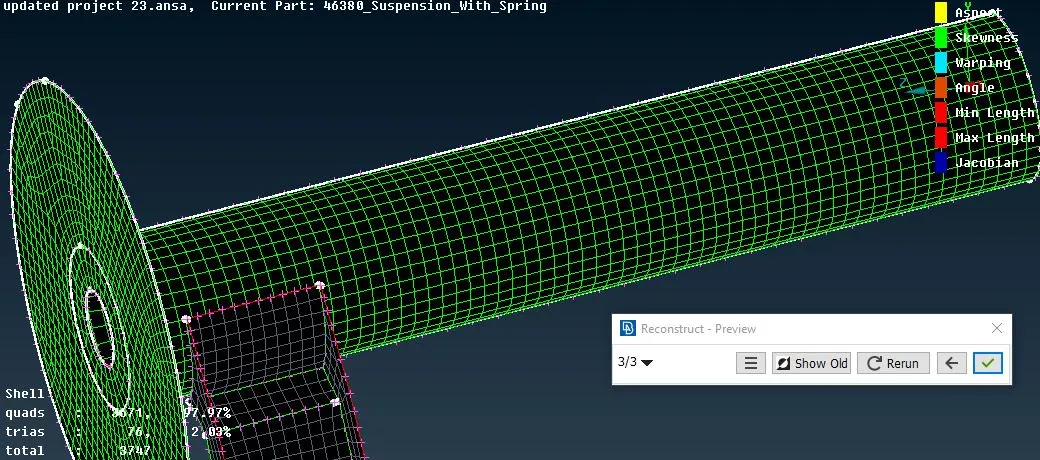
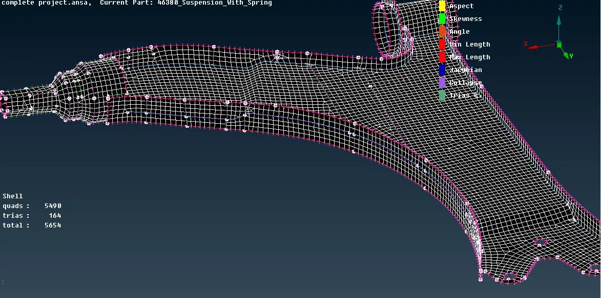
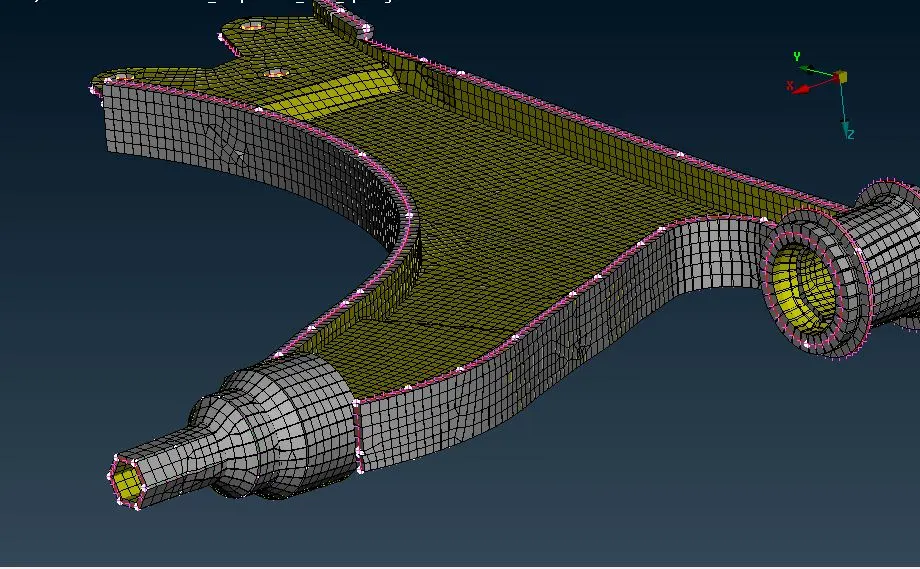
Step 6: Now we have to perform mesh for remaining parts which are seperated, here we are meshing rim part and tyre part because these two has to mesh with ortho tria and quality criteria is same for the both.
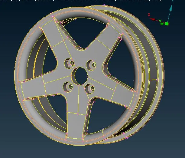
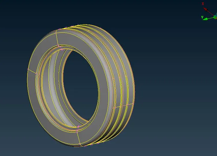
Step 7: First give quality criteria for the parts and selct the ortho tria option and go to the mesh, before meshing we need to perform the toggling and defeaturing for these parts because we know that mesh will create a lot of off elements. After meshing is completed with ortho tria we need to fill entire part with tetra elements.
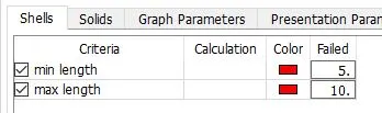
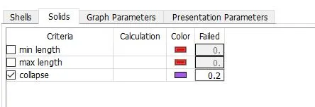
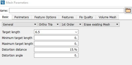
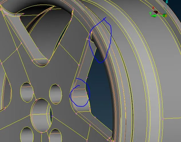
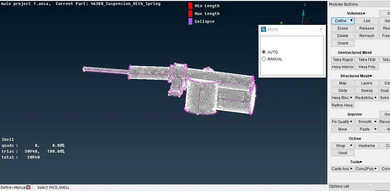
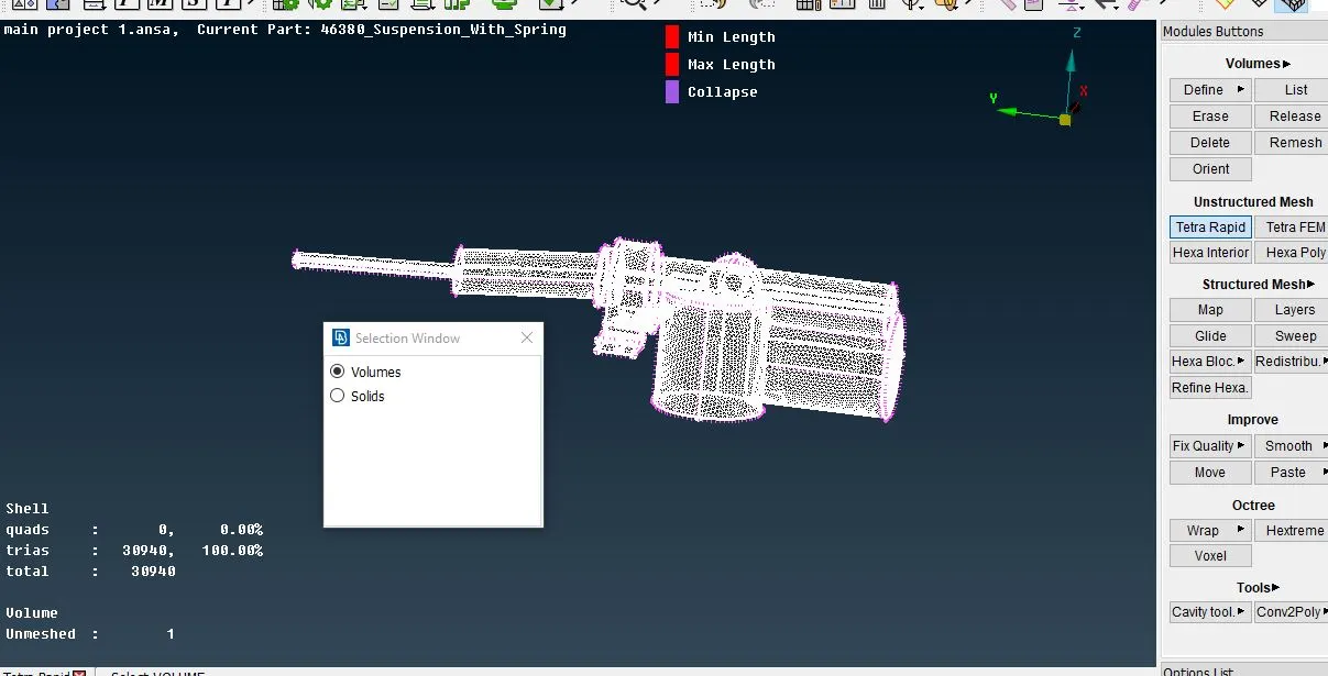
Step 8: Now we have to fill trias for these parts to do that we will use the volume mesh option. First we need to create volume for these parts and define a pid for the volume and then we need to select the option which fills the tetras in the volume i.e, tetra rapid or tetra fem.
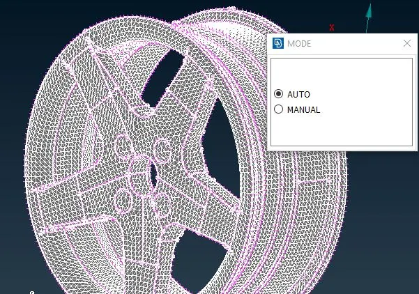
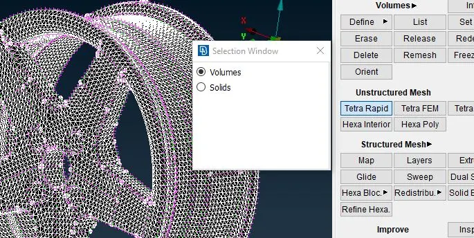
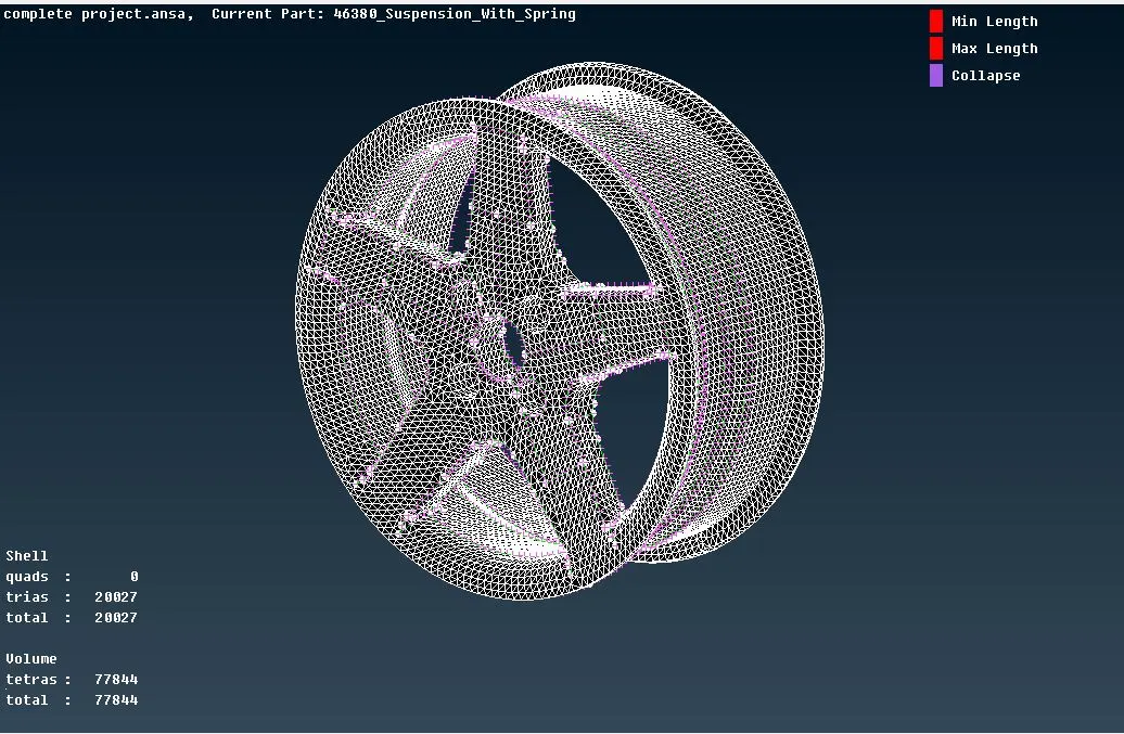
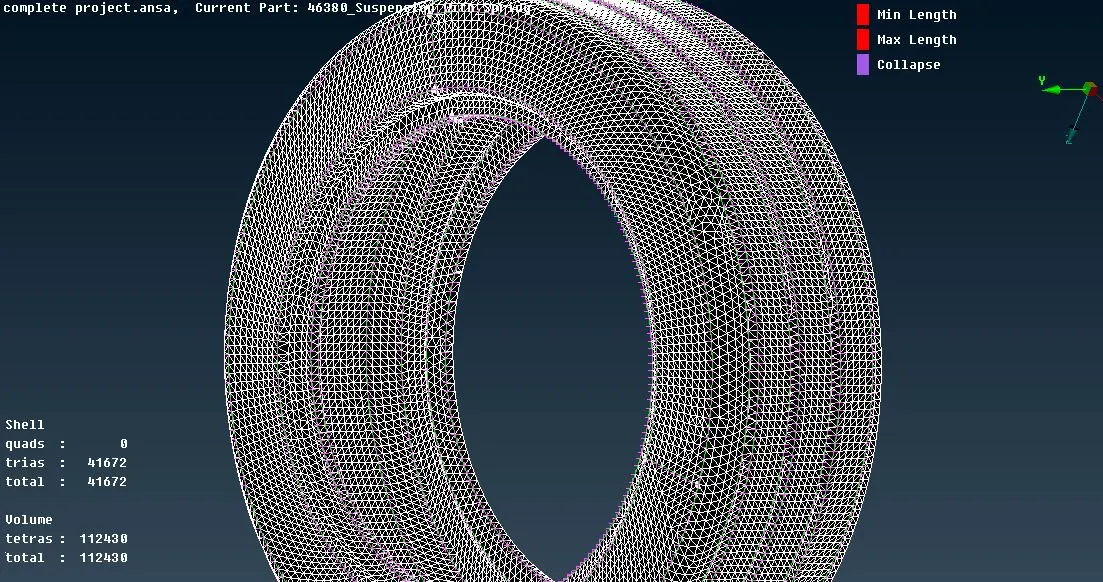
Step 9: Now we need to perform mesh for remaining parts with same quality criteria and perform volume mesh for all the parts. Here steps are same as above parts like rim and tyre but quality is changed.
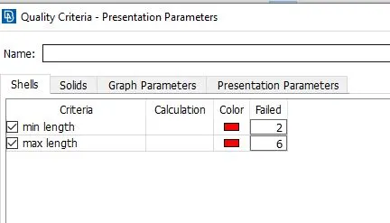
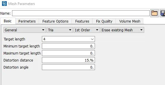
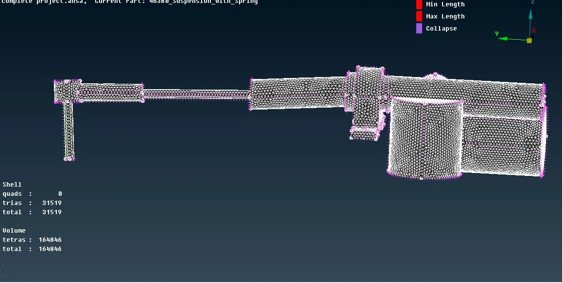
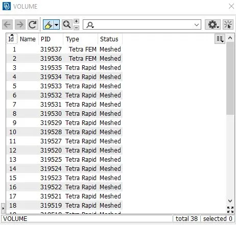
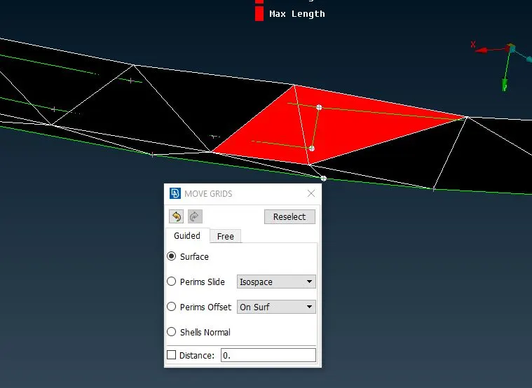
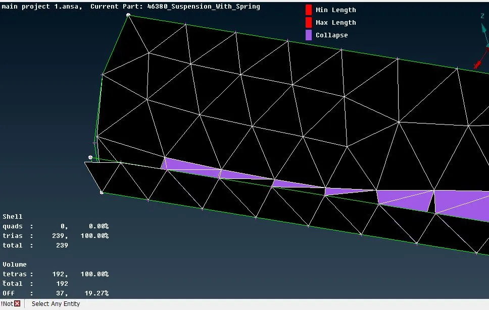
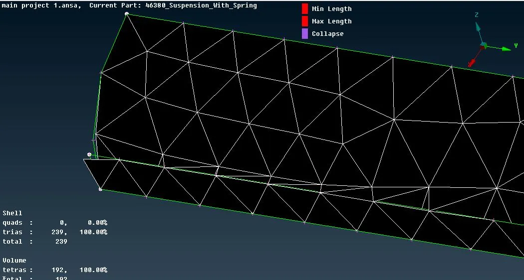
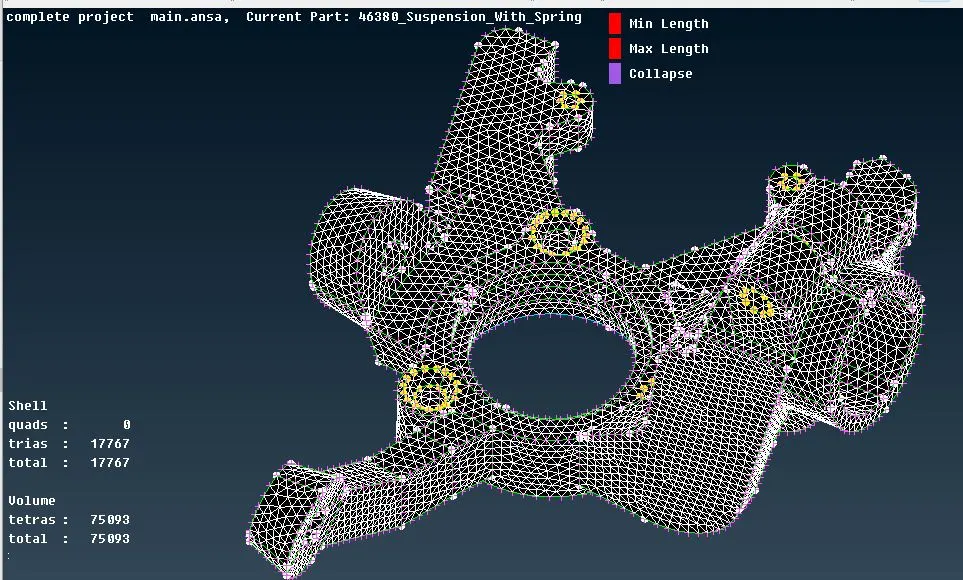
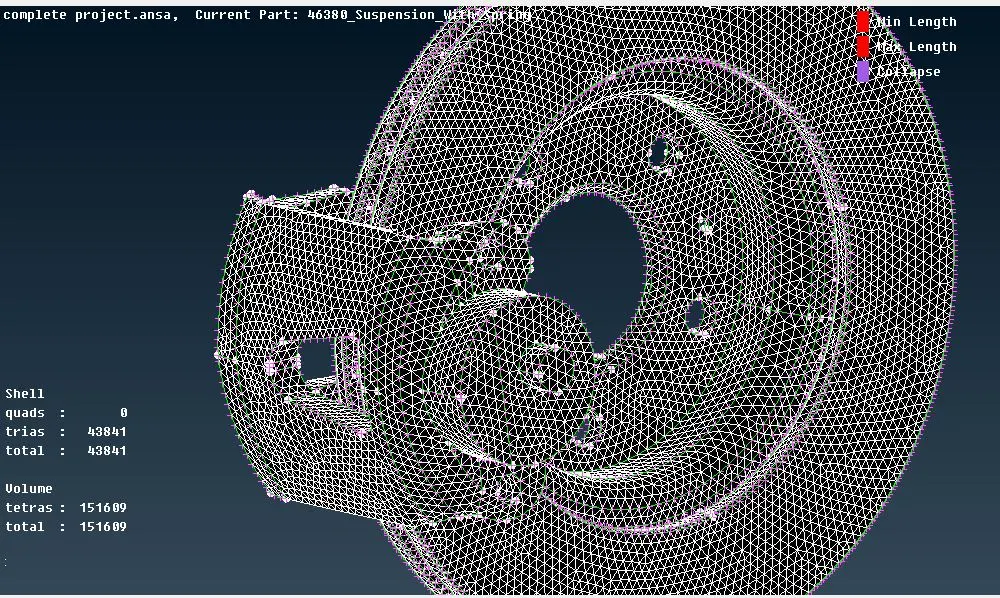
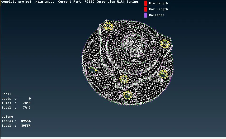
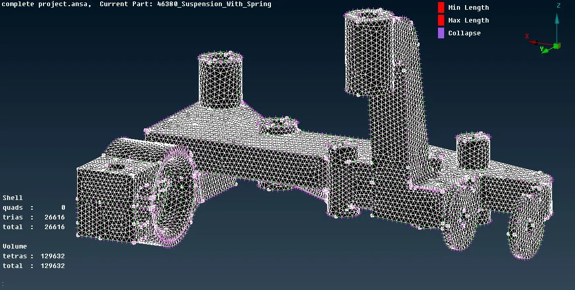
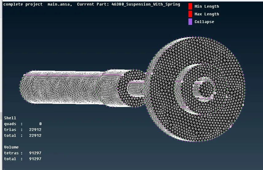
Step 10: Now we need to bring all meshed parts to one place using the option lock manager.
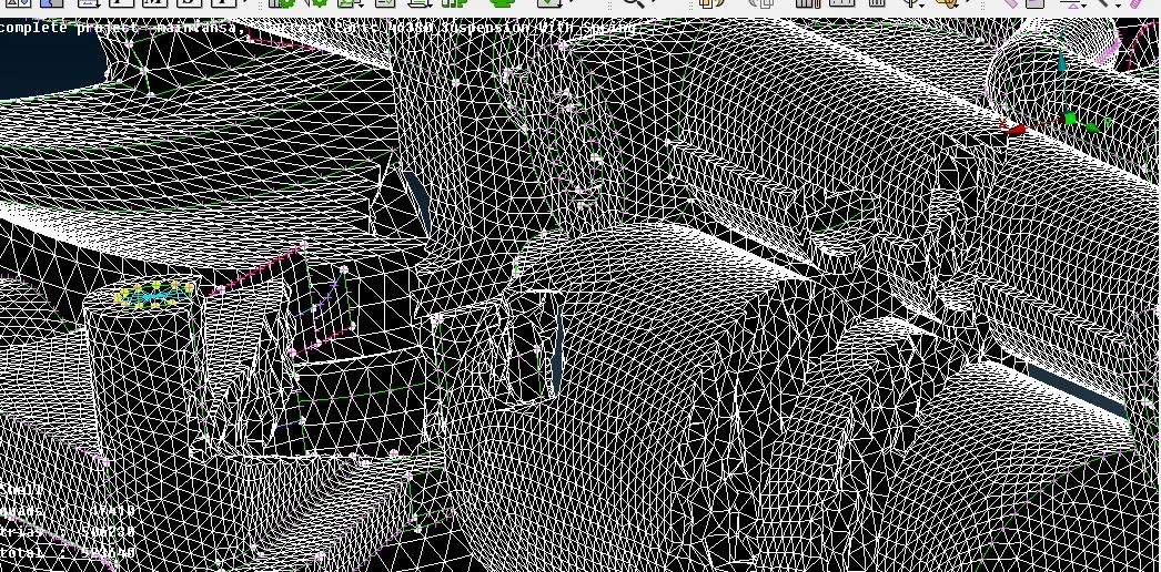
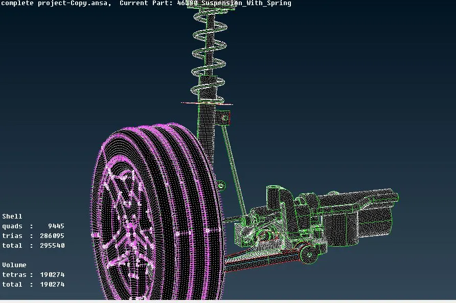
Step 11: After that we need to mesh the spring in order to do that first we need to create a miid curve for the spring and with the help of that we can mesh that using the Cbar option with given element size as 4mm.
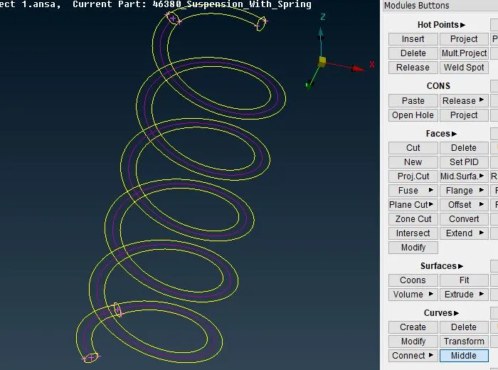
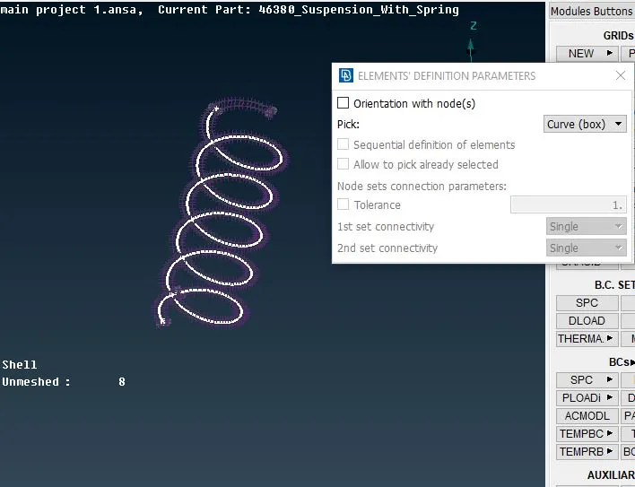
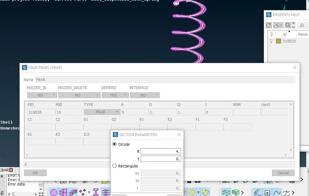
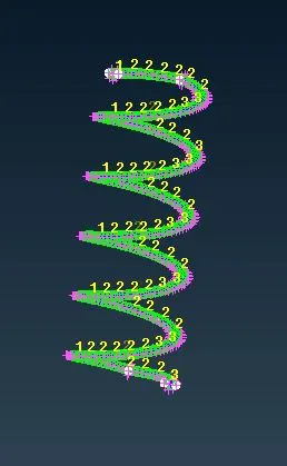
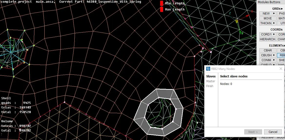
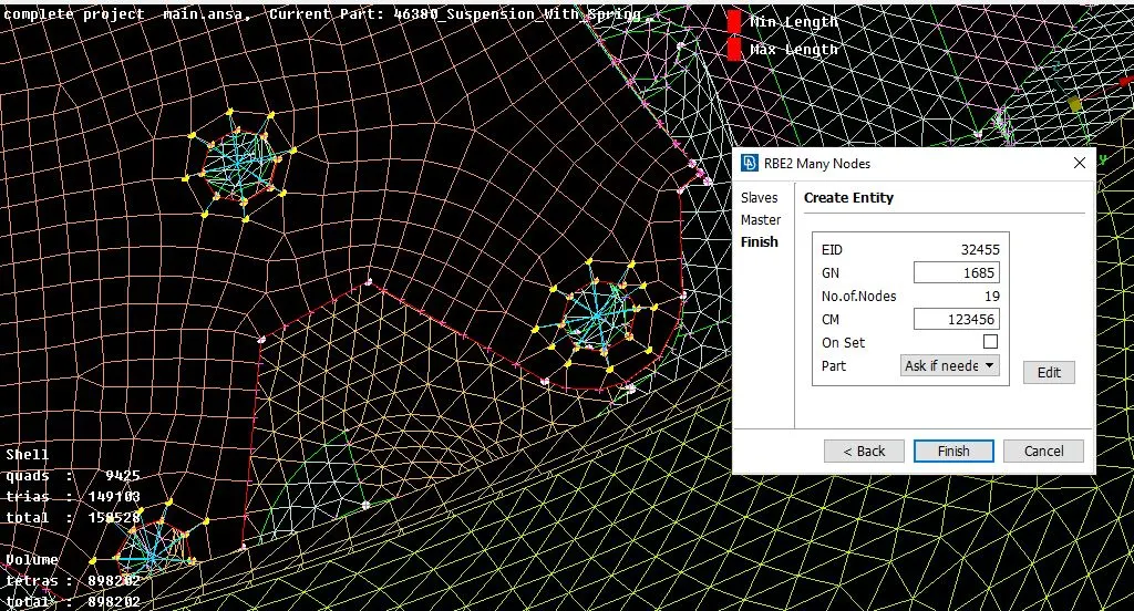
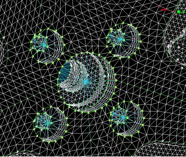
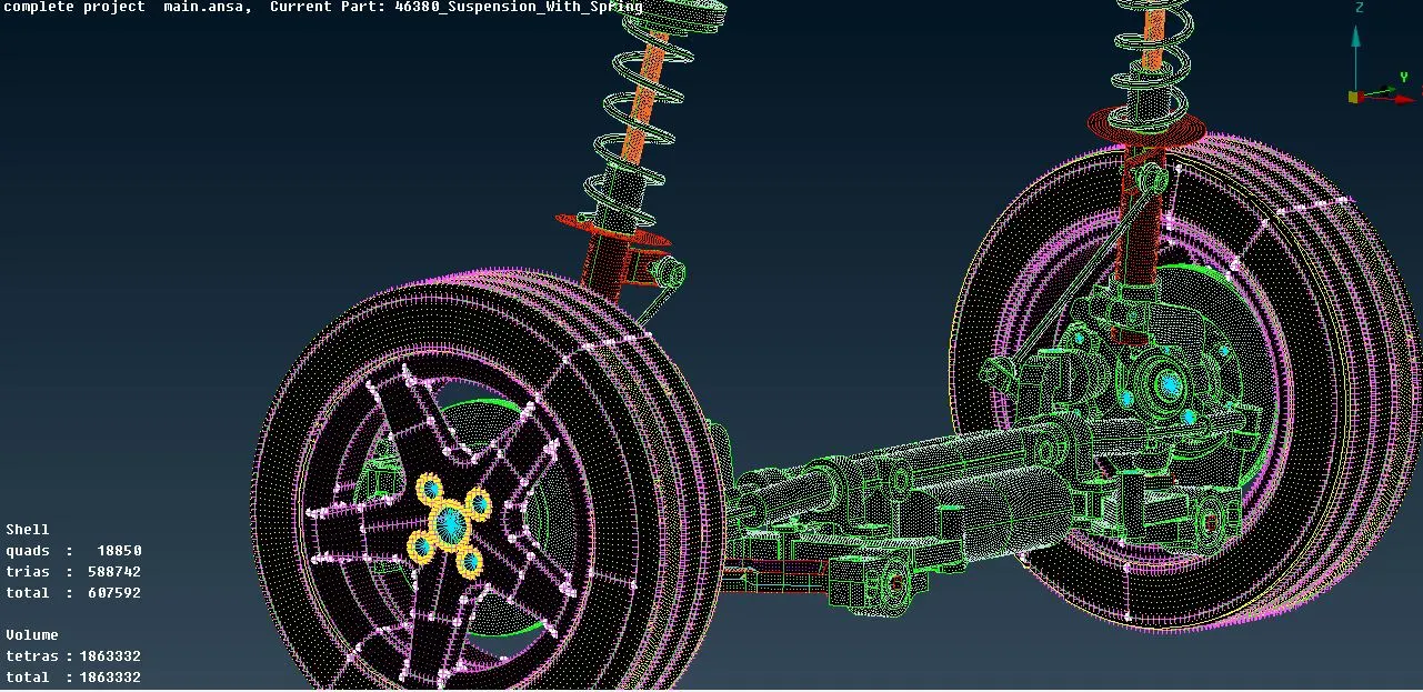
Step 12: Now meshing is completed to all parts and we need to perform connection to the all parts where it required. Here we using RBE2 elements only because the model contains studs and bolt coonections. To perform the rbe2 element connectiom we have two methods i.e, Manual method and connection manager. We will use the both option to get rbe2 elements on the model.
Step 13: To get complete model of car suspension in opposite side we need to use transformation option in utility and it will ask 3 points to select to transform the body.
Results :
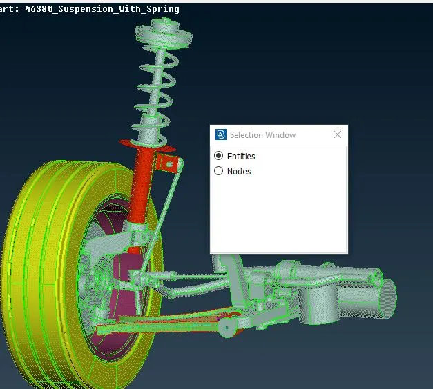
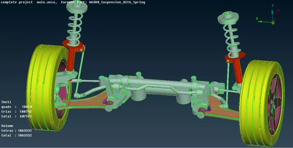
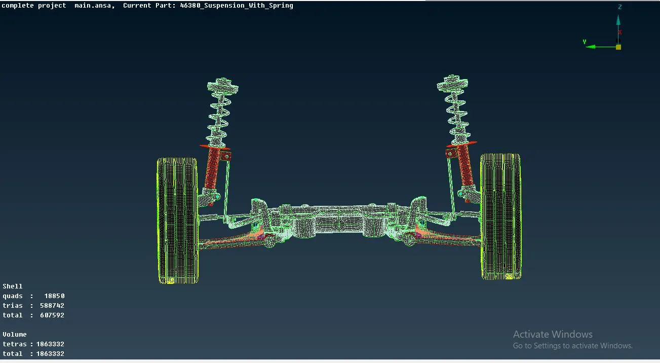
Thus we have meshed the entire model with given criteria and gave connections to all parts in model.
Conclusion :
I. Learnt extracting mid surfacing for complex geomentry.
II. Learnt cleaning the topo and defeaturing geomentry.
III. Learnt both surface mesh and volume mesh.
IV. Learnt giving connections to FE models.
V. Totally a grip on basic ANSA software.