Week -2
OBJECTIVE:
- Make a Simulink model of Doorbell using solenoid block.
- Use a thermistor to sense the temperature of a heater & turn on or turn off the fan.
Objective 1:
In the below figure, when the switch is closed the electromagnet receives electrical power from the battery and pulls the metal arm to hit the bell producing sound.
Create a situation where the switch is closed for 2 seconds and then released.
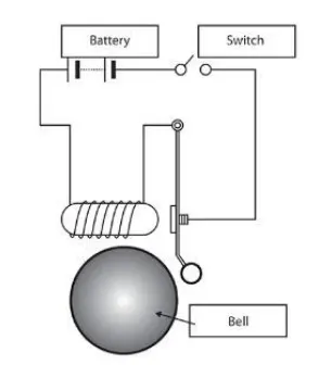
Circuit Diagram with explanation:
To make the same circuit in Simulink following blocks are required:
- Pulse generator
- Battery
- Switch
- Solenoid
- Ideal Translational Motion Sensor
- Simulink-PS Converter
- Scope
- References(Electrical, Mechanical)
- Solver
The objective is to run the bell for 2 sec, To make that happen a pulse generator is needed with the following conditions are Required
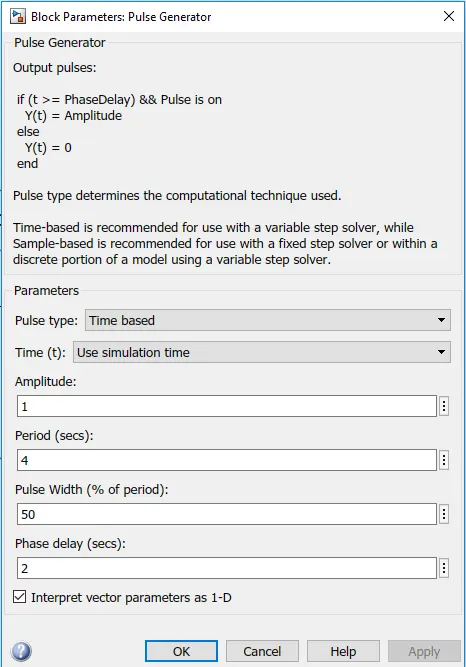
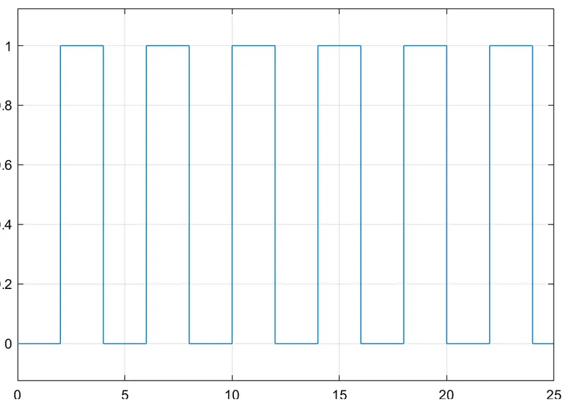
This generates a pulsating signal as follows
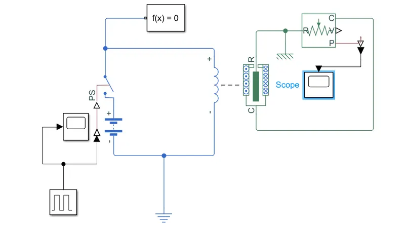
The pulse generated is converted by Simulink-PS Converter to operate a switch which is run by a battery and solenoid.
A solenoid is an electromagnetic device that converts electrical energy into linear motion. It consists of a coil surrounding a plunger which gets magnetized because of the magnetic field generated when current flows through the coil in the solenoid.
So when the solenoid gets magnetized and moves the plunger out of its shell the ideal Translational motion sensor senses the motion and sends it into the scope to plot and store the movement
Plot for plunger movement :
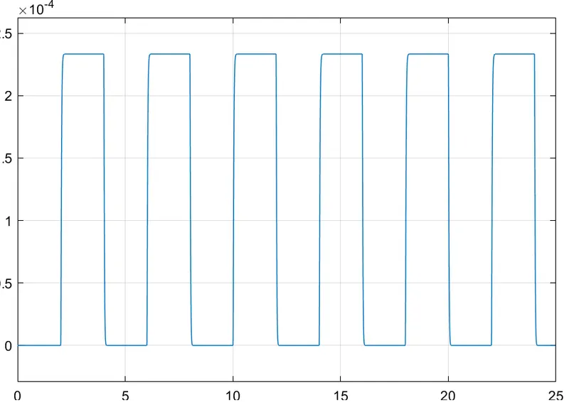
Since the damping effect also taking place so damping coefficient is increased in the parameter box of the solenoid from 0.01 to 6.
Objective 2:
Use a thermistor to sense the temperature of a heater & turn on or turn off the fan as per the below conditions:
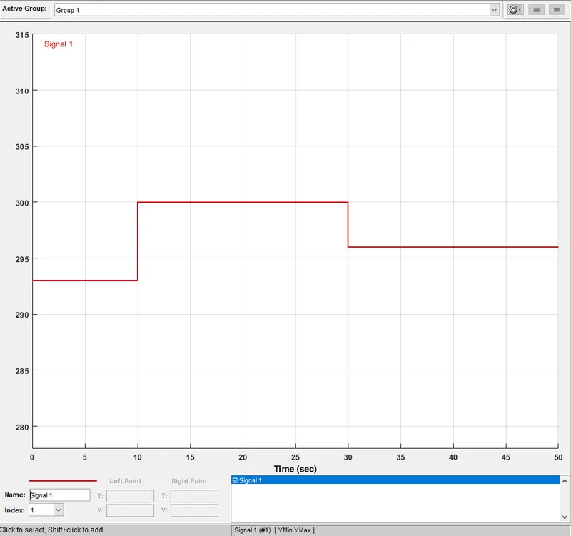
Temperature source: 20 °C from 0 to 10 seconds, 27 °C from 10 to 30 seconds, 23 °C from 30 to 50 seconds
Fan conditions: ON if the temperature above 25 °C, OFF otherwise
Circuit Diagram with explanation:
To make the same circuit in Simulink following blocks are required:
- Signal Builder
- Battery
- Switch
- Thermistor
- Voltage Sensor
- Constants
- Controlled Temperature Source
- Ideal Angular Velocity Source
- Ideal Rotational Motion Sensor
- Simulink-PS Converter
- D.C. Motor
- Scope
- References(Electrical, Mechanical, Thermal)
- Solver's
Conditions are to make the fan run when the temperature sensed by the thermistor is above 25°C.
Thermisitor:
A thermistor is a resistance thermometer, or a resistor whose resistance is dependent on temperature. The term is a combination of thermal and resistor.Thermistors are of two opposite fundamental types:
NTC(Negative Temperature Coefficient) Thermistor: In these resistance decreases as temperature rises.
PTC(Positive Temperature Coefficient) Thermistor: In these resistance increases as temperature rises.
For this Simulink circuit NTC is used.
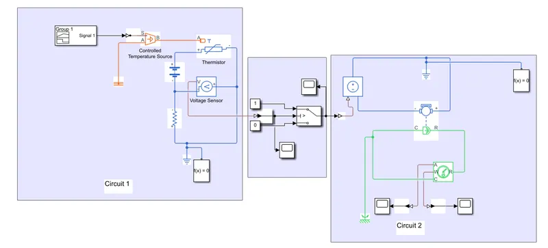
Complete circuit
Signal builder with the following signal is input to the circuit
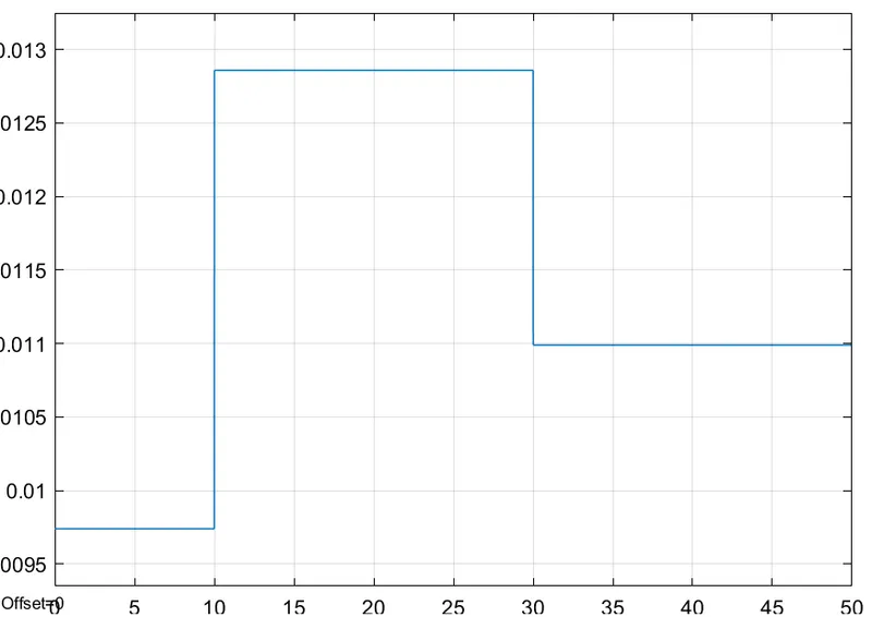
The Simulink-PS converter converts the Simulink to Physical signal input to the Controlled Temperature source which maintains the temperature difference with reference. The voltage sensor in circuit 1 detects the potential difference across resistor 1 and thermistor and gives the output to the switch which verifies if the voltage is above or below the required if-else condition.
Circuit 1
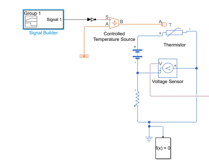
To find the Voltage at 298K voltage is displayed in the following circuit.
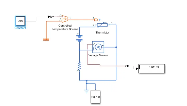
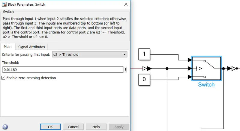
By using the voltage of 0.01189 we can use it as an if-else condition to switch on circuit 2 for turning the fan on/off.
The Voltage output in Scope is below.
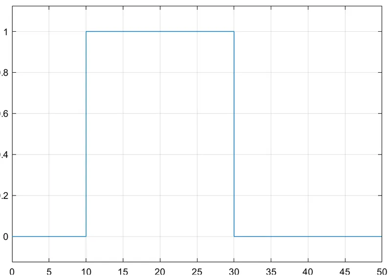
After setting this condition the switch checks and sends a 0 or 1 signal for the time period.
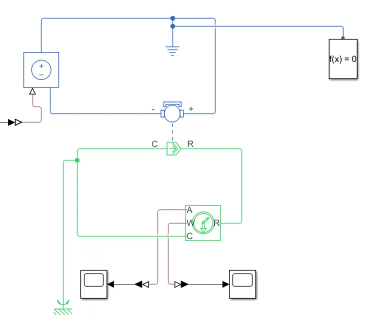
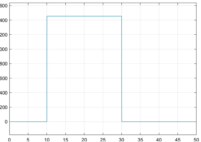
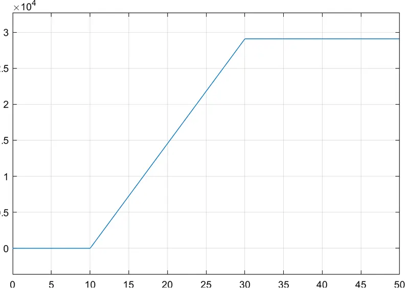
In the next circuit, the Voltage Controlled source gives the voltage to the DC motor only if the Switch returns 1 as a value and our motor connected to the fan turns on. Now to Detect the motion of the motor an Ideal Rotational Motion Sensor is attached to the R and C port of the rotor and casing and it returns the angular velocity and displacement of the motor for the time period.
Plot for Angular velocity of motor/fan and time
Plot for Angular displacement of motor/fan and time
Conclusion:
- The plot for the angular velocity of the motor shows that the motor was turned on only for the temperature of 27°C in the time period of 10-30 sec.
- The doorbell plunger operated by the solenoid comes in contact with the bell only for time of 2sec as given by the pulse generator.
References: