Week 9 - Project - Master Section Development
AIM: Create an inner plastic B-Pillar from the given master sections and Class A surface.
Theory:
Pillars:
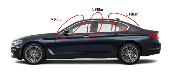
Pillars are the vertical or near-vertical supports of a car's window area.
Basically, there are 3 pillars.
- A pillar:
The pillar or the vertical bar you see holding the windshield from sides.
- B pillar:
The pillar is present in between the rear & the front door.
- C pillar:
This is where your rear window ends but on the body & not on the door.
GIVEN:
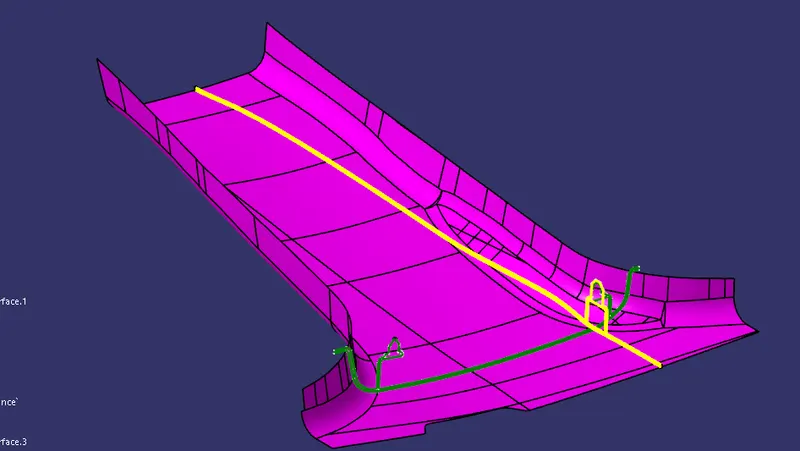
We are given two master sections and a Class A surface.
The master sections seem to give an abstract idea of the thickness of the material and the features to be given in Class B.
NOTE: Given Master section in green color is wrong so necessary adjustments were made to procure the Solid part as needed.
PROCEDURE:
- Create a Tooling Axis for the part.
- Create Class B and Class C surfaces and trim.
- Do Draft analysis.
- Create the features according to the Master section.
- Do final Draft analysis.
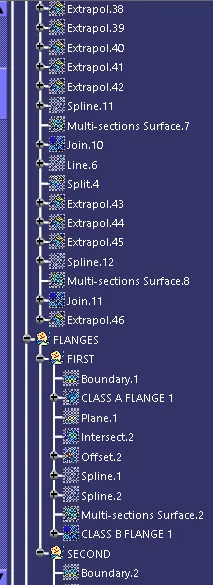
MAIN TREE: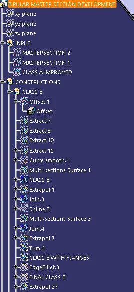
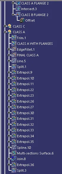
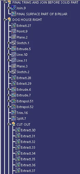
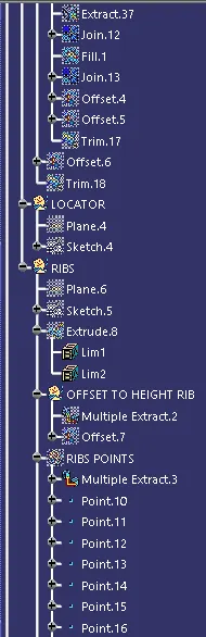
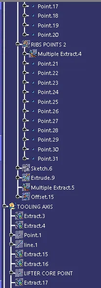
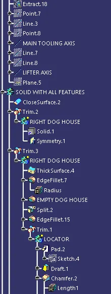
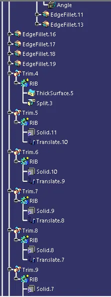
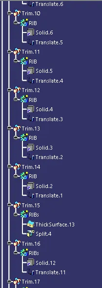
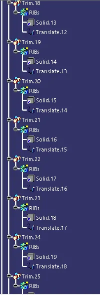
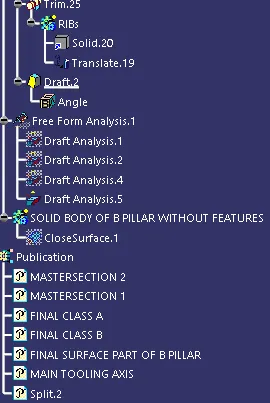
1: Create a Tooling Axis for the part.
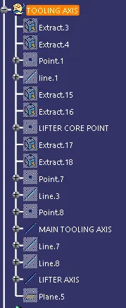
- Using the sides of the two master section 2 lines each are created and a midpoint between the lines is marked.
- 2 bisecting lines are created at the midpoints for each pair of lines created.
- Finally, the two lines are again bisected to get the MAIN TOOLING AXIS.
- Similarly, the Lifter Core Axis is also created by taking master section 2 as input and bisecting the lines at the lifter core point.
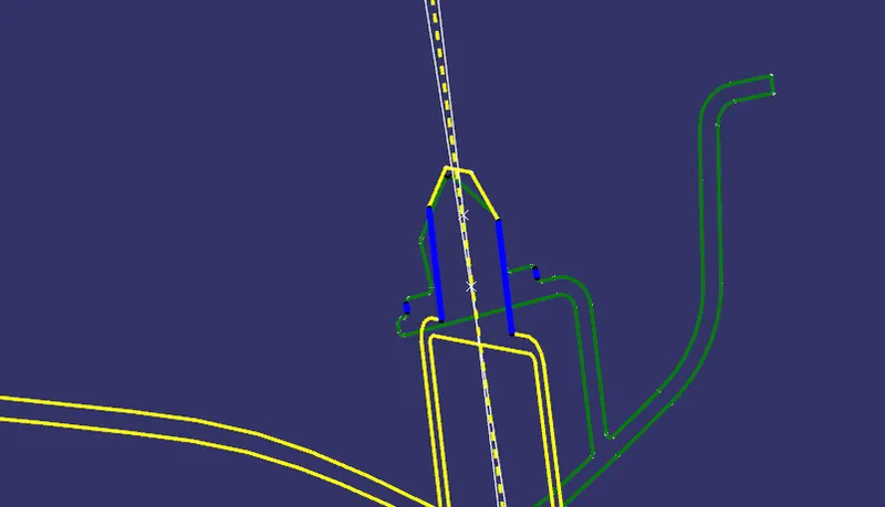
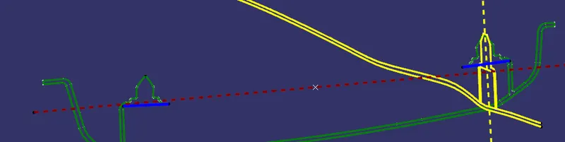
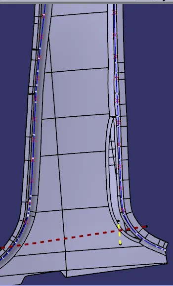
- The below figure shows the blue lines extracted from the master section to create the tooling axis.
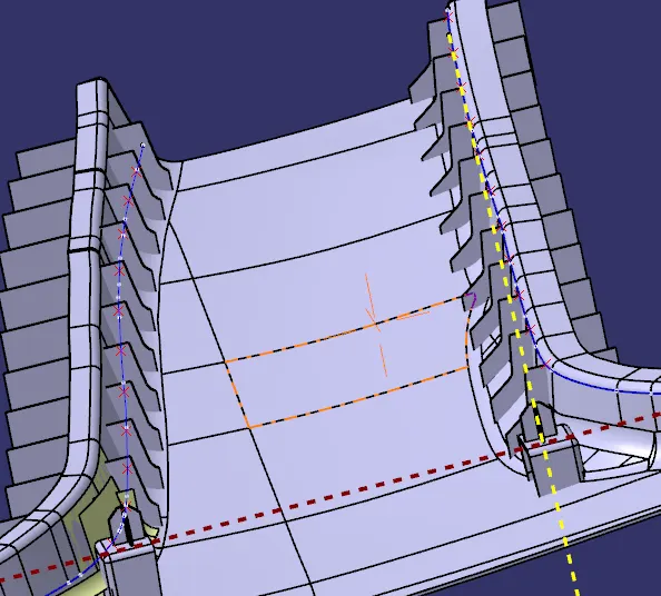
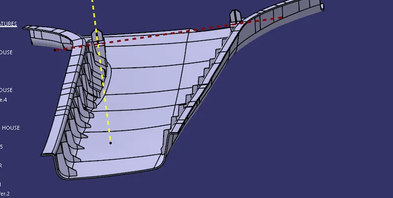
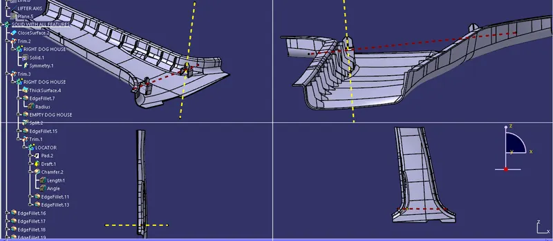
- The yellow line is the Main Tooling Axis while the Brown Line is the Lifter core Axis.
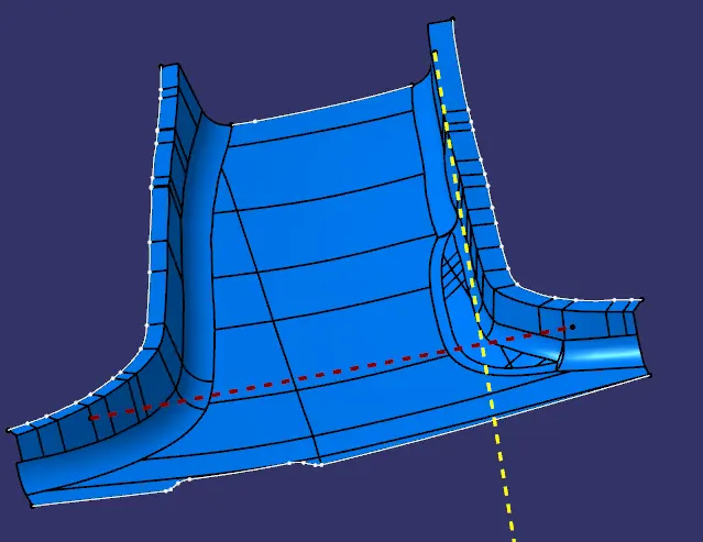
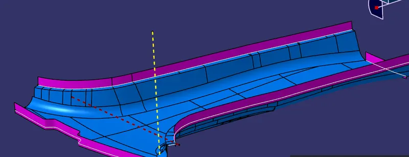
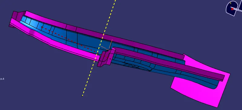
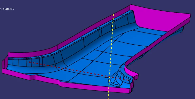
2: Create Class B and Class C surfaces and trim.
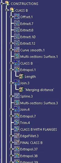
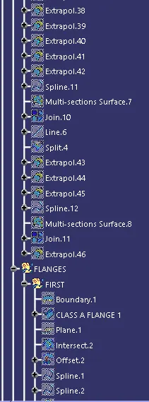
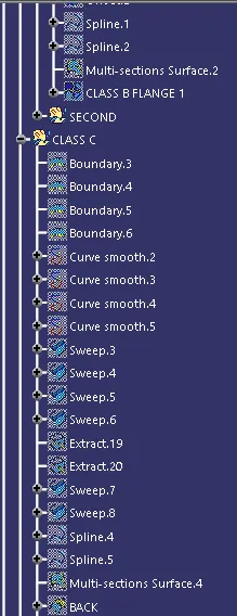
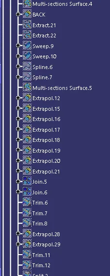
For Class B:
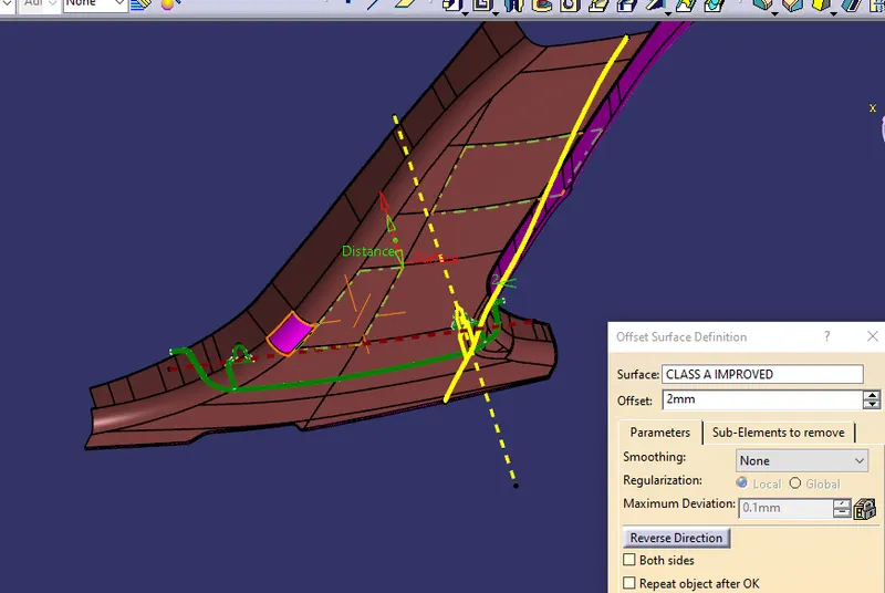
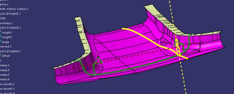
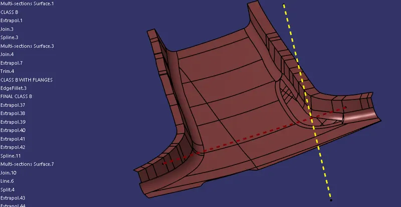
- Create an offset of class A with an offset length of 2 mm.
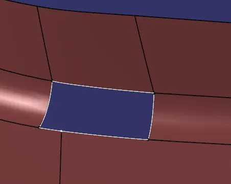
- If any patch does not happen just create a multi-section of it.
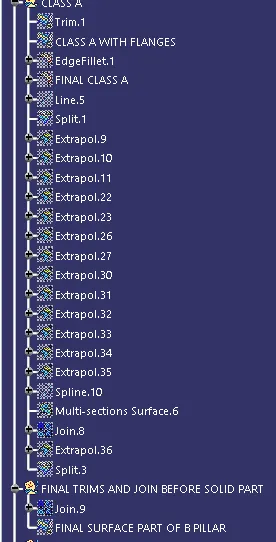
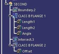
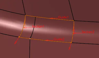
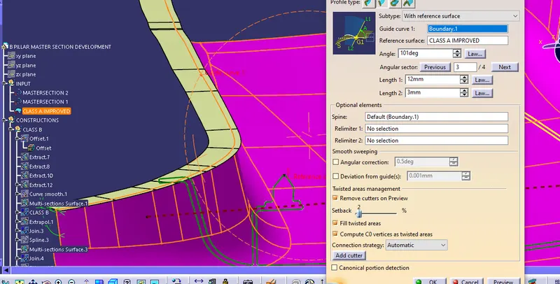
- To create Flanges create a boundary of class A then Sweep it with the horizontal master section angle.
- Offset the same for class b surface and trim them.
- Same as above if any patch does not get created just multi-section it.
For Class C:
- Create Boundaries around class A but in separate patches, so that error does not occur while sweeping it in the draft direction.
- Then smooth curve to create fewer patches of vertices getting converted into unwanted lines on Class C.
- Sweep it along the Main tooling axis in the draft direction option at 3 degrees.
- Extrapolate all surfaces and trim them to get the desired surface output.
For Final Trim and join:
- Extrapolate both Class A and Class B surfaces to avoid the wireframe error as we smooth curved the class C surface. Note: IF not possible then split the surfaces and join them.
- Then Trim the Class A and Class C surface and finally with Class B.
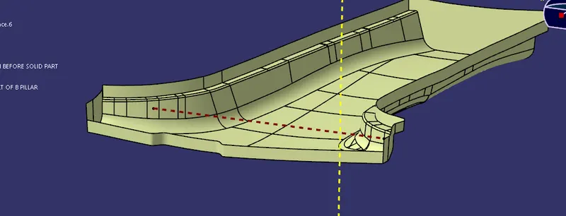

3: DRAFT Analysis:
CLASS A Draft analysis.
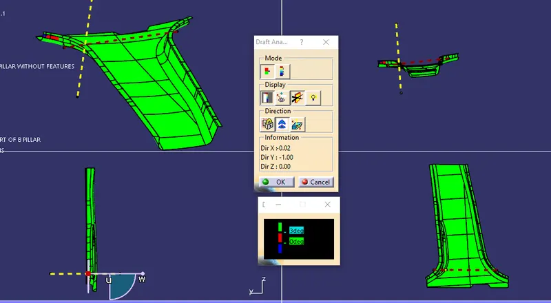
Solid body without features Draft Analysis:

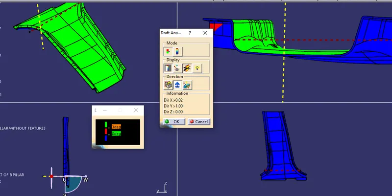
4: Create B side Features.
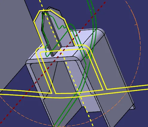
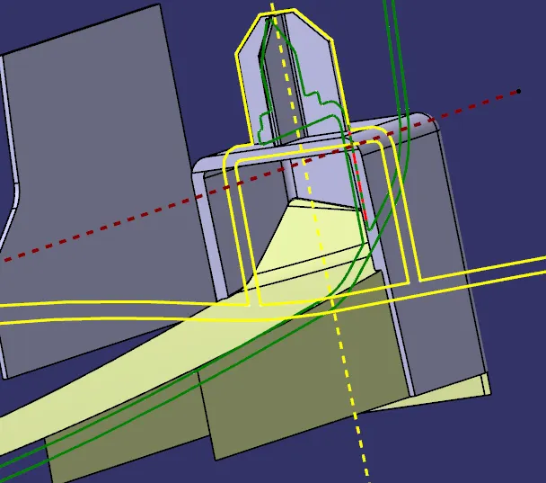
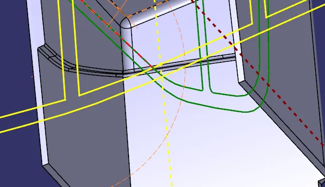
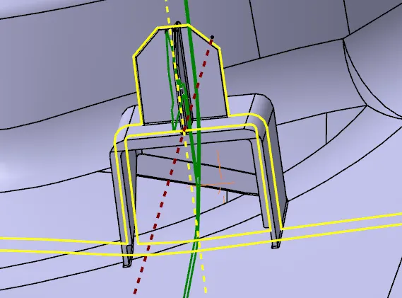
For DogHouse with 4 Way Locator:
Procedure:
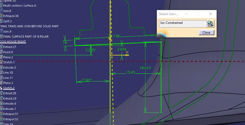
- Extract the necessary details of the master section for creating a Doghouse.
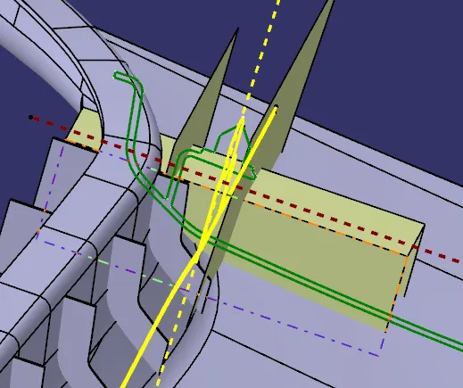
- Create a sketch for the outer box of the doghouse.
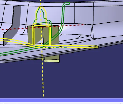
- Extrude the surface and trim it with the inner and outer walls of the other master section.
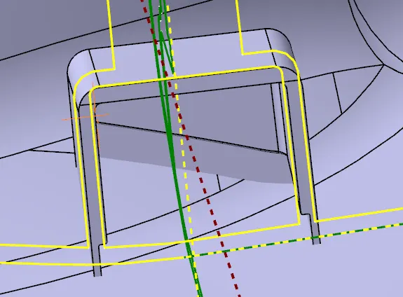
- Use a thick surface to give the surface a 2 mm thickness and create a solid of it.
- Use Edge fillets of 1 mm and 3 mm as per the master section.
- To create a Coring inside which we need to do according to the design rules the inside wall thickness should be 1mm and a draft of 0.5 degrees with a coring height of 3-6 mm from the base.
- Also, the inside fillets which are not mentioned should be around 0.25mm.
- Using the master section extract the longer edge and measure it.
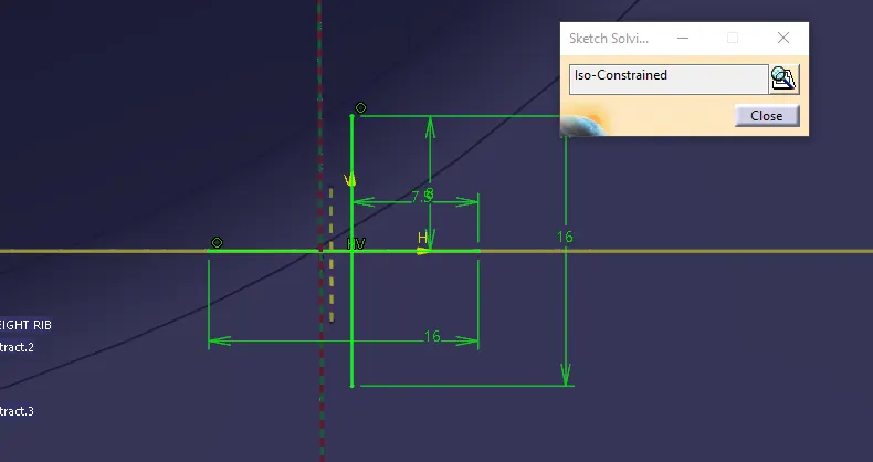
- Now create a sketch with the cross of it on top of the Doghouse.
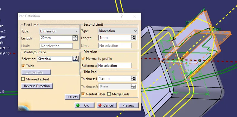
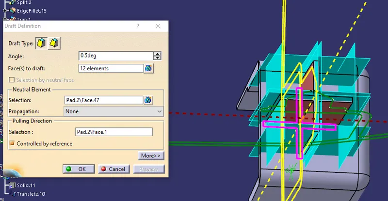
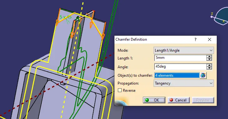
- Maintaining all the design rules for the 4-way locator, Height is given as 20mm and chamfer of 5mm X 45 degrees, Neutral thickness of 1.2 mm is taken fillets of 0.3 mm are taken along with the Draft angle of 0.5 degrees.
- Finally, using the union trim command of boolean operations we get the final doghouse with a 4-way locator.
For RIBS:
Procedure:
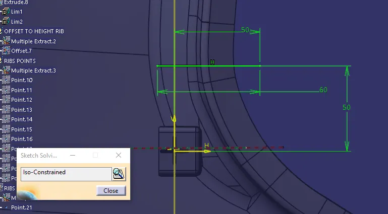
- Create a Sketch at 50 m from the dog house in the Z direction.
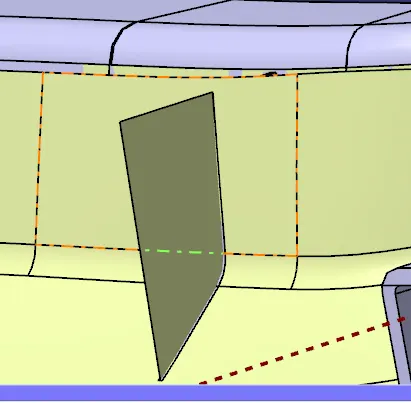
- Give adequate length and extrude the surface along Y and thicken both sides up to 0.4 mm and a draft of 0.5 degrees according to design rules.
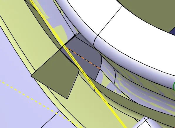
- Extract and offset the surface around the first rib and split the rib.
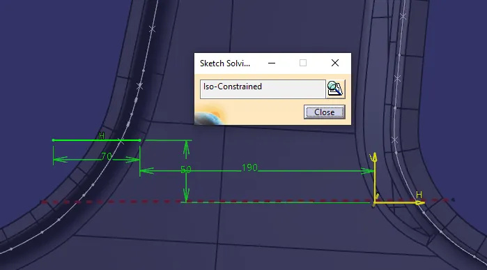
- Now using the boundaries of Class B create multiple points at 50 mm equidistant and copy and paste with link command
- Use translate to move each of the ribs, Do the same steps for the other side ribs.
- Finally, Union trim it with the part body to get the final body
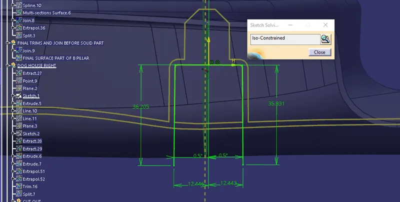
5: Final Draft Analysis.
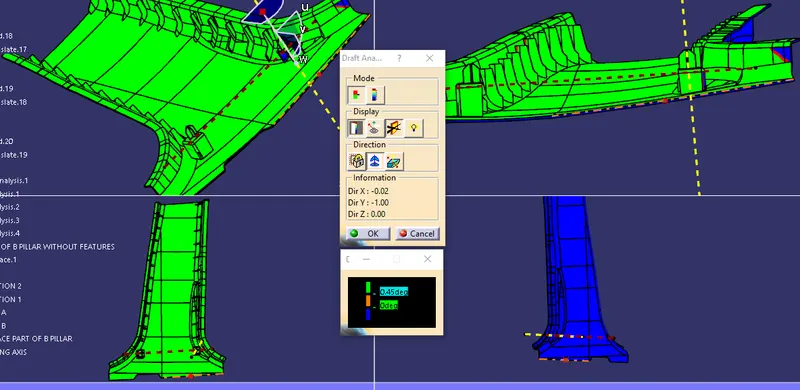
DRAFT ANALYSIS of Final part along main tooling axis for ribs:
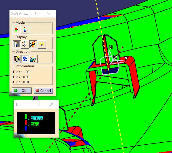
For DOG house along with lifter core :
CONCLUSION:
Successfully created a solid part from the given class A and master section with all the engineering featured with the adequate design rules were respected and maintained.