Week 9 - Attachment Feature Creation - Challenge 1
AIM: Create the rib for the Centre console coin holder considering the design rules.
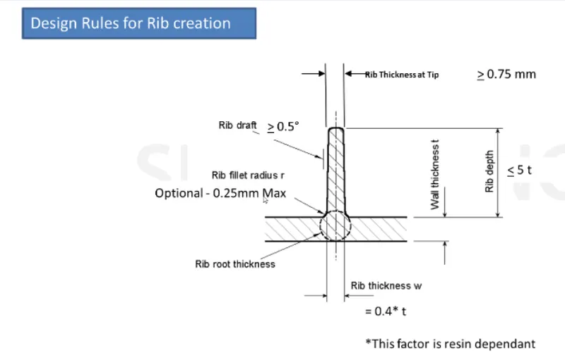
RIBS =
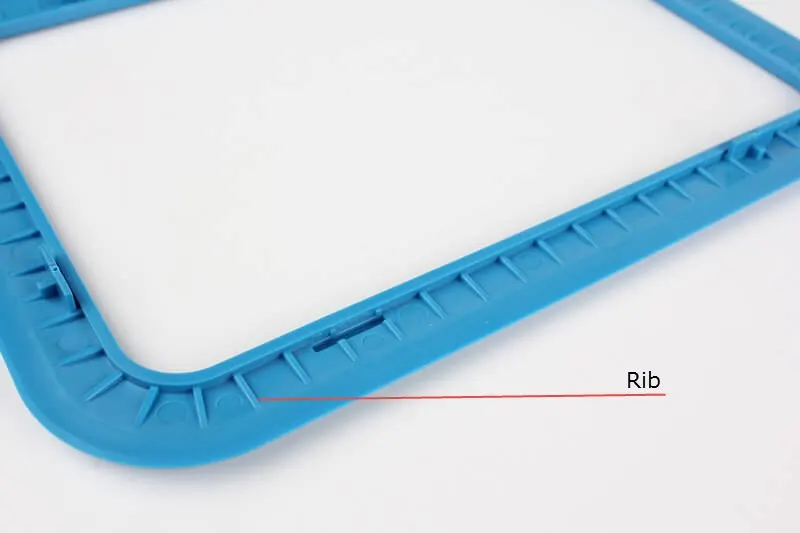
Ribs are thin wall-like structures that add support and rigidity to injection molded parts. They are thinner than primary walls and are used to support these walls, as well as bosses, by running perpendicular to these structures. Ribs are often used to replace thick wall sections to avoid sink marks, warp, and voids.
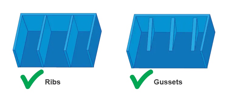
GUSSETS:
Gussets are a subset of ribs that are often used to support bosses, though they can support walls and other ribs as well
DESIGN RULES for RIBS:
- Rib thickness - Ribs should be designed to be 40 percent of the nominal wall thickness. Thinner does not provide much structure and may be hard to fill. Thicker ribs are tempting, but they can begin to introduce sinks on the cosmetic surface.
- Rib height - The Rib height should be greater than or equal to 5 times the wall thickness.
- Rib spacing - Increase the number of ribs rather than their height to increase stiffness. Ribs should be spaced a minimum of two times the nominal wall thickness apart from one another. or it can be done in the ratio as well. The ratio will be of a height to width ratio.
- Minimum thickness at the tip - We have to ensure that the minimum thickness at the rib tip must be 0.75 mm
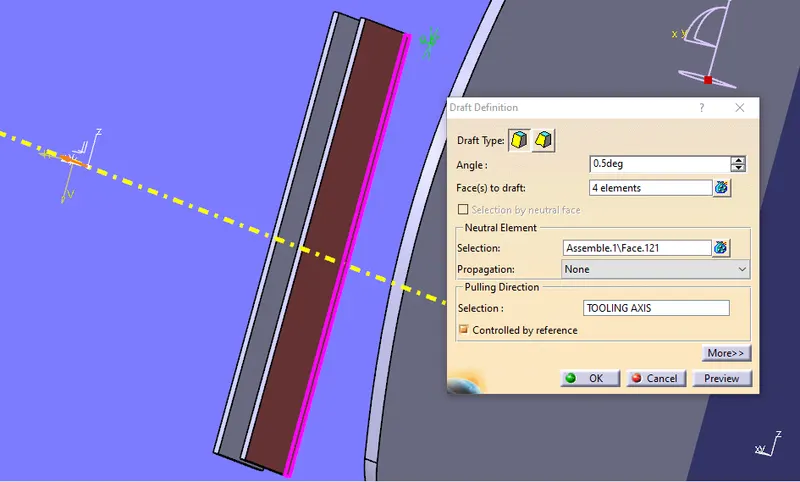
- Draft - A minimum 0.5-degree draft will ensure that they release from the tool during molding.
- Radii - The fillets provided in the ribs should be in the range of 0.25mm to 0.5mm. Generally, it is recommended to give 0.25mm fillets.
Given data:
t = 'Wall Thickness' = 2.5mm.
To calculate the following data using rib design rules
θ = ' Rib Draft' = 0.5°
r = 'Rib Fillet radius' = 0.25mm
tt = 'Rib Tip Thickness' = 0.75mm
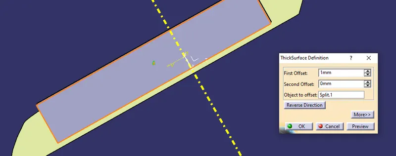
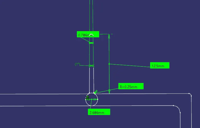
w = ' Rib Thickness ' = 0.4 * t = 0.4 * 2.5 = 1mm.
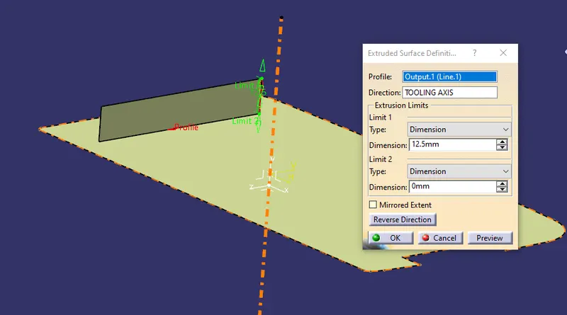
d = ' Rib Depth ' ≤ 5*t = 5*2.5 = 12.5mm.
MAIN TREE:
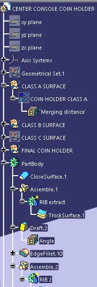
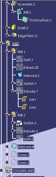
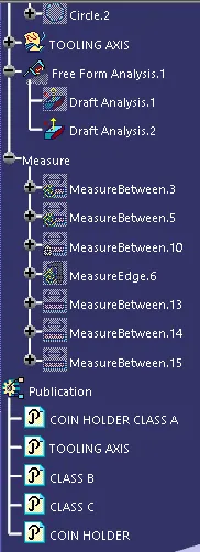
Create a Tooling Axis for the Class A surface.
TREE:
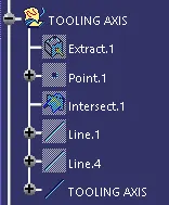
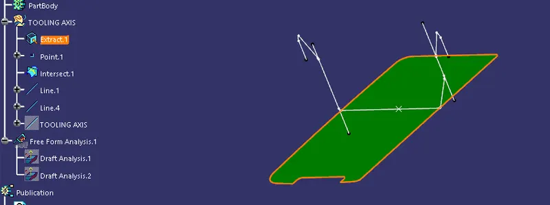
- Create a point on the class A surface to move the main tool for component creation on the base surface.
- Mask an axis over the point created with the same directions as the main axis
 .
. - Using Intersect command from Generative Shape design select the YZ plane as the first element and the class A surface as the second element
 .
. - After creating the intersecting lines select the Line command and join the vertices which show the most possible draft angle manufacturable.
- Bisect those two lines over the axis point we created
 .
.
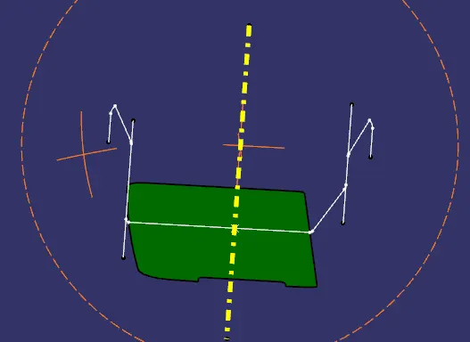
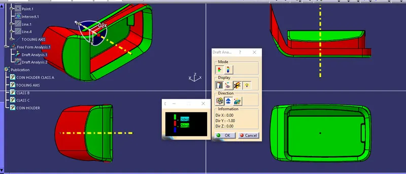
OBJECTIVE 2: DRAFT ANALYSIS of Class A surface:
Note: Class A surface was constructed wrongly as there is no draft angle on the bin walls of the coin holder.
PROCEDURE:
- After Tooling Axis Select the Feature Draft Analysis option from the Insert Option
 .
. - Select the element to analyze.
- Next click on Use the compass to define the new current draft direction option and make it align with the tooling axis by dragging it to the axis
 .
. - If the color appears blue just click the invert option on the right side of the draft direction axis button.
OBJECTIVE 3: Creating RIBS on the base of the Coin Holder.
TREE:
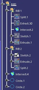
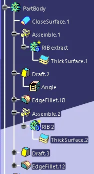
SKETCH:
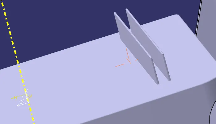
Extract the base surface and create a sketch on it.
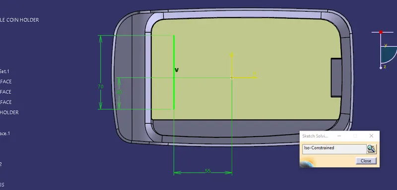
In Generative Shape Design, Extract the surface up to 12.5 mm as calculated.
In part design, Give the thickness of the rib as per the calculations (1mm).
A draft angle of 0.5 is estimated.
Fillets of 0.25mm are given to all faces.
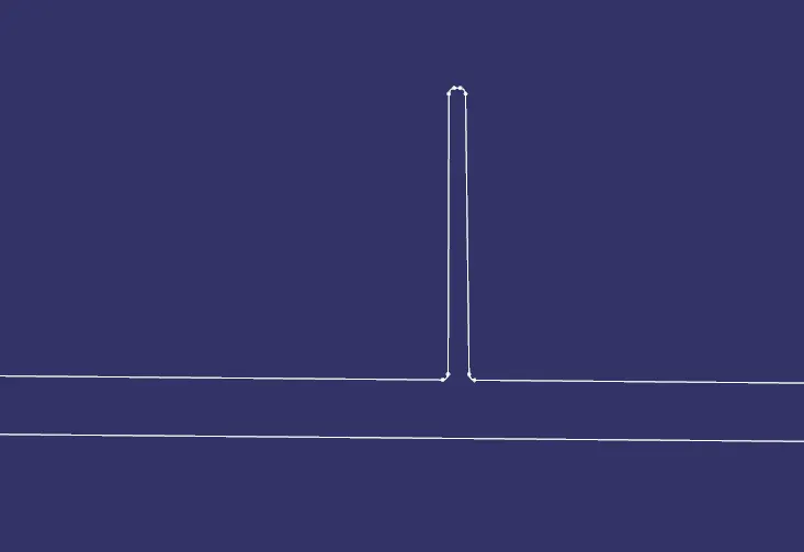
An Intersection showing the rib with its dimensions to see if it satisfied the design conditions.
SECOND RIB:
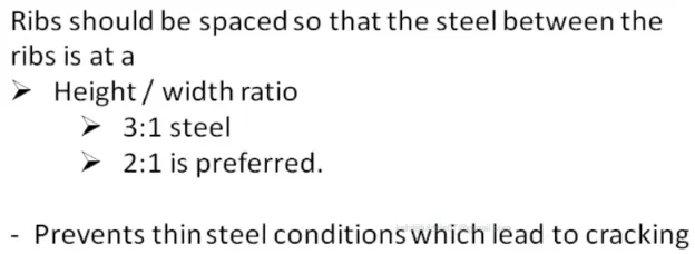
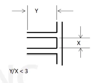
For the location of the second rib, we know the value of Y which is rib depth as 12.5 mm.
So gap 'X' should be Y/3
therefore, 12.5/3= 4.1667mm
but considering the thickness of ribs adding 1 mm to both sides, we get 4.1667+1=5.1667mm.
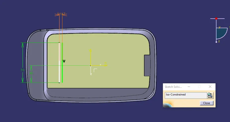
Similarly to the first rib do all the processes the same.
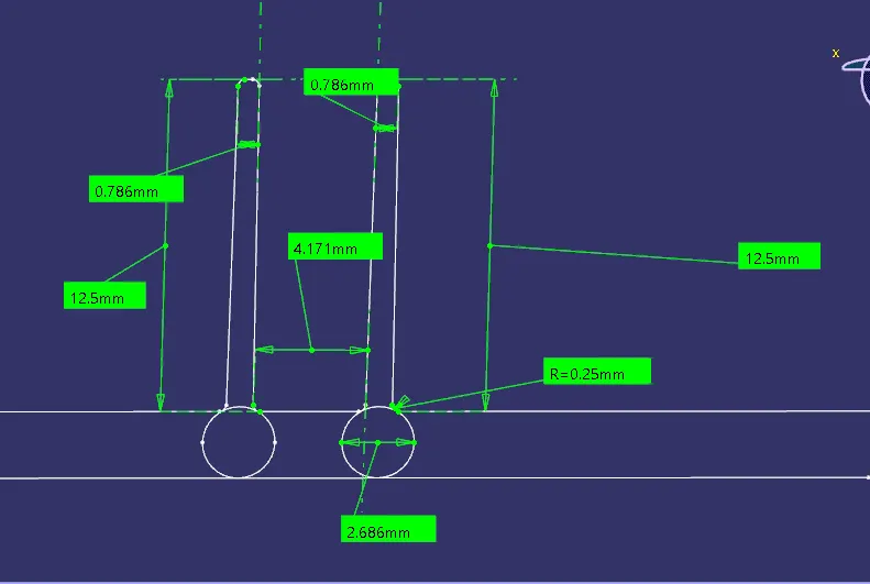
RIB root Thickness for both ribs is the same 2.686 mm which is almost equal to 2.5 m thickness and acceptable in manufacturing.
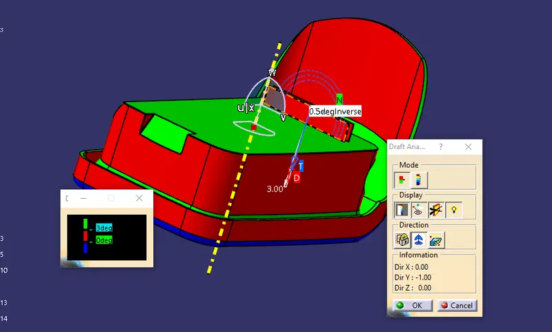
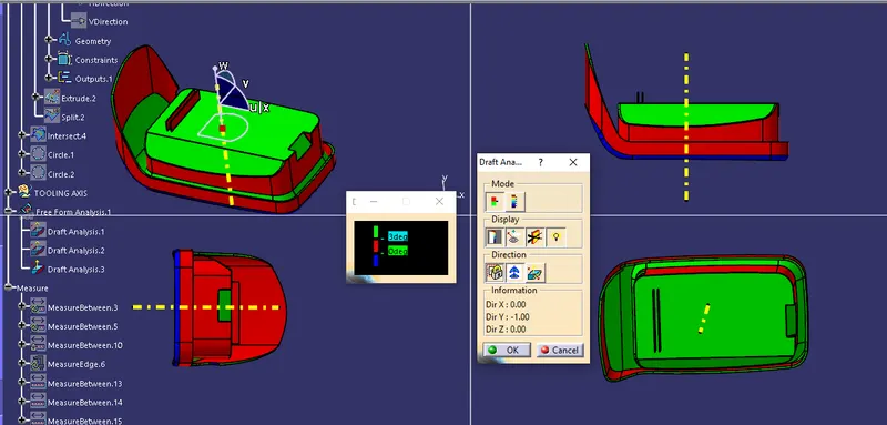
OBJECTIVE 4: Draft Analysis on Final component with ribs.
PROCEDURE:
- After Tooling Axis Select the Feature Draft Analysis option from the Insert Option.
- Select the element to analyze.
- Next click on Use the compass to define the new current draft direction option and make it align with the tooling axis by dragging it to the axis.
- If the color appears blue just click the invert option on the right side of the draft direction axis button.
CONCLUSION:
Created ribs on the base surface of the coin holder to add rigidity and strength to the component with design rules as applicable.