Week 8 - Challenge 1 - Draft Analysis on a Fan Cover
AIM: Create the tooling axis for the given Fan cover model meeting the requirements of the draft angle and perform the Draft analysis on the model.
THEORY:
For any plastic component to be designed using injection molding a slightly tapered surface needs to be provided for smooth movement of the product after it is manufactured inside the core and cavity.
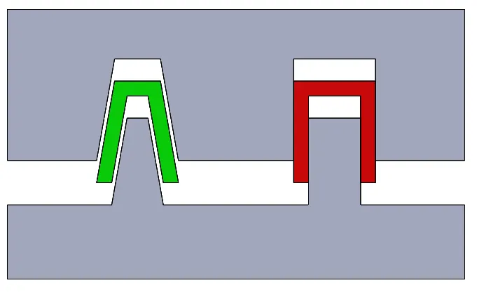
In the above image, the left side component can be seen as sliding easily out of the core and cavity as it has a slight angle with the direction of the tooling and hence it is easy to manufacture. But the right-hand side component is getting stuck with the core and cavity hence can create deformation as it is already heated and sliding will deform the part. To avoid this a simple draft is given to the design structure and accordingly to core cavity members.
TOOLING AXIS:
It is the direction that corresponds to the reference from which the draft faces are defined and the product to be manufactured.
DRAFT ANGLE:
It is the angle that the draft faces make with the main tooling axis. This angle may be defined for each face.
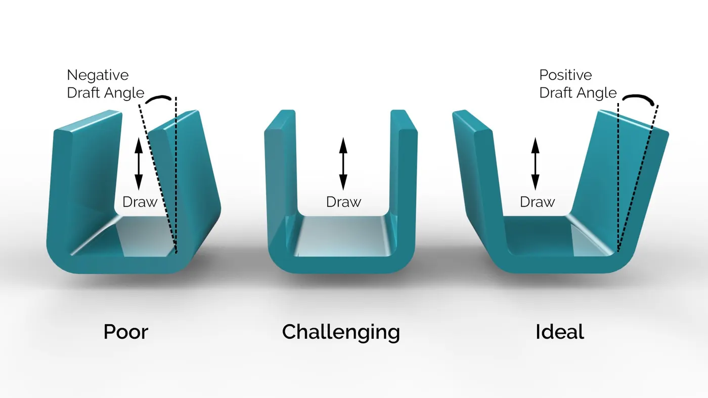
The draft angles should be given according to the needs of the product. Industry prefers the minimum draft angle to be around 3°.
Guidelines for design draft angle:
- Material shrinkage – Some materials shrink more than others. In general, the higher the shrinkage, the larger the draft angle needed to prevent ejection issues.
- Height and shape of wall or feature – A shallow single straight rib having not enough draft causes fewer problems than a high cylindrical wall.
- Surface texture – A polished surface requires a smaller draft angle than a surface that is textured.
DRAFT ANALYSIS:
This command enables you to detect if the part you drafted will be easily removed from the core and cavity.
Procedure for Creating tooling axis:
- Create a point on the part from where the tooling of the part is most feasible.
- In this case, the tooling axis from the top would be the most efficient and cost-effective.
- By using a point in the center /sphere option, a point 1 is created.
- Create a dummy tooling axis by using the axis command and placing it as the main axis.
- Using intersect command of the generative Shape Design select the axis first in our case YZ plane and then the next element is the fan cover which makes a sketch of the component perpendicular to the Y axis.
- Create a line using the Line command to check for draft angle and bisecting lines for the sides you consider as a problem for the minimum draft and not possible to manufacture.
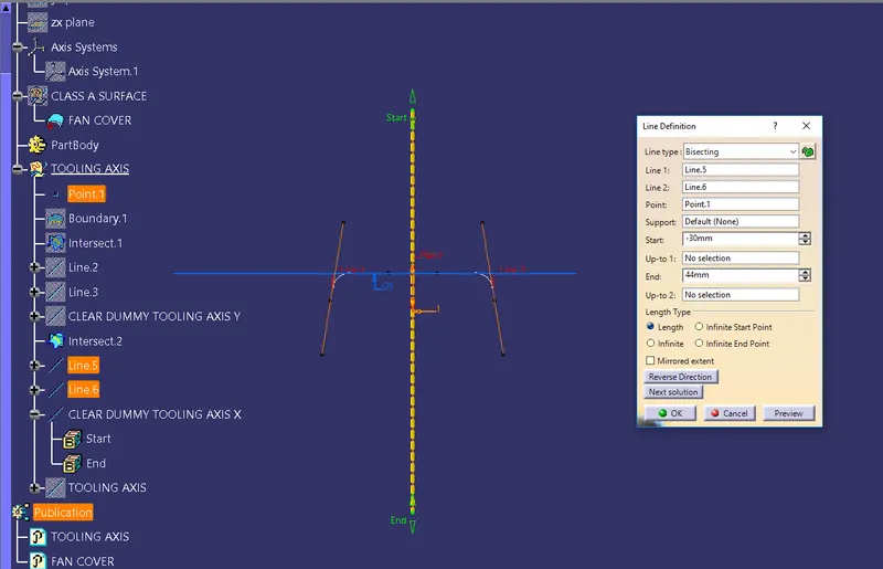
- Using bisecting lines command from Line create a line passing through the two lines and check if is going through the point created to pass through.
- Do the same for the XZ plane.
- Now make a bisecting line through the two lines we got from the above two axes.
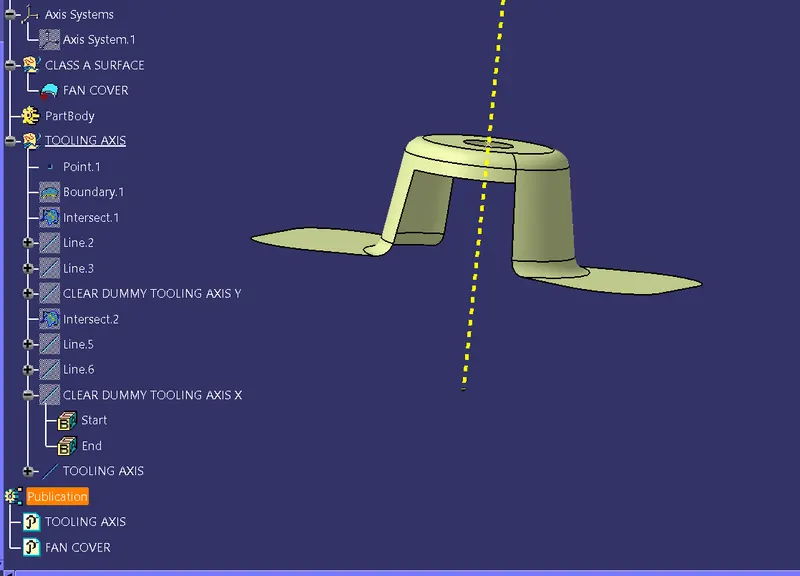
- This line is your tooling axis.

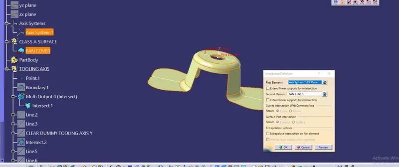
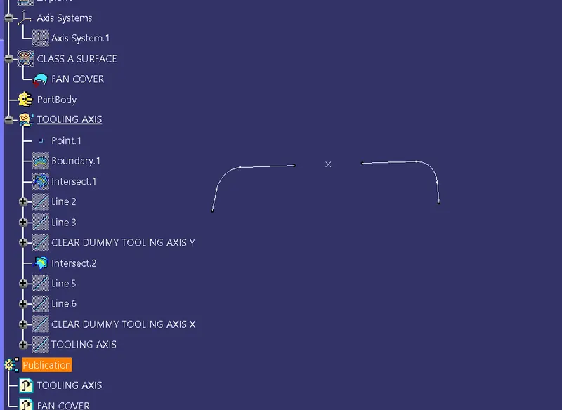
In the YZ plane of the axis, the Intersection command is used.
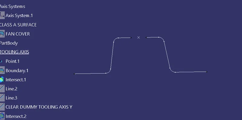
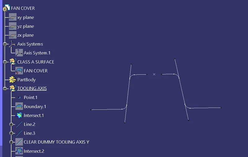
Using bisecting command to create a line passing through the two lines which may not have the minimum draft angle.
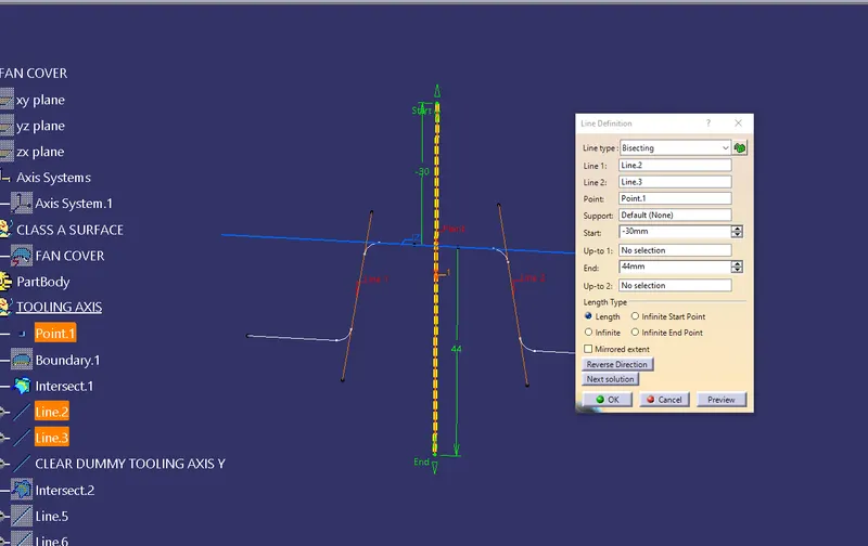
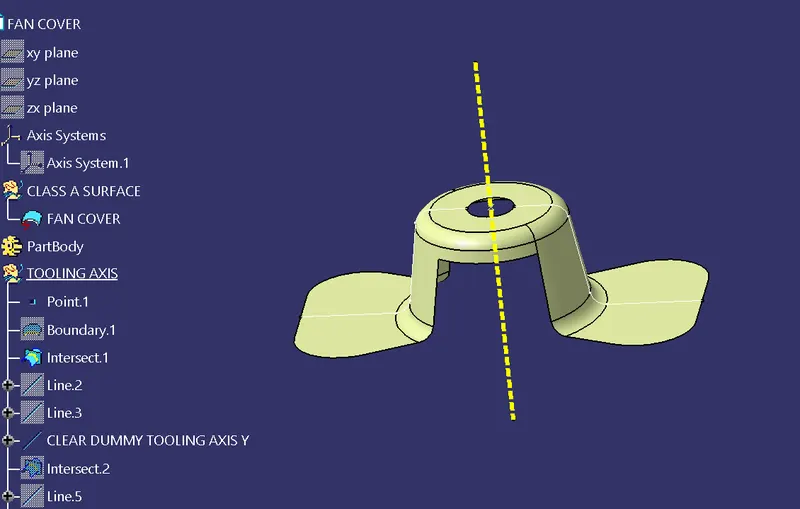
Dummy tooling axis clearing Y-axis.
Similarly for the
XZ plane,
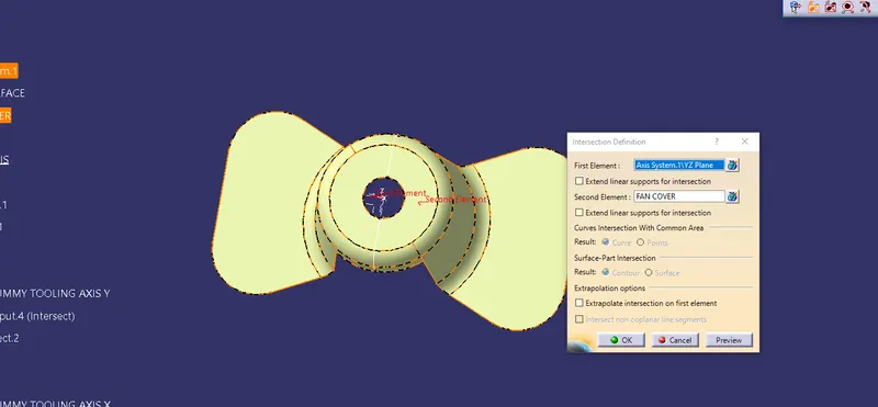
Intersection command used to create section along the XZ plane.
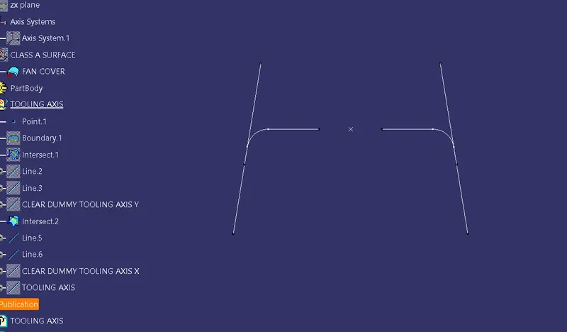
Bisecting the above two lines
TOOLING AXIS:
PROCEDURE FOR DRAFt ANALYSIS:
- Change the Shading option from the view mode toolbar to materials.
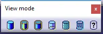
- Then click on the draft analysis button.

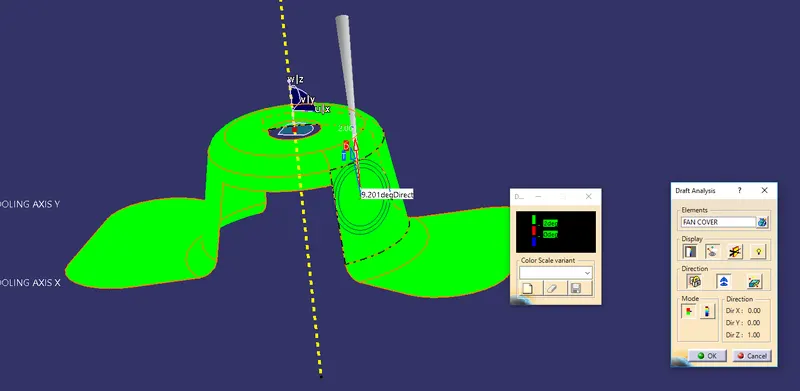
- A Dialogue box appears and then select the axis from the direction option and place it along the tooling Axis we found with the Z direction point in the direction of the tooling axis.
- Check for the Color change as in the color bar if the angle is below the predetermined angle then the color changes to red if it maintains the required angle then the green color depicts that the component can be manufactured with this draft angle easily.
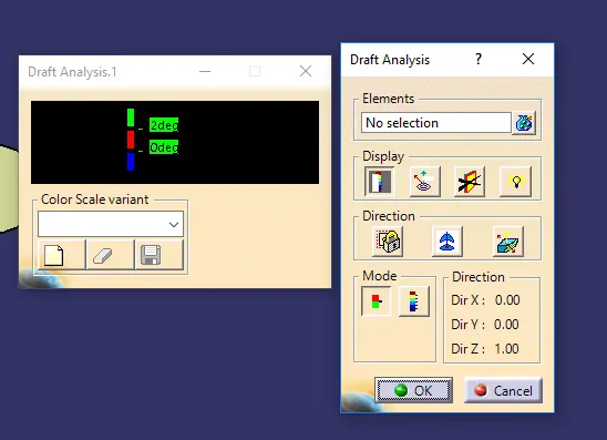
AXIS along Tooling direction.
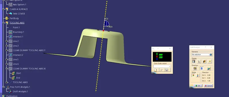
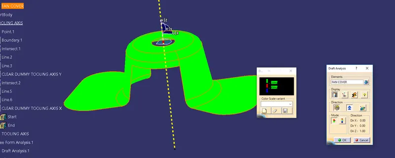
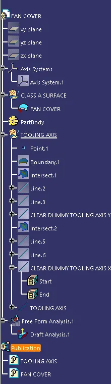
TREE STRUCTURE:
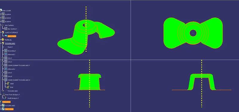
ORIENTATIONS:
Publication: To publish select the publication command from the tool option in the main ribbon and select the tooling axis and fan cover to be published.
CONCLUSION:
The minimum Draft angle of 3 Degree was achieved and the draft analysis gives us the introspect of passing the Fan cover to be manufactured by the injection molding process.