Advanced Sheet Metal Design Using NX Cad Challenge_7_ Metal bracket-II
Title of the Project: Design a metal bracket II using NX CAD Sheetmetal
Objective : Create a metal bracket in sheetmetal NX CAD
Introduction:
Sheet metal is one of the most versatile and widely used manufacturing methods. It has a significantly lower cost than machining cavities into metal blocks. For making a sheet metal component following steps are performed:
- Material selection
- Wall thickness
- Bend radii
- Bend allowance
- K Factor
- Bend reliefs
- Manufacturing process
- CAD platforms
Design methodology:
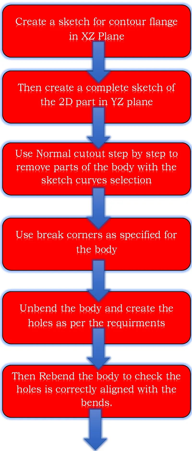
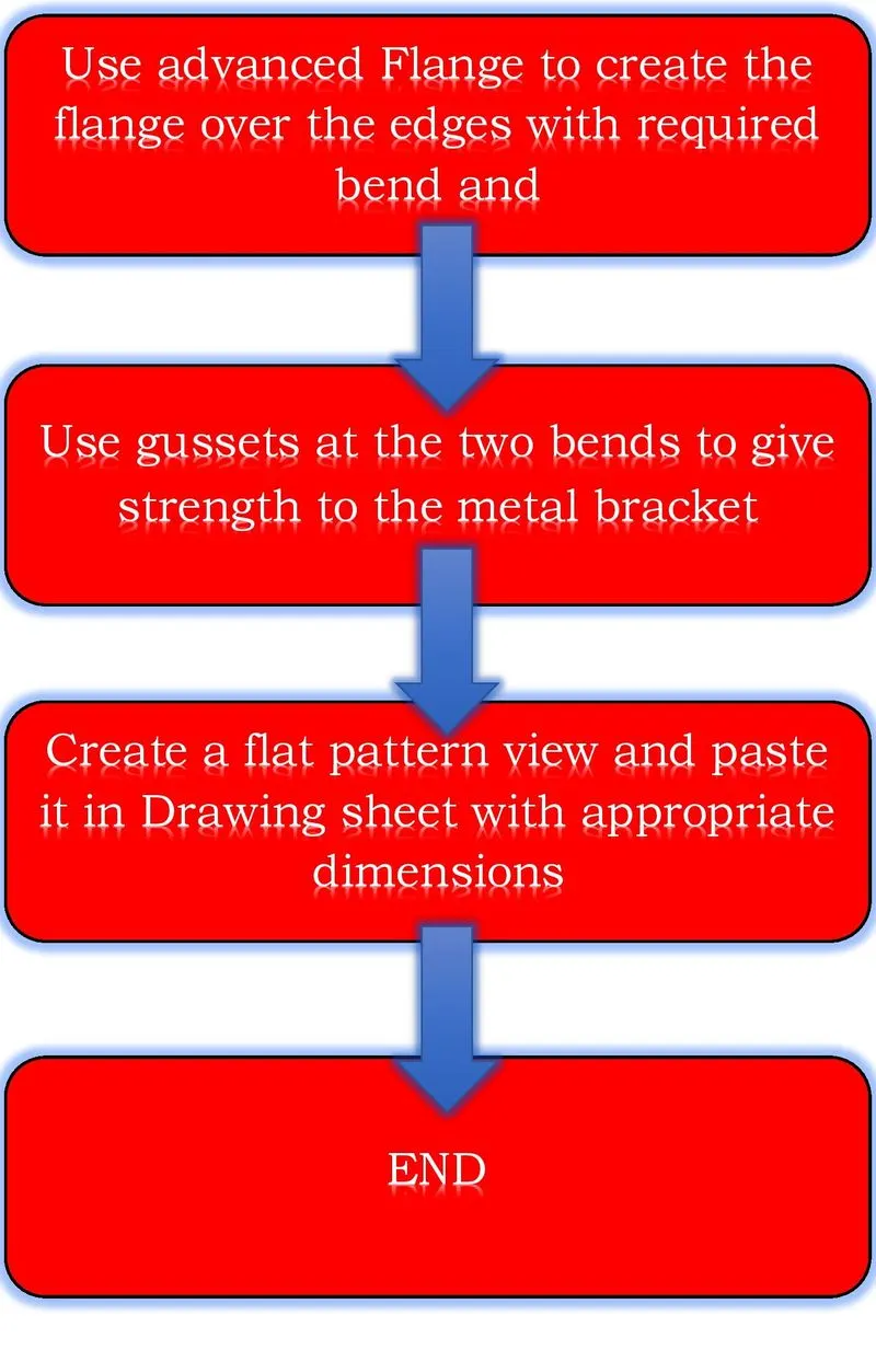
Description:
All the tools and features used are as below:
1. Sketch:
It is used to create two-dimensional figures in Software for operations/tools to be applied and is basic for any design.
2. Advanced Flange:
Creates a sheet metal enclosure on the solid body over the selected edge with advanced features
3. Normal cutout:
This command creates a cutout through the body normal to sketch.
4. UNBEND:
It is used to flatten a bend to its reference surface.
5. HOLE:
Used to create holes in the given body according to the size of the body and screw fit type.
6. Gusset:
It is used to strengthen the sheet metal at bend areas
7. REBEND:
Restores a bend from its flattened section to the original.
8. Break Corner:
Creates a smooth filleted(radius) corner on the sharp corner of the formed sheet metal part.
9. Flat Pattern:
Creates a flat pattern of the sheet metal body with all its edges and bend areas completely horizontal with a stationary face of the body.
Views:
Top view:
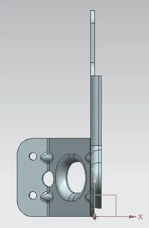
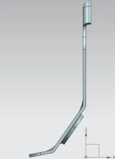
Side View:
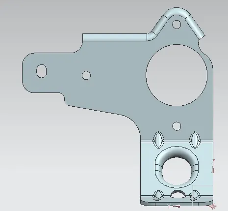
Front View:
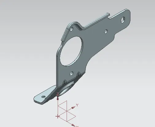
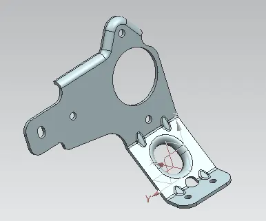
Isometric View:
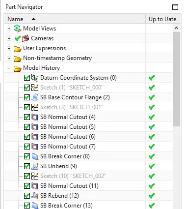
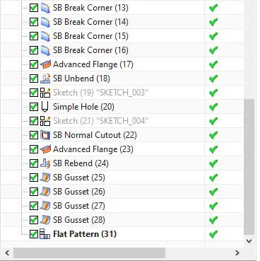
Part Tree:
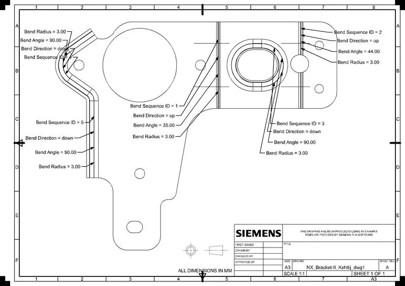
Drawing Sheet:
Conclusion:
The metal bracket was successfully created in the NX CAD sheet metal Application using the various tools and features.