Week 9 - Attachment Feature Creation - Challenge 2
AIM: Create the boss and Dog House for the Centre console coin holder considering the design rules mentioned.
DESIGN RULES:
1. SCREW BOSS:
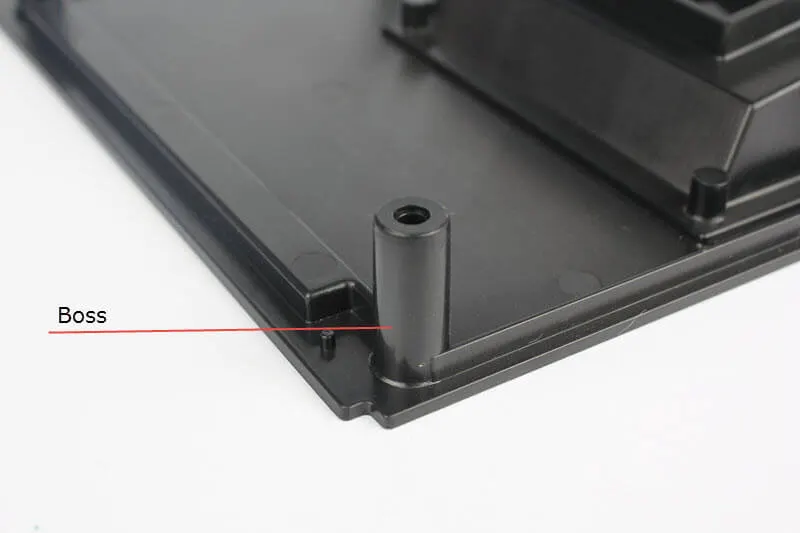
Boss refers to a mounting feature that will receive a screw or thread-forming screw. In computer-aided design applications, a boss is a feature used to describe a type of extrusion to mate with other parts precisely via a screw.
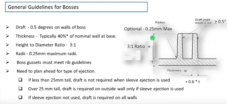
- The outside diameter of boss=2 to 2.4 *D
- Hole up to 0.3*t
- Merge base thickness W=0.6*T
- Fillet = 0.25mm max(must not violate 0.4*t)
- Draft angle inside out= 0.5 degrees
- Height to inside diameter ratio=H/B<3
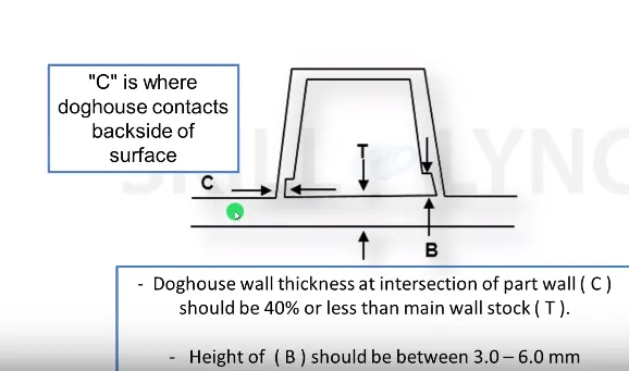
2. Dog House:
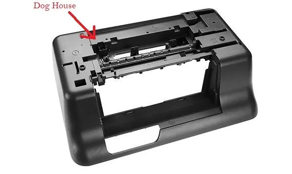
The dog house is an engineering feature used in the plastic trim design. Dog houses are used as supporting features. Sometimes other engineering features like snaps; locators, etc. are mounded on them to increase their
strength.
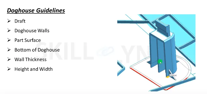
- Draft 1.5 degree on all walls
- Intersection of part wall Thickness= 0.4* T
- Height =3<->6mm
- Width of dog house =12 mm
- Fillet value 0.25mm
Given data:
T = 'Wall Thickness' = 2.5mm.
Considering M6 screw thread.
To calculate the following data using Screw boss and dog house design rules
θ1 = ' Screw boss Draft' = 0.5°
θ2 = ' Dog house draft ' = 1.5°
r1 = 'Screw Fillet radius' = 0.25mm
r2 = 'Dog house Fillet radius' = 0.5mm
d = 'Inside Diameter of screw' = 5.35 mm (M6 effective core diameter)
D = 'Outside Diameter of boss' = d + (0.6*T)*2 = 5.35 + (0.6 * 2.5) * 2 = 8.35mm
w1 = ' Rib Thickness ' = 0.4 * T = 0.4 * 2.5 = 1mm.
w2 = ' Dog House thickness ' = 2 mm.
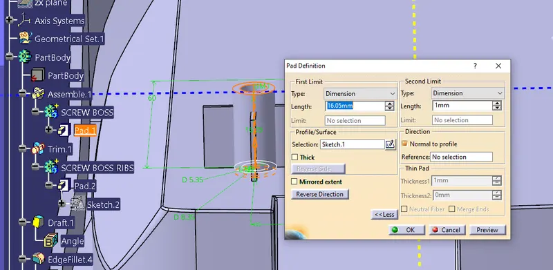
H = ' Screw Height ' ≤ 3*d = 3*5.35 = 16.05mm.
h = ' Coring inside dog house ' = 3<->6mm here we take 4mm.
MAIN TREE:
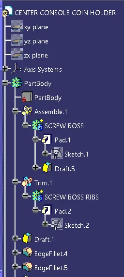
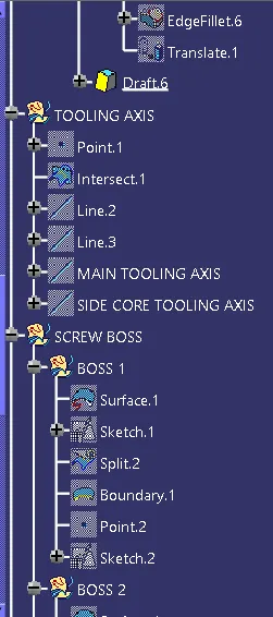
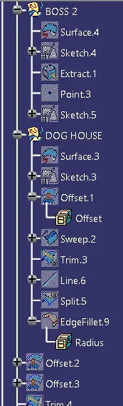
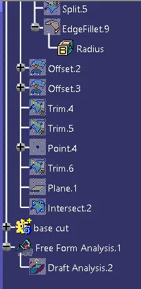
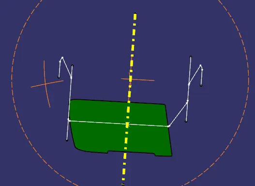
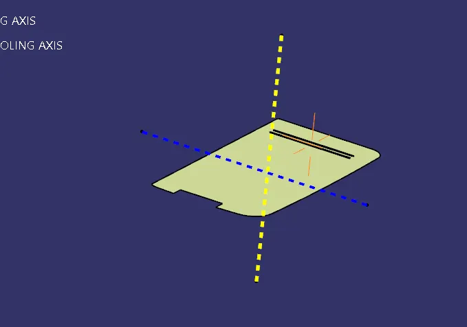
Create a Tooling Axis for the Class A surface.
TREE:
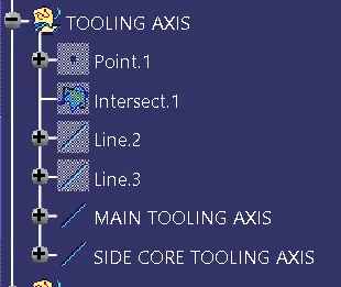
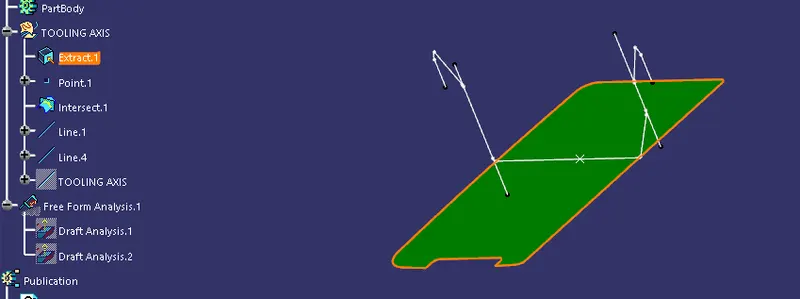
- Create a point on the class A surface to move the main tool for component creation on the base surface.
- Mask an axis over the point created with the same directions as the main axis
 .
. - Using Intersect command from Generative Shape design select the YZ plane as the first element and the class A surface as the second element
 .
. - After creating the intersecting lines select the Line command and join the vertices which show the most possible draft angle manufacturable.
- Bisect those two lines over the axis point we created
 .
. - Also for the side core create a line with the direction in the Z component for the side tooling axis with the point created in the first point.
OBJECTIVE 2: DRAFT ANALYSIS of Class A surface:
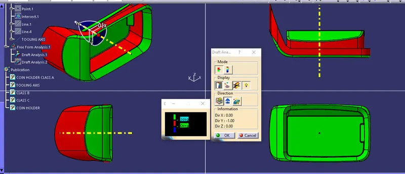
Note: Class A surface was constructed wrongly as there is no draft angle on the bin walls of the coin holder.
PROCEDURE:
- After Tooling Axis Select the Feature Draft Analysis option from the Insert Option
 .
. - Select the element to analyze.
- Next click on Use the compass to define the new current draft direction option and make it align with the tooling axis by dragging it to the axis
 .
. - If the color appears blue just click the invert option on the right side of the draft direction axis button.
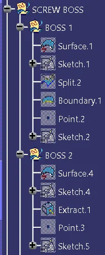
OBJECTIVE 3: Creating Screw Boss and Dog house on the base of the Coin Holder.
TREE:
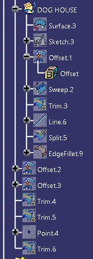
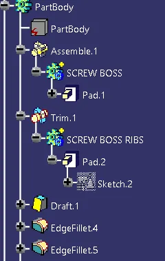
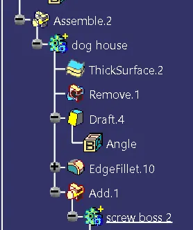
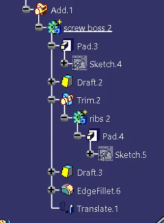
SKETCH and Creation in Generative shape design and Part design:
Extract the base surface and create a sketch on it.
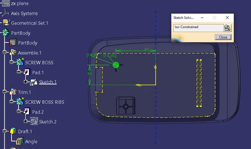
In Generative Shape Design, Extract the surface up to 16.05 mm as calculated.
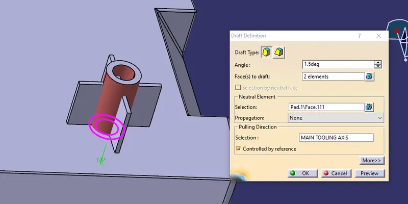
A draft angle of 0.5 as estimated is drafted both in and out of the holes.
Ribs are extracted as per the sketch.
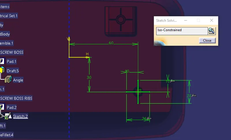
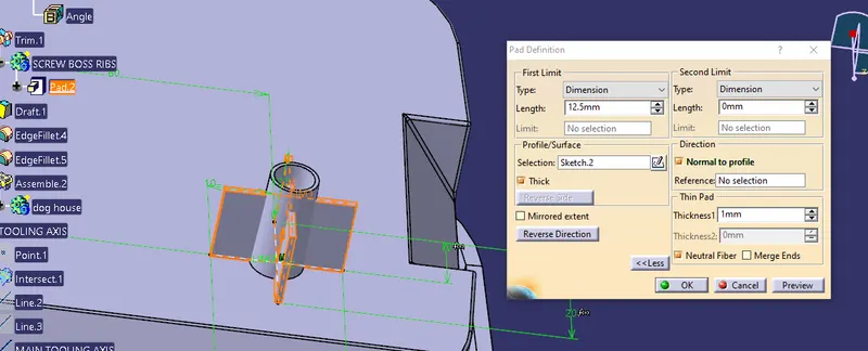
Note: Dimensions were given using the formula for variable changes if to be made for dog house with just changing one value while others change according to t the formula automatically.
The union trim command is used to trim it with the Screw head created.
A draft is given of value 0.5 degrees.
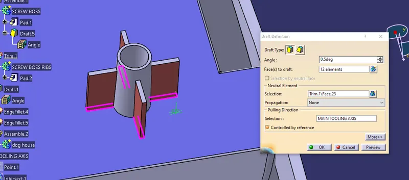
Fillets (0.25 mm) are given to all edges after assembling them to the main body.
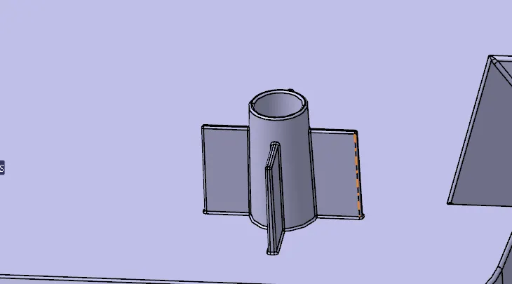
Similarly, another Screw boss is created in a new empty part body waiting to be translated.
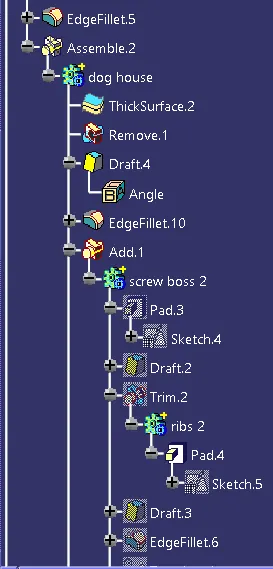
Dog House:
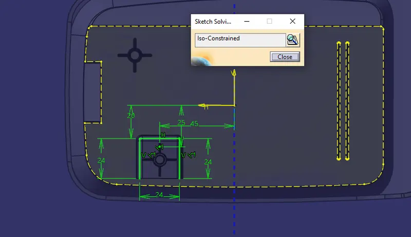
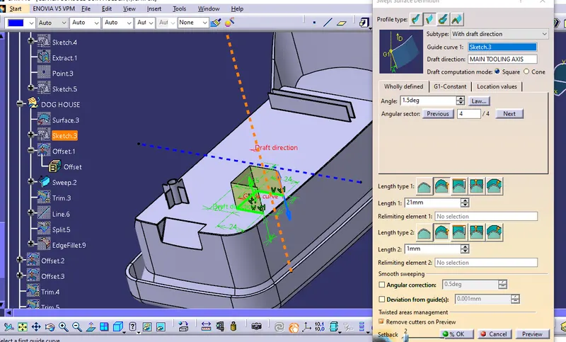
It is swept in the draft direction with 1.5 degrees.
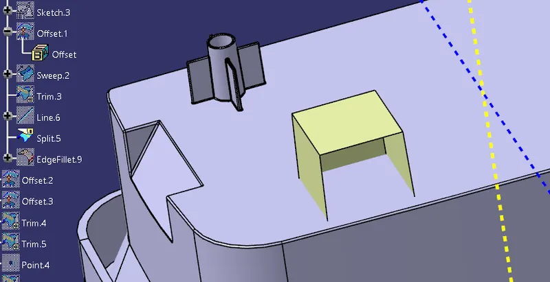
The base surface is offset and trimmed to form a cube with no front face.
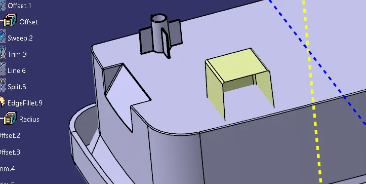
Fillets 1mm are given according to the height of the dog house.
A thick surface is given in Part design.
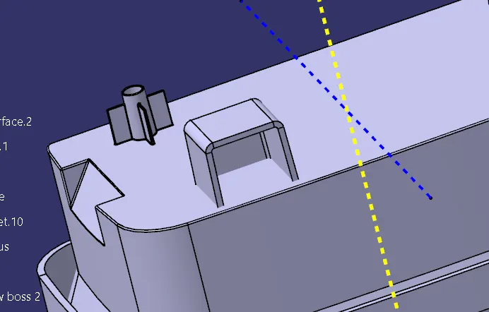
To create coring 1mm width and 4mm height is selected inside the dog house created.
Offset the base to 3mm and trim it with the original sweep to create a box, Using a thick surface give 1 mm outward extrusion, and using the remove command cut the part from the main dog house body.
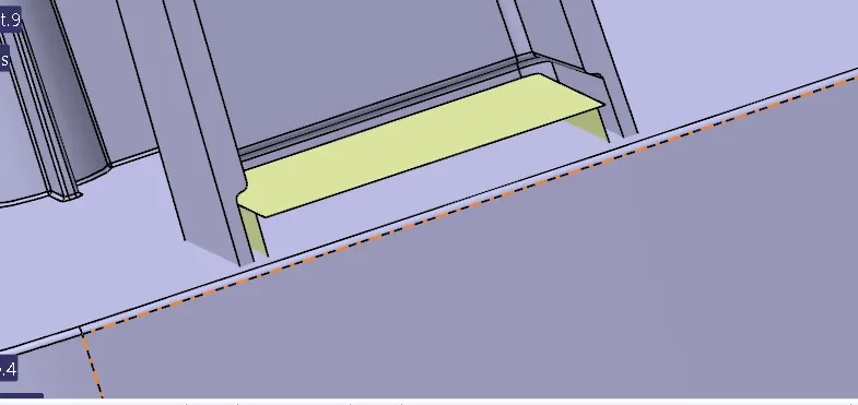
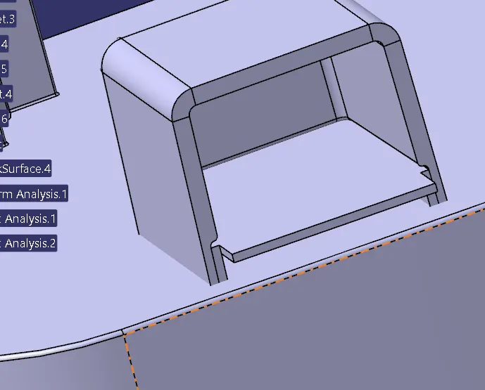
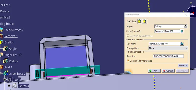
Using draft 1.5-degree draft the cutout part.
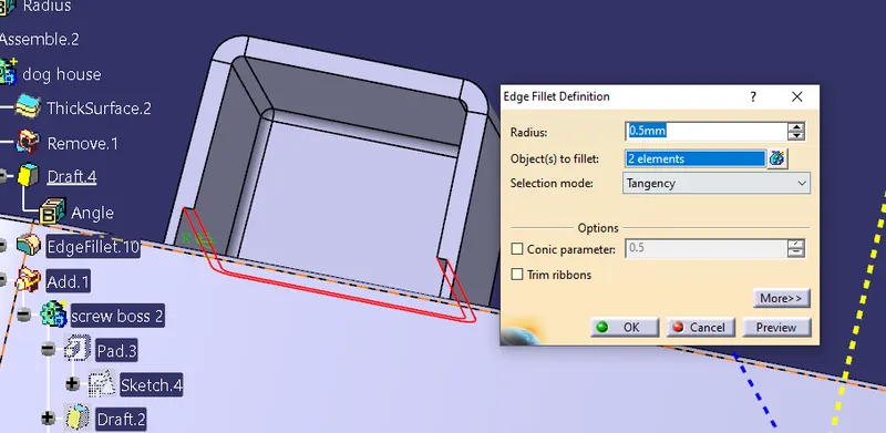
Give fillet f 0.5 degrees to both edges.
Using the translate command move the new screw boss to the top of the dog house with a point to point and add operation to add the parts.
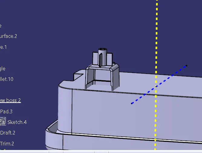
The final part with a dog house and screw boss features.
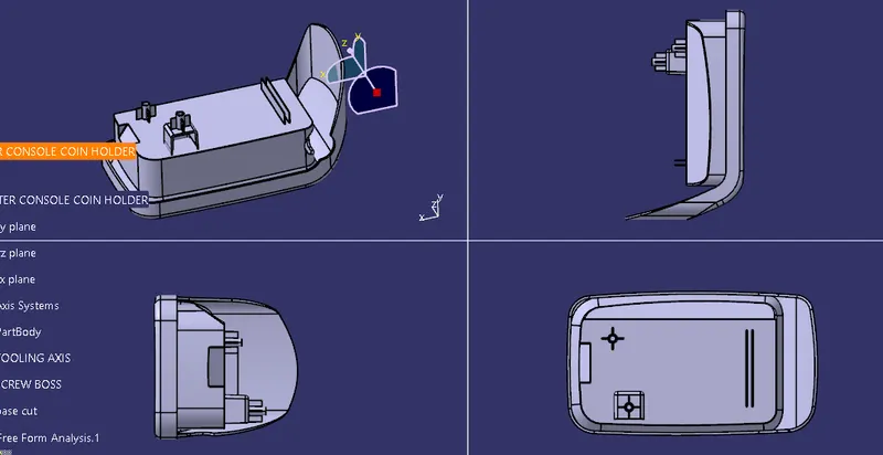
The intersection of the dog house with a screw boss on the main body.
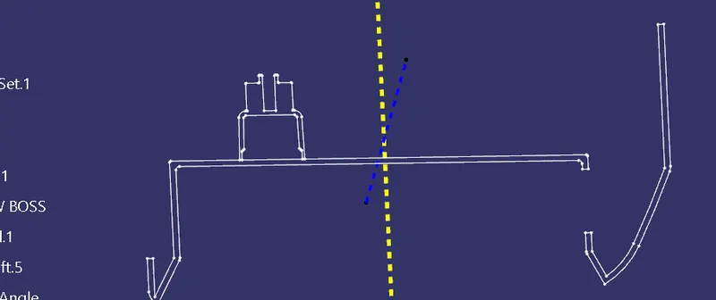
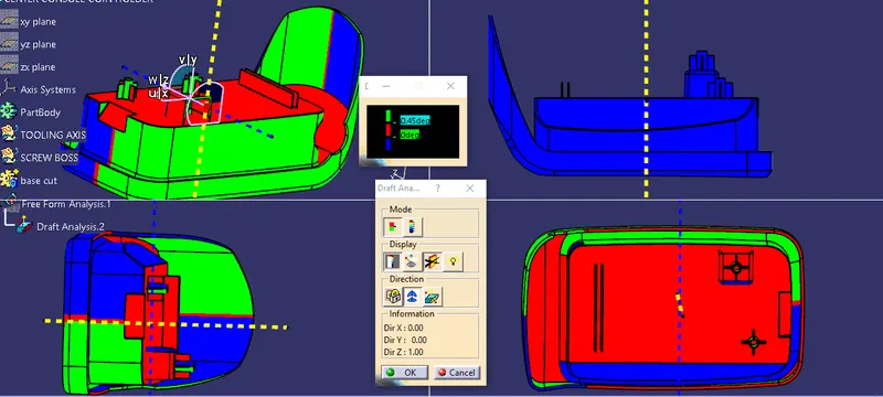
OBJECTIVE 4: Draft Analysis on Final component for both main tooling and side tooling.
PROCEDURE:
- After Tooling Axis Select the Feature Draft Analysis option from the Insert Option.
- Select the element to analyze.
- Next click on Use the compass to define the new current draft direction option and make it align with the tooling axis by dragging it to the axis.
- If the color appears blue just click the invert option on the right side of the draft direction axis button.
For the main tooling axis
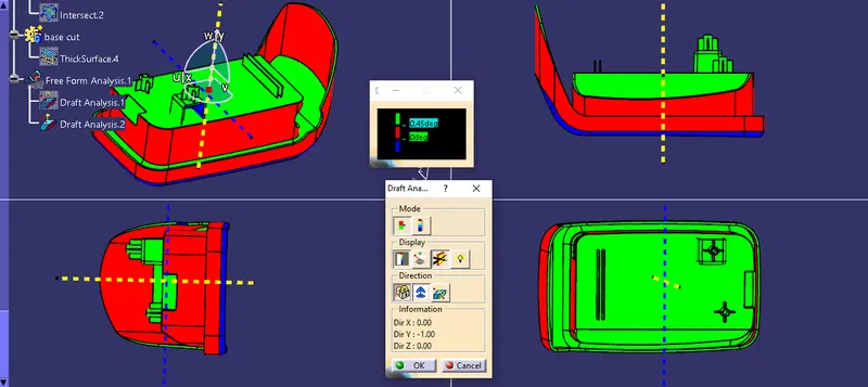
For Side Tooling Axis:
CONCLUSION:
Created Dog house and Screw boss on the base surface of the coin holder to add features(connectors to add to the main body part in the final assembly of all products), rigidity, and strength to the component with design rules as applicable.