Meshing of Door Inner Panel
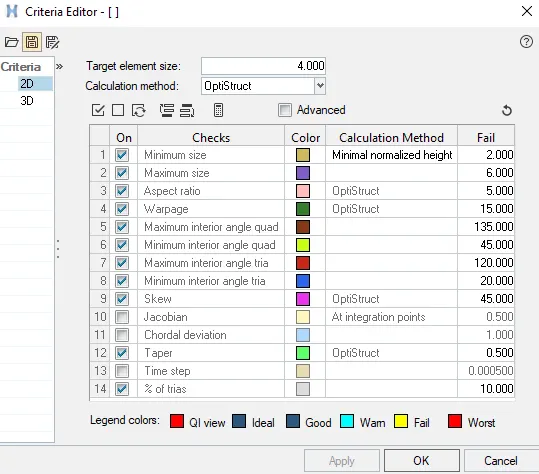
AIM - To mesh the door inner panel component following the element quality criteria shown below and to assign the required thickness to the component.
Target Element Length = 4 Units
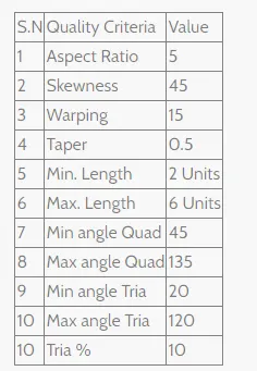
INTRODUCTION -
Door panels serve as an interface between the interior of the car and the inner workings of the door, and between vehicle occupants and the door. They are expected to meet a variety of design specifications regarding safety, aesthetics, and functionality. In addition, they are expected to continue the material theme of the dashboard and pillars while concealing intricate electrical and mechanical components for operating locks, windows, and other features.
The door panel will usually match the rest of the vehicle's interior. Door panels were formerly made of cardboard with an upholstered interior finish of vinyl, leather, cloth, carpet, or other materials for the decorative trim. Modern cars typically have door cards made of plastic, most often using injection molding, as well as incorporating other decorative materials.
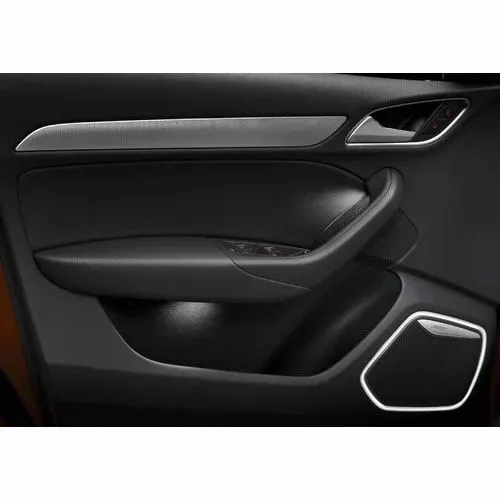
Here as we know the door inner panel is a plastic component. so the meshing will be plastic meshing. Plastic meshing is a type of shell meshing where the thickness of the component varies. In plastic meshing, the mid-surface extraction plays a vital role. Because the thickness of the component varies auto mid surface cannot be used. So we have to go for manual mid surfacing.
ELEMENT QUALITY CRITERIA:
In this project, an inner door trim is given with all design criteria satisfied and clear to generate mesh for post-analysis. For element quality check-in hypermesh we verify the basic quality of elements and the geometric qualities of those elements.
Warpage: It is the amount by which an element (or in the case of solid elements, an element face) deviates from being planar. This check is only applicable to quads as three nodes define a plane that does not define any deviation.
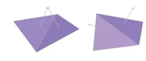
To solve this issue, check which side needs to be made planar to the other three nodes so that the element can be released from warpage then use the translate command to make the nodes in planar form.
Aspect Ratio: This is the ratio of the longest edge of an element to either its shortest edge or the shortest distance from a corner node to the opposing edge.
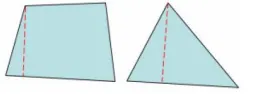
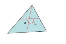
The skew of triangular elements is calculated by finding the minimum angle between the vector from each node to the opposing mid-side, and the vector between the two adjacent mid-sides at each node of the element.
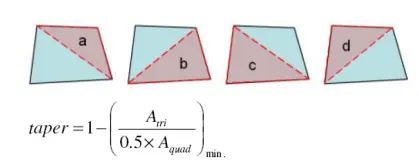
The taper ratio for the quadrilateral element is defined by first finding the area of the triangle formed at each corner grid point. These areas are then compared to one-half of the area of the quadrilateral.
Minimum and maximum interior angles: Interior Angles with maximum and minimum values
are evaluated independently for triangles and quadrilaterals.
PROCEDURE:
Given Inner door trim panel design is as shown below:
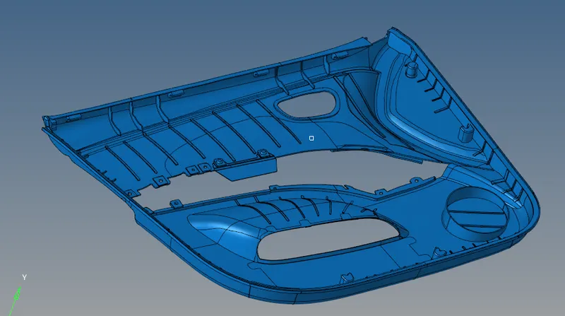
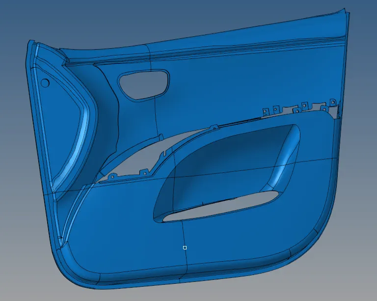
To generate the mesh for the above-mentioned component following steps were followed.
- Delete any solid components and use the auto mid surface command to generate a mid surface for the component.
- For the geometry cleanup use the various commands from the quick edit option such as surface split, washer split, toggle edges, etc.
- Use 2D auto mesh to slowly start mesh of the component by selecting small split surfaces.
- Maintain a proper mesh flow with lower tria concentration, at corners or curving portions of the body tries can be kept to maintain the element quality criteria.
Once geometry cleanup is completed (e.g. surfaces are stitched together — no unwanted free surface edges inside the geometry), meshing is next.
Things to keep in mind while doing meshing:
- The mesh should look rather smooth and regular as the analysis is based on the mesh quality.
- Try to Keep mesh-related uncertainties to a minimum if possible.
- Remove any opposite tria elements wherever possible.
- Avoid Rotating Quads and prefer tria in their place.
- Don't let the mesh distort or move beyond the surface integrity.
- Near corner or converge/diverge regions try to keep the mesh with tria smooth as possible.
- First, import the geometry as a door inner panel component and split the body into 4 parts along the axis and a base point such that it is easier to extract mid surface manually.
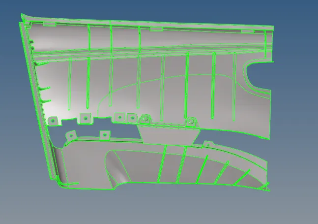
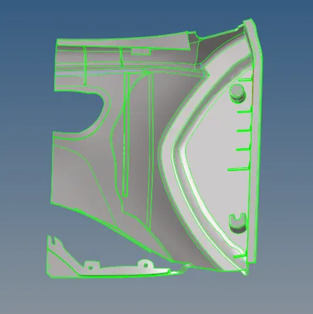
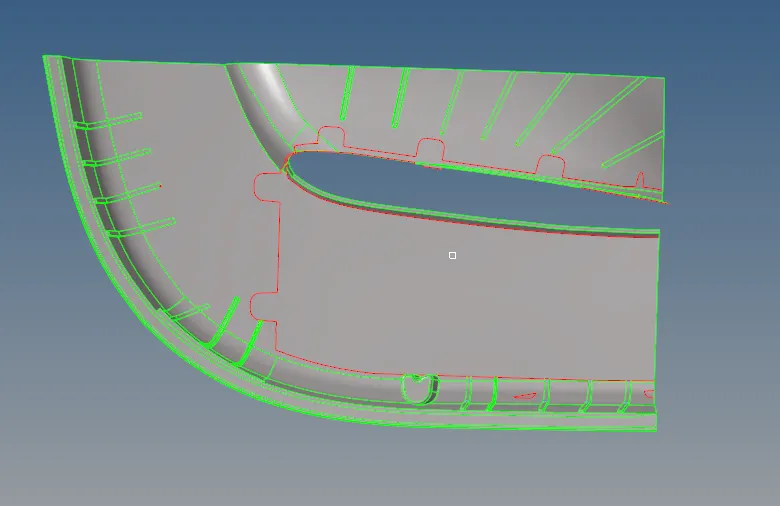
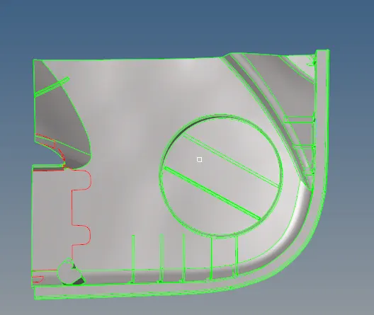
Now for manually extracting the mid surface use the surface offset command and duplicate it to a new component according to the thickness of the component which is varying in several areas. But before that, there are several fillets that need to be de-featured as they create errors while extracting mid-surface.
First, the lower right half portion of the door inner panel is used for extracting the mid surface and meshing it. The component after defeature is shown below:
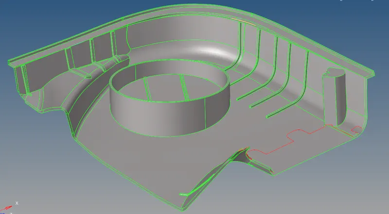
Then using the Offset command from surface edit extract the manual mid surface of the component by offsetting the surfaces at the center.
Used the surface pair option to extract the mid surface of the ribs.
The extracted mid surface should be extended to the bottom base surface using the extend option in surface edit. The mid surface of the component is shown below:
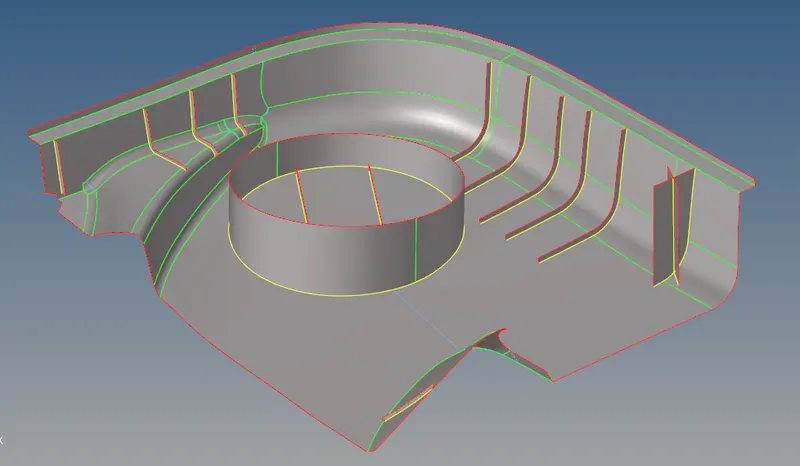
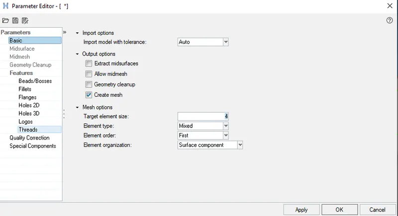
Now For meshing, use the batch meshing under the auto mesh. But before meshing, create a parameter file and criteria file as the mesh needs to be according to the element quality criteria given. The criteria file and parameter file are shown below:
The mesh of the component is shown below:
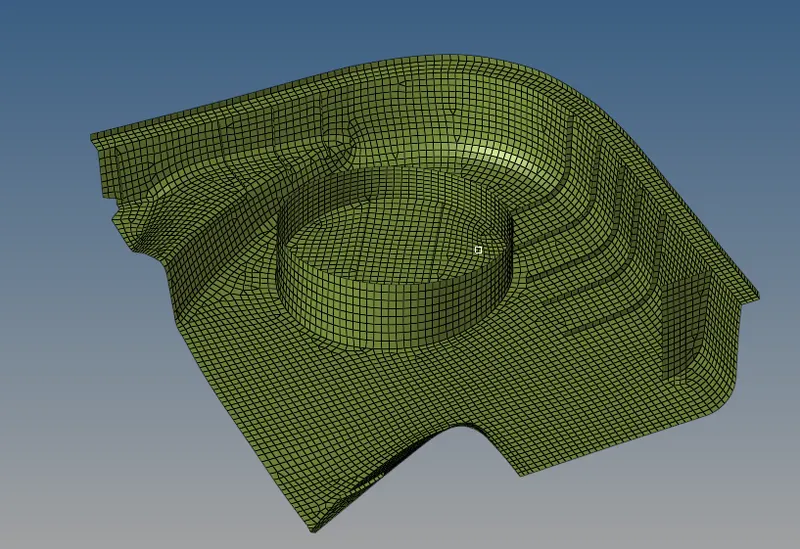
After the meshing is done check for the element failures. For rectifying the element failures use the following commands.
- Drag tria command under the quality index
- Remesh the elements for clearing the element failures
- Element optimization under the quality index
- place node command under the quality index
- Translate command to translate nodes. This command will be under the tool section
- smooth command which will smooth the mesh and ultimately remove the element failures
- Element edit command to split, create and combine elements.
The final mesh of the lower right half of the door inner panel free from any element failures is shown below:
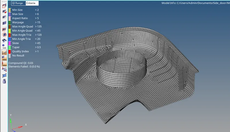
Similarly for all the other parts, we created the same procedure is followed.
Lower Left part:
Parent body after defeaturing
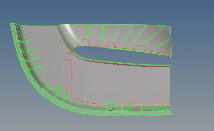
The mid surface is extracted manually and all the ribs and locators are trimmed to the main body.
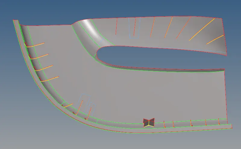
The batch mesh of the component is as below.
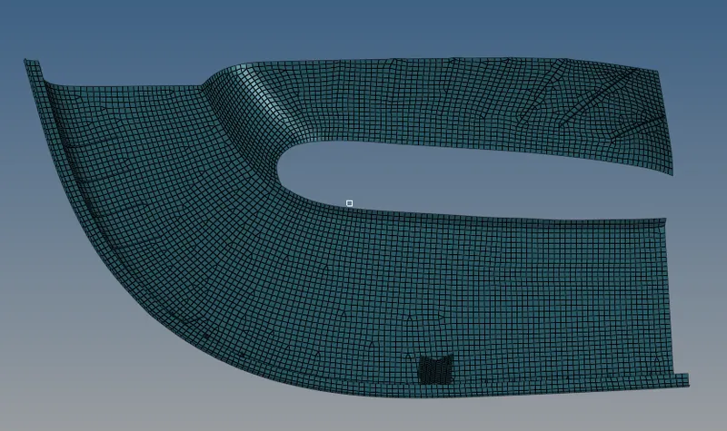
After all the required element cleanup is done.
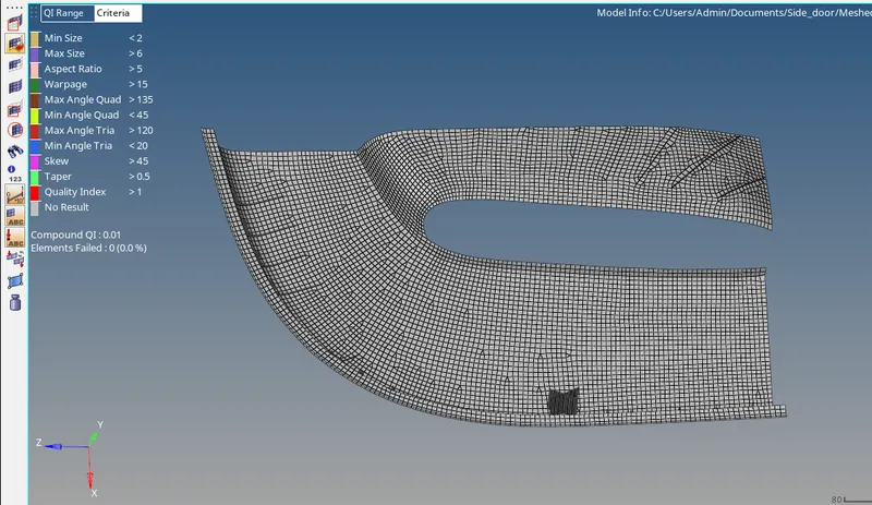
Upper Right Part
The parent geometry after defeaturing is shown below:
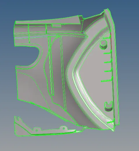
The mid surface of the component is shown below:
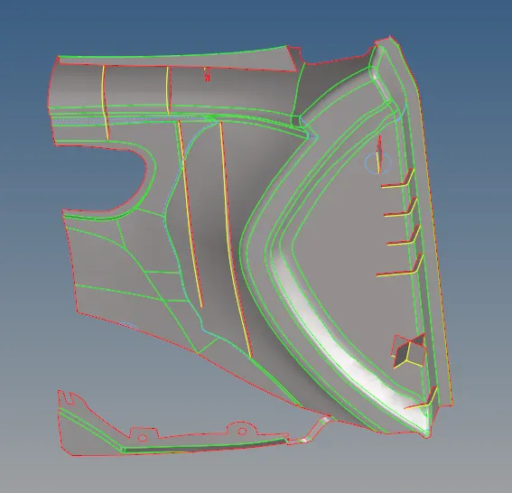
Mesh the component using the batch mesh under the auto mesh panel under the 2 D section. The mesh of the component is shown below:
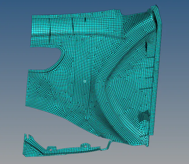
After all the required element cleanup is done.
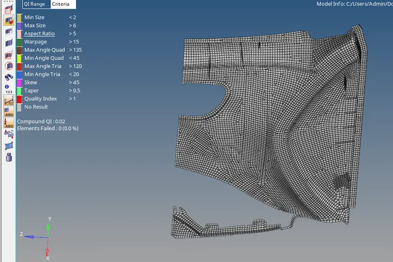
Upper Left
The parent body after defeaturing is shown below:
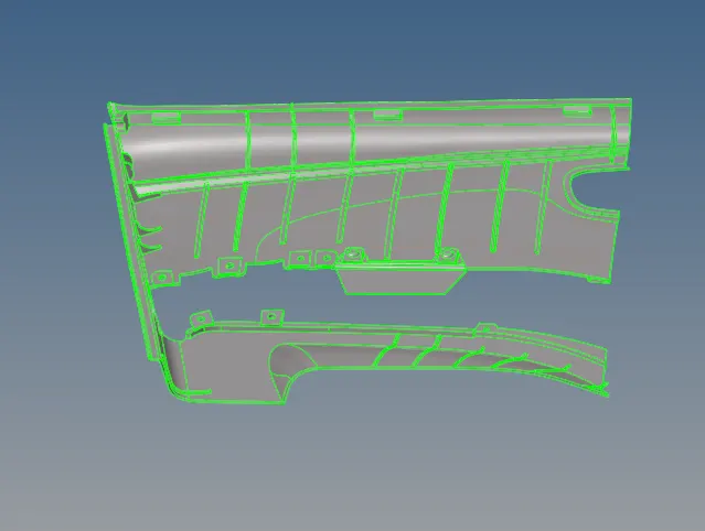
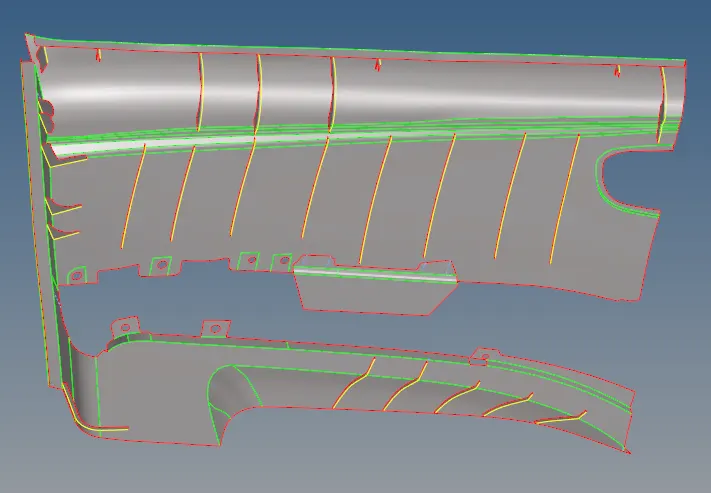
The mid surface extracted manually after defeaturing the geometry is shown below:
Mesh the component using the batch mesh under the auto mesh panel under the 2 D section. The mesh of the component is shown below:
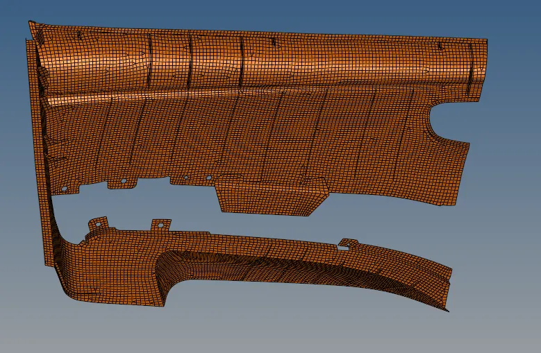
After all the required element cleanup is done.
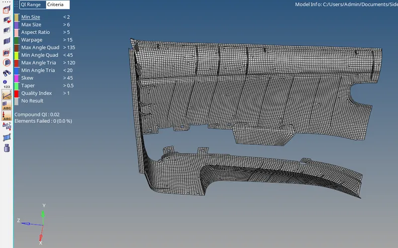
Now meshing of individual components is done and now keep all the elements and all the components that we split earlier in a single component. Here one thing one has to ensure is the connectivity of all the elements in one component. The mesh of all the components combined free from element failures is shown below:
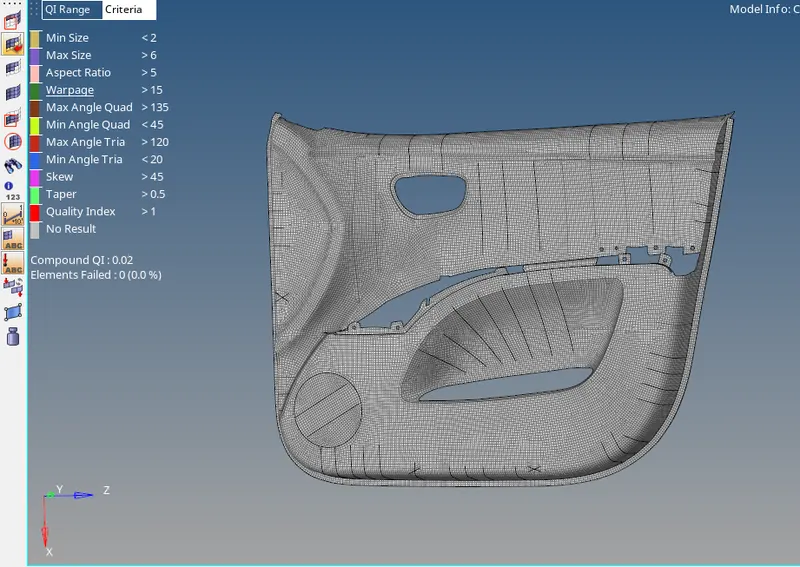
Now assign the thickness to the component. So for that, use the auto thickness method, go to the mesh menu on the top then assign then will click on mid mesh thickness a map mid mesh thickness window will pop up as shown below:
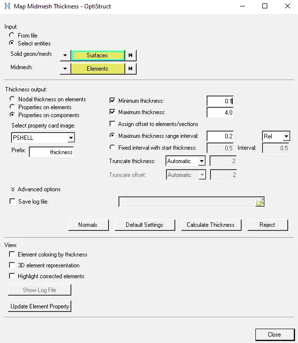
Here as we can see it is asking for surfaces and elements. so select all the surfaces of the parent body and all the elements that are in one component. Then finally click on calculate thickness. HyperMesh will generate the automatic thickness for the component. The thickened component is shown below:
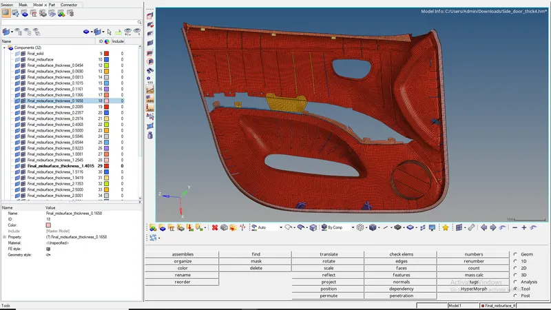
RESULT - The mesh of the door inner panel after assigning the thickness is shown below:
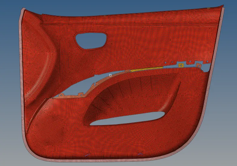
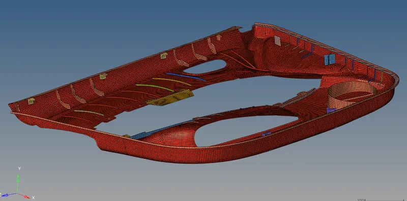
CONCLUSION - The meshing of the door inner panel has been completed successfully and the thickness was also assigned to the mesh.