Photo Realistic Rendering
DESIGN OF AMERICAN CHOPPER USING SOLIDWORKS
OBJECTIVE
The objective is to model an AMERICAN CHOPPER using SolidWorks and render the same in SOLIDWORKS visualize to create a realistic view.
INTRODUCTION
This project explains the design of the American chopper using SOLIDWORKS from sketching the parts and modeling them to the final rendering of the assembly to give a photo-realistic view.
METHODOLOGY
- Part Modelling
- Assembly
- Rendering
FLOW CHART
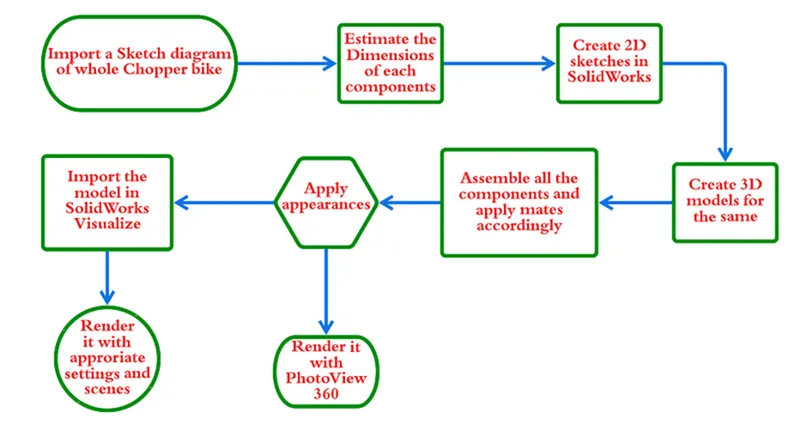
PART MODELING
In part modeling, first, the 2D sketch of the part is sketched using the tools in the sketch tab and then the 2D sketch is converted into a 3D part using features in the features tab.
FEATURES USED
- Boss Extrude: Used to expand the object in 3D according to sketch plane.
- Extrude Cut: Used to cut/remove the 3d object in linear according to the sketch.
- Fillet: used for making round internal or external edges to avoid sharp edges and make them smooth.
- Lofted Boss/Base: Used to achieve Complex Shapes. It does this by interpolating surfaces between various cross-sections of a model. These cross-sections can be sketches, faces, or edges.
- Dome: Used to make dome-shaped extrude including the elliptical dome.
- Shell: Used to make hollow space in solid part by selecting the outer wall of the solid part and so removing the inner parts. It is also used to reduce the specific thickness.
- Chamfer: Used to make a sharp edge or corner slightly tapered rather than being a perfect square.
- Linear Pattern: Used to create a different number of instances required to create the pattern linearly.
- Curve Driven Pattern: Used to make any pattern followed by the curve sketched before.
- Circular pattern: Used to make 3d features into a circular pattern according to a number of insistences.
- Revolve boss base: Used to make cylindrical or circular 3D extrude along with a given reference axis as per drawn sketch.
- Revolve cut: Used to cut or reduce the extrude of the cylindrical round surface.
- Split: Used to split a single solid part into two solid parts. It is used to project an entity onto other surfaces or curved/planar faces.
- Move/copy body: Used to move/copy the 3D body from one place to another place.
- Mirror: Used to mirror a feature or body by reference to the selected plane.
- Sweep: Used to sweep any kind of fully defined sketch along with the path.
- Sweep cut: Used to make a cut along with the sweep path.
- Swept Surface: Used to make a surface along with a path the curve is driven.
- Combine: Used to make integrate two solid parts which intersect each other as the same solid part.
- Boundary Surface: Used to make a surface in between two finished surfaces.
- Loft Surface: Used to make a loft in between two profiles along with a guide path.
- Knit surface: Used to knit the two free edges or open edges of the surfaces together also it reduces the gap between the two edges of the surface.
- Surface Trim: Used to cut away material from a surface, and provides two modes: Standard and Mutual.
- Projection Curve: Used to project two different 2D curves in two different planes into a single curve.
- Appearances: An appearance defines the visual properties of the model including color and texture. Appearances do not affect physical properties which are defined by materials. every material is assigned a default appearance.
ASSEMBLY
You can build complex assemblies consisting of many components, which can be parts or other assemblies, called subassemblies. For most operations, the behavior of components is the same for both types. Changes in the component are automatically reflected in the assembly i.e. The rebuild option will automatically take place or else it will ask the user to rebuild the document.
RENDERING
Rendering is the process of adding shading, color, and lamination to a 2-D or 3-D wireframe in order to create life-like images on a screen.
SOLIDWORKS Visualize and PhotoView360 are photo-realistic rendering tools that utilize your CAD data to create magazine-quality images or commercial-quality animations.
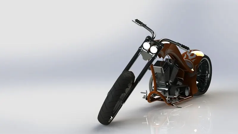
COMPONENTS DESIGNED
- Transmission Belt
- Kick Stand
- Front Fender
- Rear Fender
- Chain
- Oil Tank
- Pedal
- Front Wheel
- Rear Wheel
- Front Fork
- Chassis
- Engine
- Gas Tank
TRANSMISSION BELT
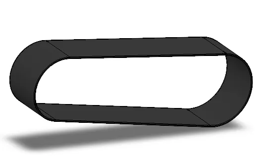
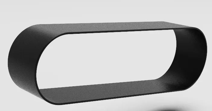
Features used
- Offset entities
- Extrude boss
- Fillet
- Appearances
KICKSTAND
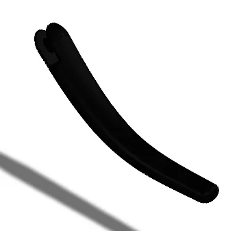
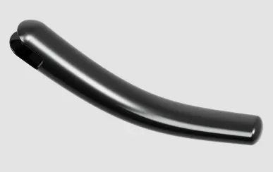
Feature used
- Loft boss
- Extrude boss
- Extrude cut
- Dome
- Split
- Fillets
- appearance
FRONT FENDER
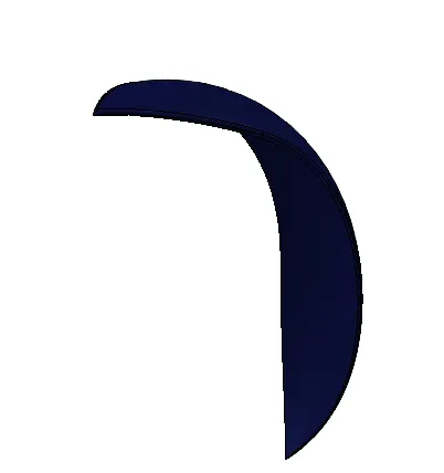
Features used
- Offset entities
- Trim entities
- Revolve boss
- Dynamic Mirror
- Split
- Appearances
REAR FENDER
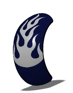
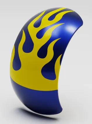
Features used
- Offset Entities
- Trim Entities
- Revolve boss
- Appearances
CHAIN
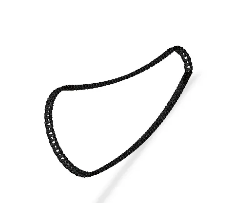
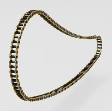
Features used
- Trim entities
- Fillet
- Blocks
- Extrude boss
- Linear Patterns
- Appearances
OIL TANK
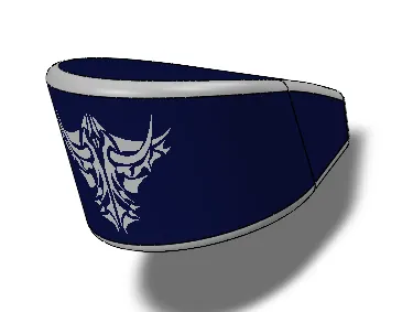
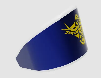
Features used
- Boss Extrude
- Combine
- Fillet
- Shell
- Appearance
PEDAL
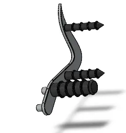
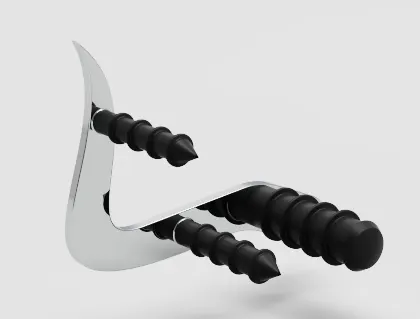
Features used
- Extrude boss
- Fillet
- Linear pattern
- Dome
- Chamfer
- Appearance
FRONT WHEEL
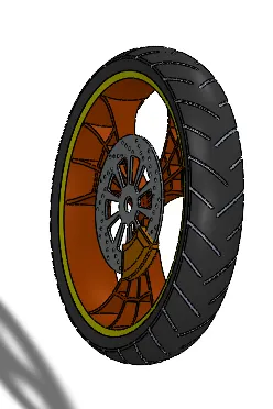
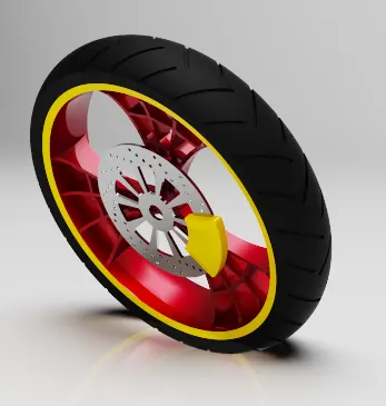
Features used
- Revolve boss
- Trim entities
- sketch fillet
- Boss Extrude
- Revolve Cut
- Linear Pattern
- Chamfer
- Cut Extrude
- Circular Pattern
- Appearance
REAR WHEEL
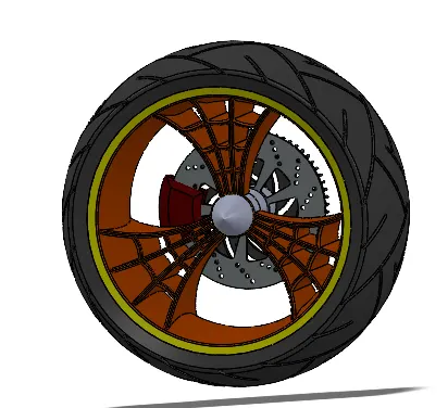
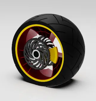
Features used
- Revolve boss
- Trim entities
- Fillet
- Extrude Boss
- Planes
- Revolve cut
- Linear pattern
- Chamfer
- Fillet feature
- Extrude Cut
- Circular pattern
- Appearance
FRONT FORK
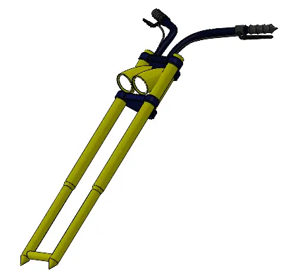
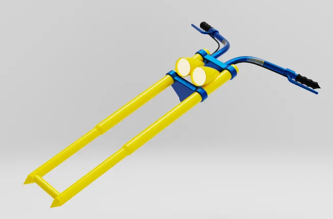
Features used
- Extrude boss
- Trim entities
- Revolve boss
- Split
- Move/copy bodies
- Dome
- Mirror
- Combine
- Projected curve
- Sweep boss
- Appearance
CHASSIS
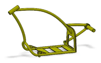
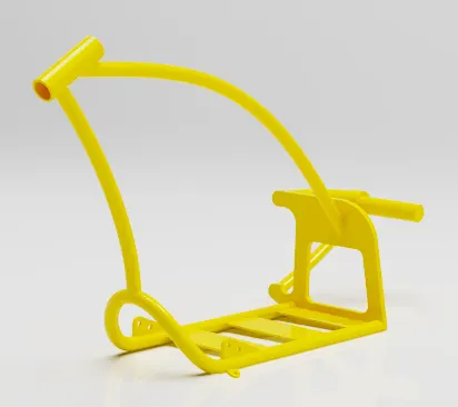
Features used
- Offset entities
- Convert Entities
- Project Curve
- Trim entities
- Sweep boss
- Split
- Revolve Cut
- Extrude boss
- Fillet
- Combine
- Appearance
ENGINE
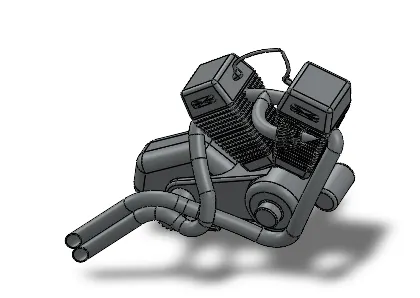
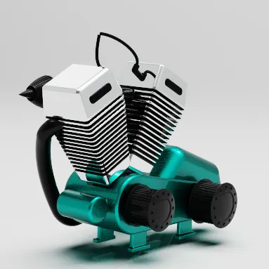
Features used
- Trim entities
- Revolve Boss
- Extrude Cut
- Offset entities
- Dome
- Fillet
- Projected Curve
- Composite Curve
- Sweep boss
- Mirror
- Circular pattern
- Split
- Appearance
GAS TANK
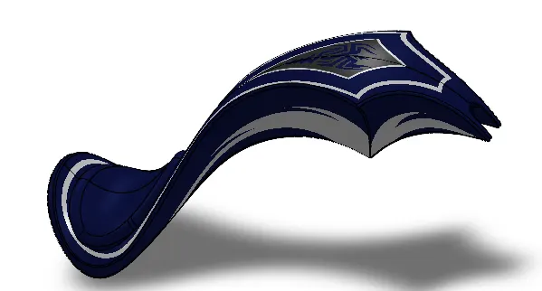
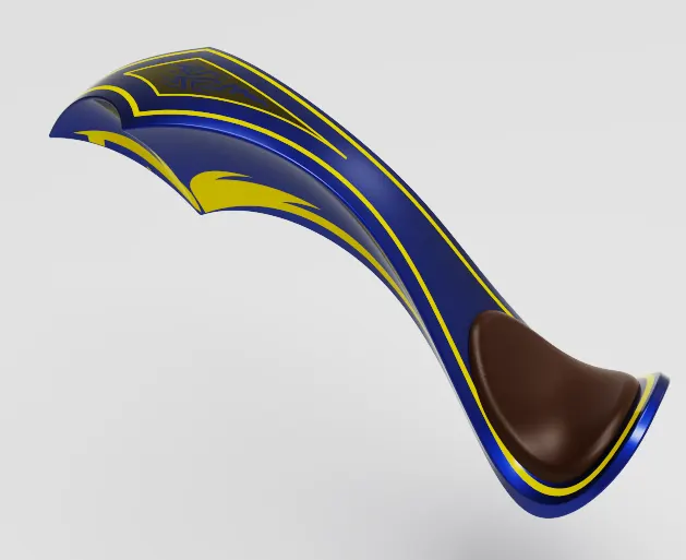
Features Used
- Projected curve
- Trim entities
- Sweep boss
- Loft surface
- Knit surface
- Sweep Cut
- Fillet
- Appearance
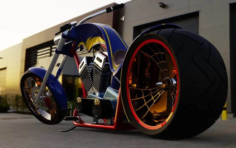
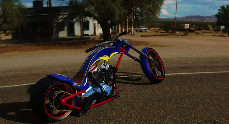
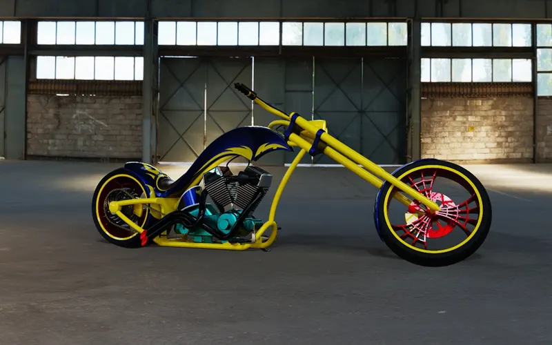
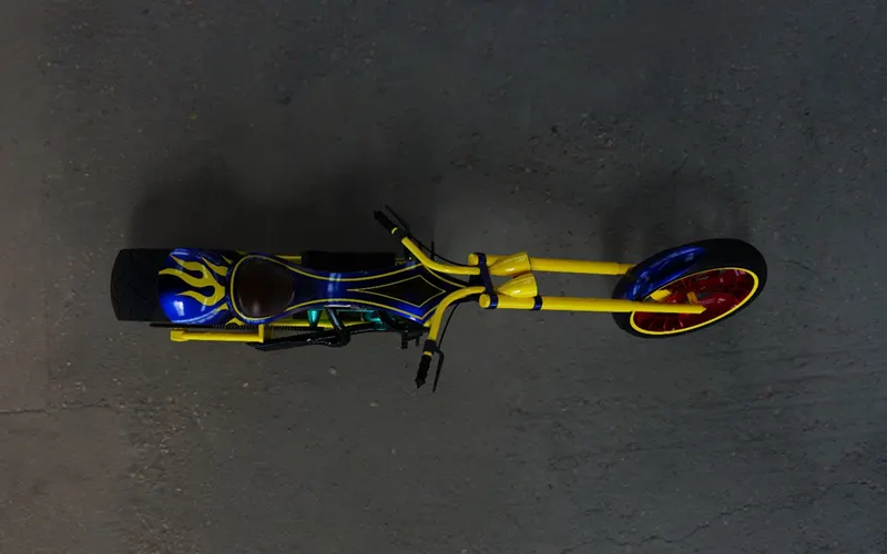
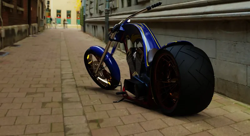
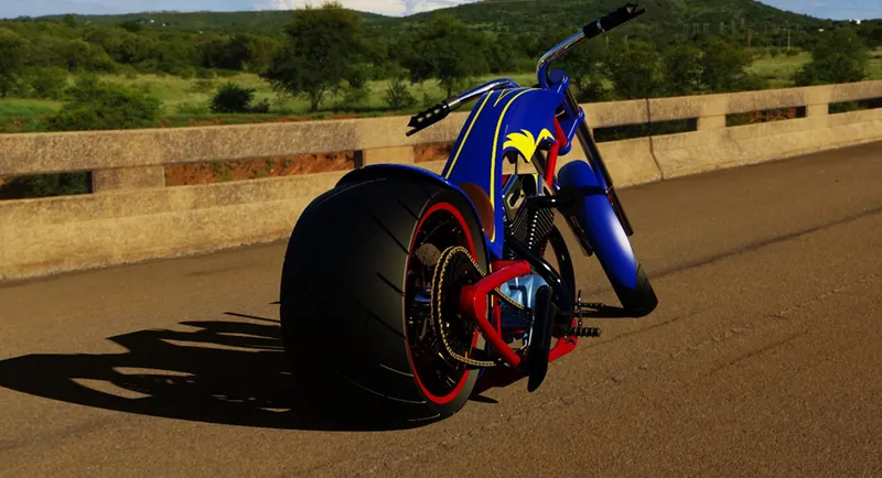
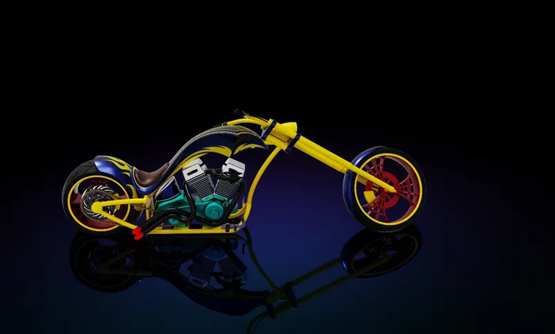
FINAL RENDERS OF AMERICAN CHOPPER
CONCLUSION
All the components were designed assembled & rendered in SolidWorks and Solidworks Visualize according to the sketch images.