Week - 4
AIM:
A) Implement control logic of a “washing machine” using Stateflow as per given sequence:
1. If the power supply is available, the system gets activated
2. If the Water supply is not available, stop the process & indicate through LED
3. Soaking time should be 200s followed by Washing time of 100s.
4. Then rinsing happens for the next 20s & dryer runs for 50s
5. After all the processes have completed turn on the finished LED
B) Make a Simulink chart for the “Gear shift” logic as per the below conditions:
Speed Range(kmph) Gear
0 to 15 1
16 to 25 2
26 to 40 3
41 to 60 4
Above 61 5
Give speed input while the simulation is running & display the gear number.
Solution:
Control Logic:
Control logic is the part of a controller that defines how a reactive system responds to events or conditional changes.
PART A)
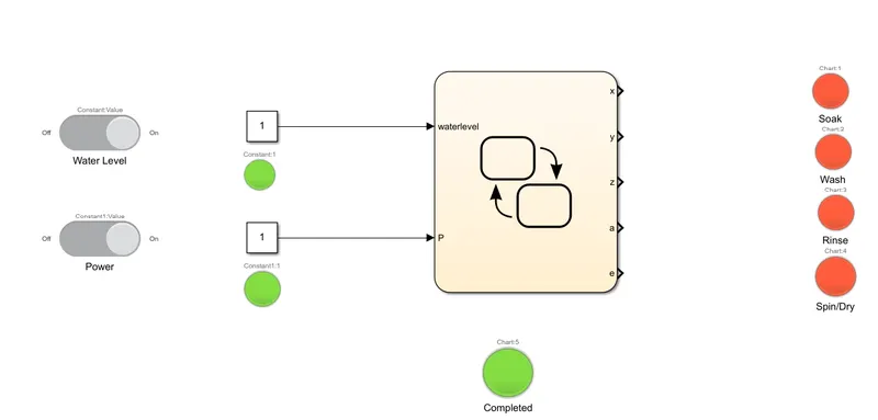
In a washing machine, there are 4 processes Soak, Wash, Rinse, Spin/Dry. For the given conditions Our Washing machine must soak for 200 sec, Wash for 100 sec, Rinse for 20 sec, Spin/Dry for 50 sec.
But also if there is no water supply the process must stop, and at no power the washing should not switch on.
To achieve this we use the following blocks and a state flow chart:
- Lamps
- Constants
- Slider switchs
- State flow charts
State Flow chart:
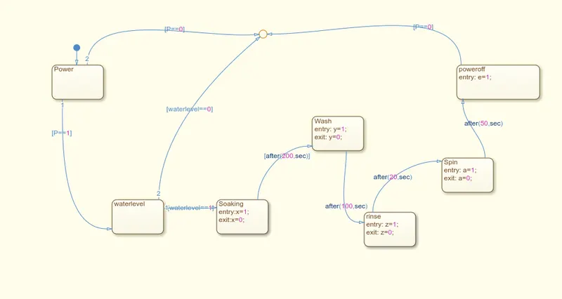
Here for power On two conditions are checked, if p==0 and p==1 which basically determines if the slider switch is on/off same goes for water level, if either of them do not satisfy the conditions then the system is turned down.
Soaking occurs for 200 sec so the condition to continue into washing process after(200,sec) is used. For lighting the lamp during soaking process at entry: x=1; parameter is used and so on for wash, rinse ,spin the parameters y, z, a are used with time interval 100, 20, 50sec respectively.
Simulink block:
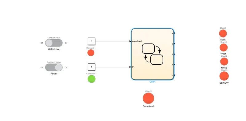
Condition 1: Power is off and water supply is off then system does not turn on
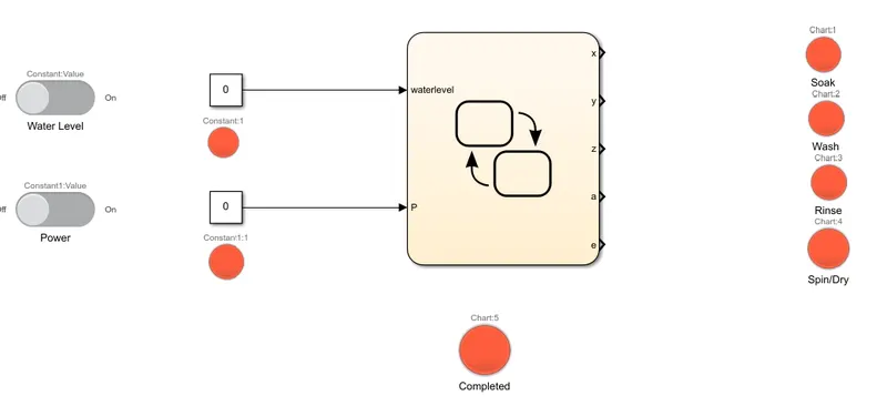
Condition 2: Power is on and water supply is off then also system doesn't turn on.
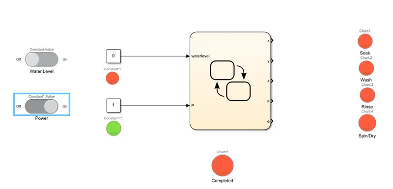
Condtion 3: Soak for 200sec
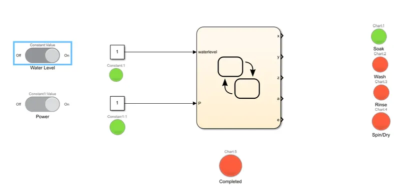
Condtion 4: Wash for 100 sec
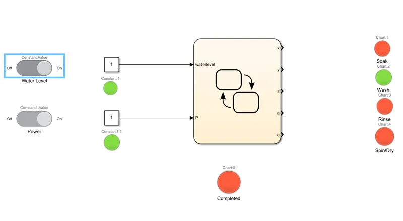
Condition 5: Rinse for 20sec
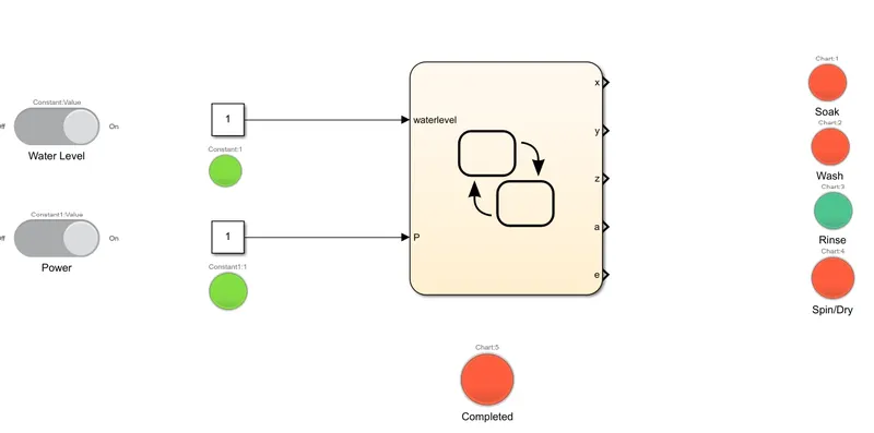
Condition 6: Spin/ Dry for 50 sec.
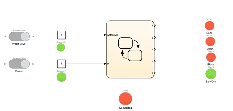
Condition 7: All process done and completed signal should be given.
PART B) Simulink chart for gear shifting according to the speed input.
Conditions are to change gears after a certain speed limit is crossed.
Speed Range(kmph) Gear
0 to 15 1
16 to 25 2
26 to 40 3
41 to 60 4
Above 61 5
Blocks used:
1. Constant
2. Slider
3. Display
4. state flow chart
State flow chart is as follows:
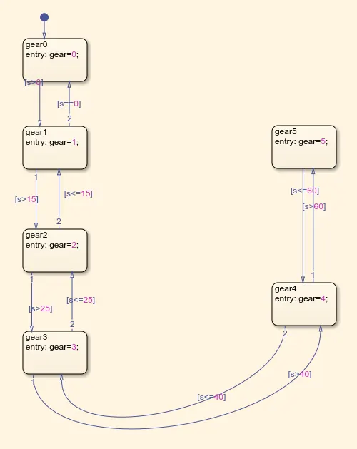
here if speed is greater than 15 then gear changes to 1, is s greater than 25 then gear changes to 3 and so on for gear 4 and 5 is checked.
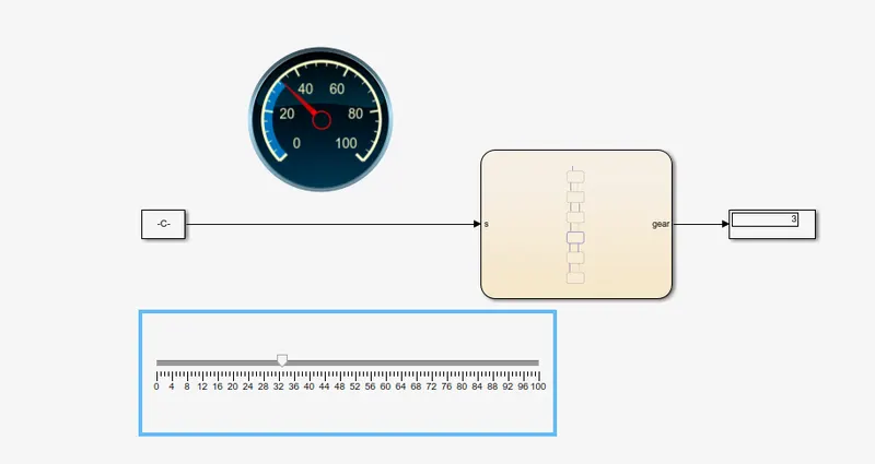
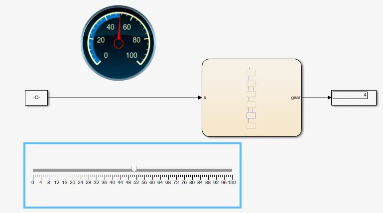
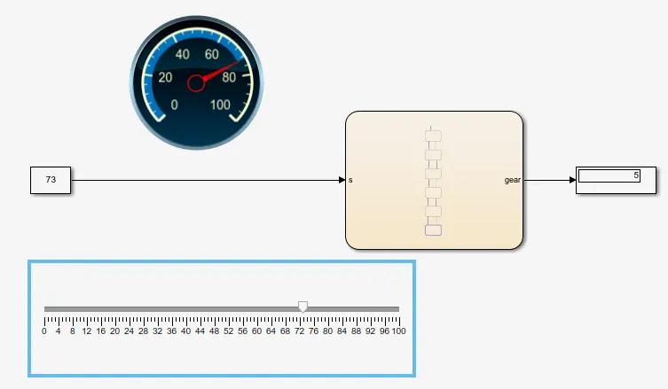
Simulink block for gear shift logic
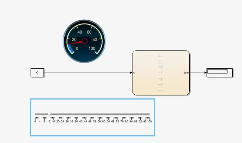
Condition 1: Speed greater than 0 and less than 15
 \
\
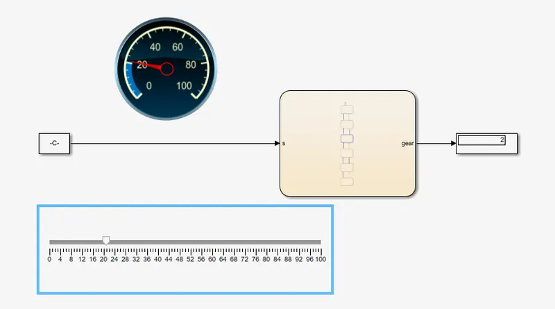
Condition 2: Speed greater than 15 and less than 25
Condition 3: Speed greater than 25 and less than 40
Condition 4: Speed greater than 40 and less than 60
Condition 4: Speed greater than 60
Animation for gear box change while speed change:
Link for washing machine Simulink block
Link for Gear shifter Simulink block