Week 8 - Challenge 5 - Core & Cavity Design
AIM: Create the Core and cavity blocks for the switch bezel.
Parting Surface:
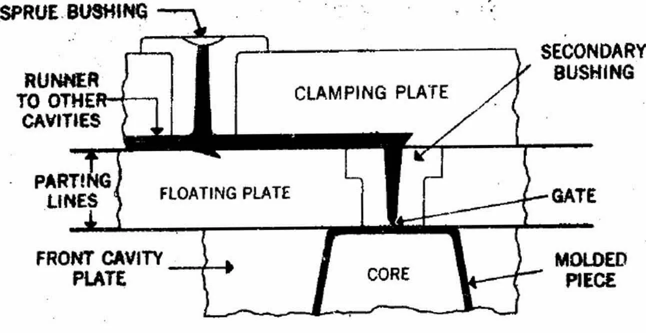
The parting surface of a mould are those surfaces of both mould plates adjacent to the impressions which butt together to form a seal and prevent the loss of plastic material from the impression.
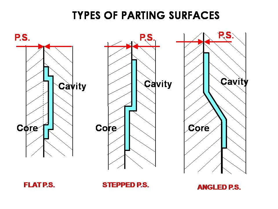
Design parting surface should follow the following principles:
- Design the injection mold structure as simple as possible. Avoid or reduce side parting as much as
possible to reduce the complexity of mold making. - Ease of de-molding. As far as possible, for instance, the plastic parts should stay in fixed halve of the
injection mold and ejected by ejection system, avoid side de-molding action. - Ensure the dimensional accuracy of the molded parts. Try to make the parts with similar
dimensional accuracy requirements in the same module to reduce manufacturing and assembly
errors. - Ensure appearance requirement of the molded parts. Flash or mismatch occurs usually on parting
surface, so the parting surface should not be designed on any high quality requirement surfaces. - Ensure adequate venting. If possible, parting surface should be place at the end of the mold flow.
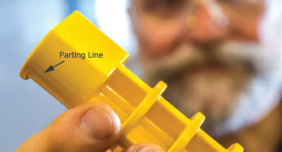
Parting line:
A parting line, in industrial casting of molds, is the border line in which draft angles change direction. That is, it is the dividing line that splits the core and cavity halves of a molded part. It is sometimes a starting point for the mold parting surface.
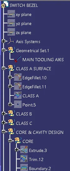
MAIN TREE:
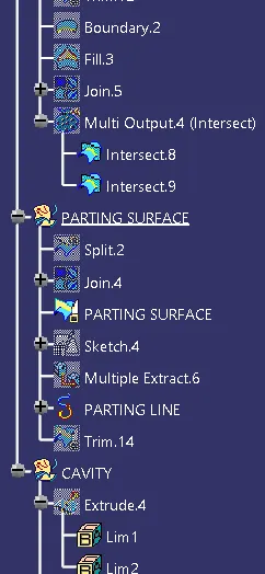
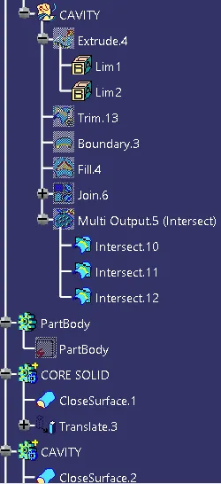
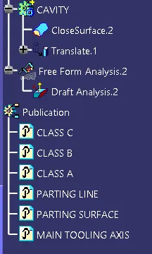
OBJECTIVE 1: Create a Tooling Axis for the Class A surface. (NOTE: Tooling Axis was already created)
TREE:
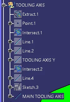
Procedure:
- Create a point on class A surface with the aim to move the main tool for component creation on the base surface.
- Mask an axis over the point created with the same directions as the main axis
 .
. - Using Intersect command from Generative Shape design select the YZ plane as the first element and the class A surface as the second element
 .
. - After creating the intersecting lines select the Line command and join the vertices which show the most possible draft angle manufacturable.
- Similarly, select the second axis and create intersecting lines but since only one side is available create a sketch of a line for the intersecting surfaces and make the draft line at an angle of 3 degrees.
- Bisect those two lines over the axis point we created
 .
.
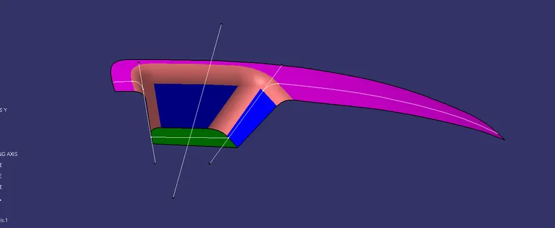
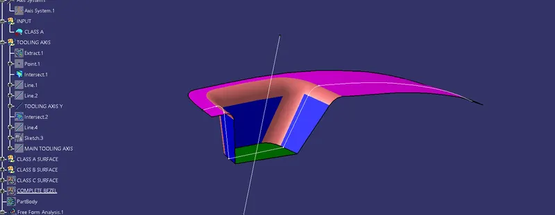
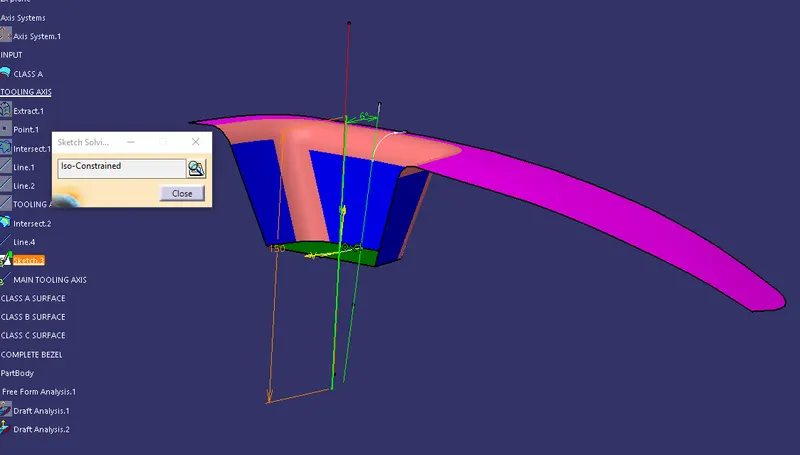
Using bisect command
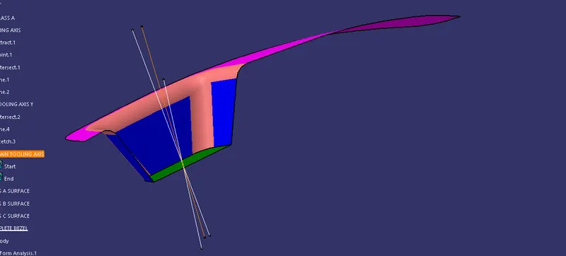
Objective 2: DRAFT ANALYSIS of Solid Switch bezel.
Procedure:
- After Tooling Axis Select the Feature Draft Analysis option from the Insert Option
 .
. - Select the element to analyze.
- Next click on Use the compass to define the new current draft direction option and make it align with the tooling axis by dragging it to the axis
 .
. - If the color appears blue just click the invert option on the right side of the draft direction axis button.
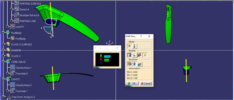
OBJECTIVE 3: Create Parting surface and line.
TREE:
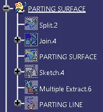
Procedure:
Of the class B Surface use the before offset command surface as extrapolated Class A surface.
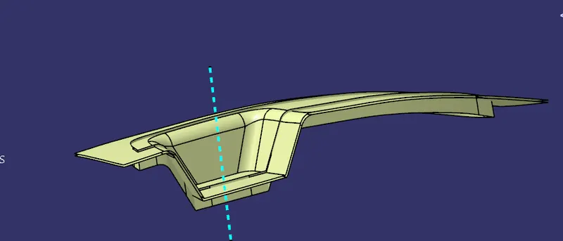
Trim the class A, B, and C to get the resulting surface.
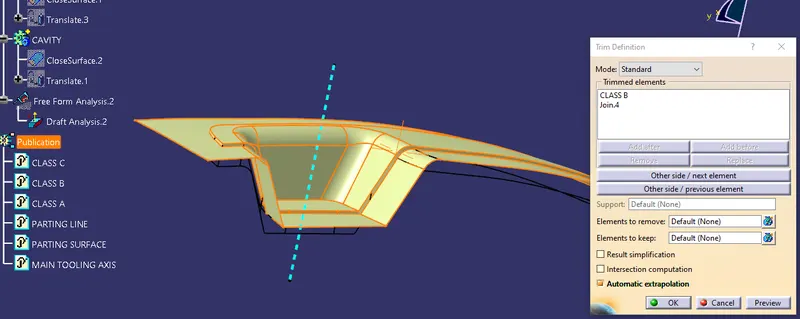
using Intersecting command intersect the class A and C surfaces to get the surface boundary for both the Classes.
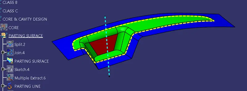
OBJECTIVE 4: Creating Core and Cavity components:
TREE:
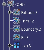
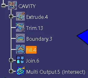
Procedure:
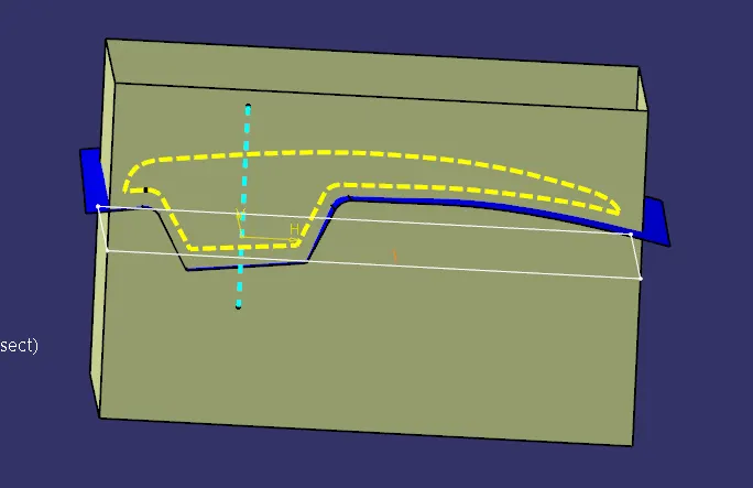
Create a Sketch of a rectangle just outside the parting line near inside the parting surface.
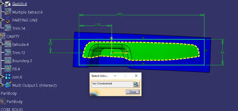
Extrude the sketch to the mirrored extent to clear some height over the surface intended in the direction of the tooling axis.
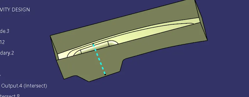
Trim with the parting surface.
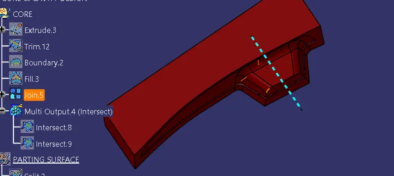
Create a boundary and fill the top area.
To create a closed surface go to the part workbench and use the Closed surface command to create a new body.
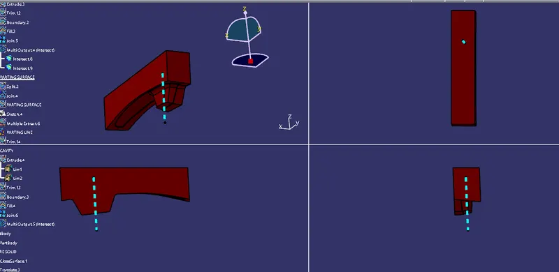
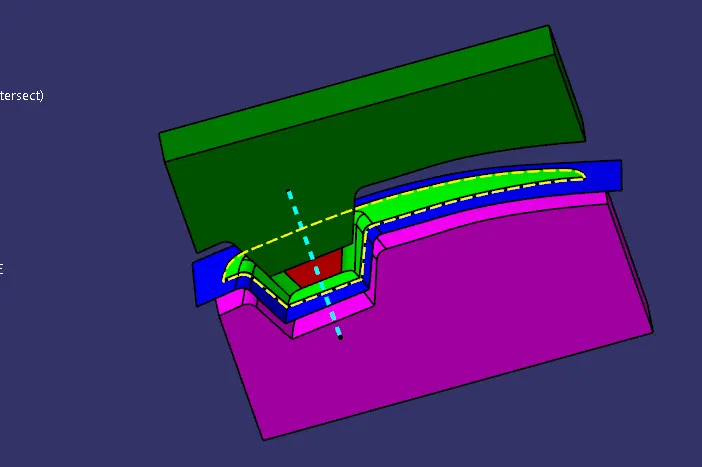
To understand more clearly here is an intersection of the YZ plane of the axis along the tooling axis created in both the core and parting surface.
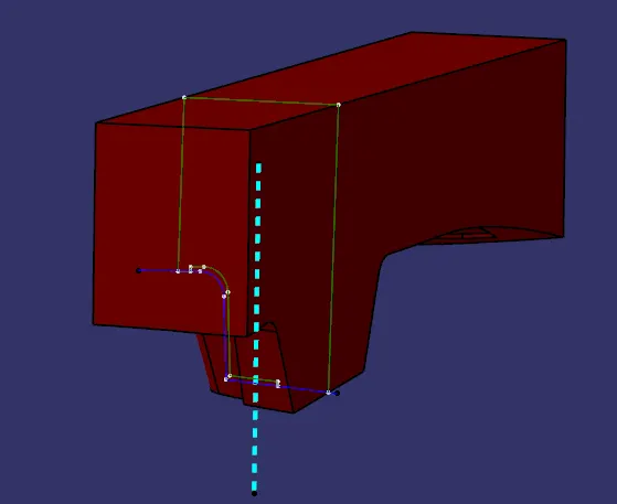
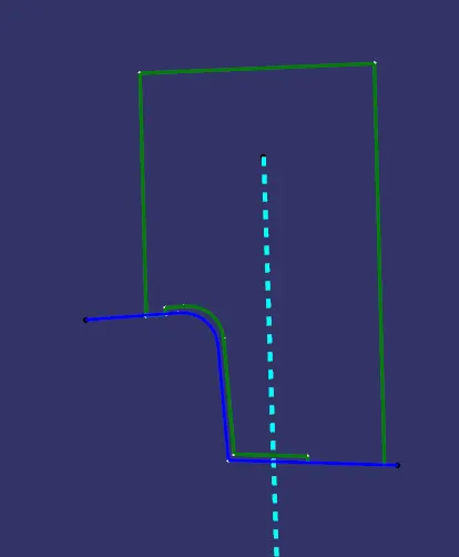
Similarly do for the Cavity of the part, instead of trim with parting surface use Class B surface.
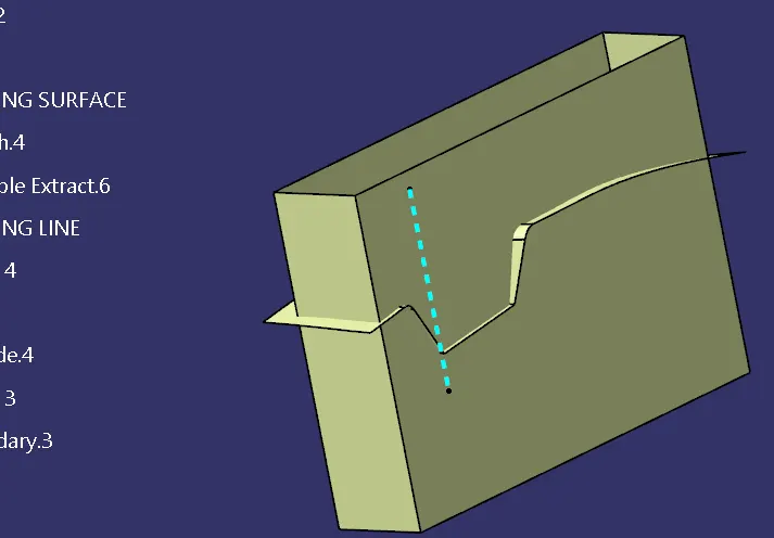
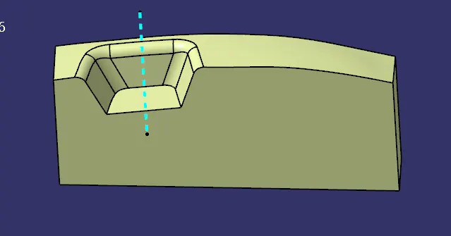
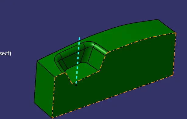
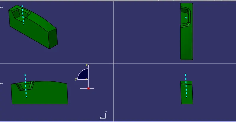
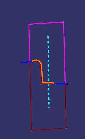
Intersection of both core and cavity with parting surface is as follows
Closed surface of both core and cavity with translation.
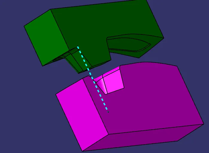
Component parting surface and parting line with core cavity.
CONCLUSION:
Created Core and cavity for Switch bezel with considering all the design parameters as discussed above.