Door Arm Rest Week 8 Challenge
AIM: Creation of Door Armrest and add thickness to it.
MAIN TREE:
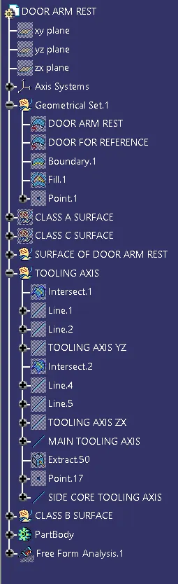
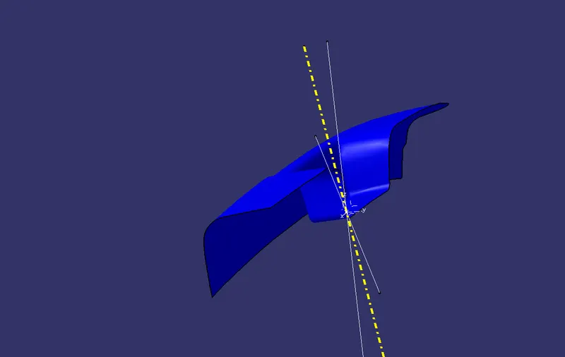
OBJECTIVE 1: Create a Tooling Axis for the Class A surface.
TREE:
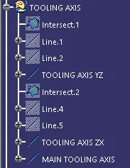
PROCEDURE:
- Create a point on the class A surface to move the main tool for component creation on the base surface.
- Mask an axis over the point created with the same directions as the main axis
 .
. - Using Intersect command from Generative Shape design select the YZ plane as the first element and the class A surface as the second element
 .
. - After creating the intersecting lines select the Line command and join the vertices which show the most possible draft angle manufacturable.
- Similarly, select the second axis and create intersecting lines but since only one side is available create a sketch of a line for the intersecting surfaces and make the draft line at an angle of 3 degrees.
- Bisect those two lines over the axis point we created
 .
.
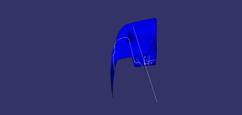
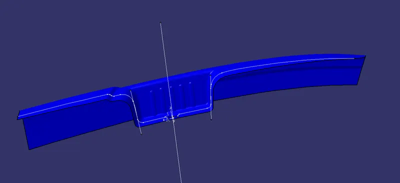
OBJECTIVE 2: DRAFT ANALYSIS of Class A surface:
PROCEDURE:
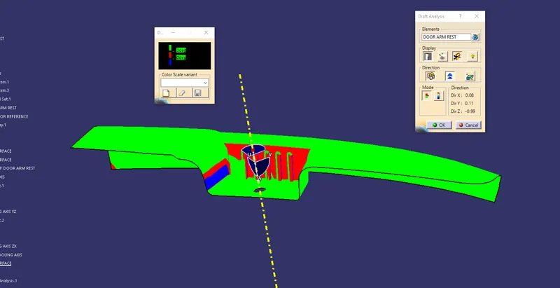
- After Tooling Axis Select the Feature Draft Analysis option from the Insert Option
 .
. - Select the element to analyze.
- Next click on Use the compass to define the new current draft direction option and make it align with the tooling axis by dragging it to the axis
 .
. - If the color appears blue just click the invert option on the right side of the draft direction axis button.
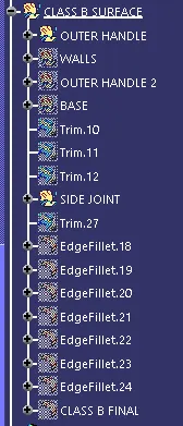
Objective 3: Create a CLASS B SURFACE :
TREE:
PROCEDURE:
OUTER HANDLE 1:
TREE:
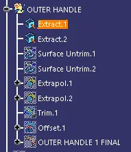
Using the Extract option select the first set of ribs from the Class A surface .
.
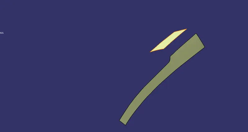
Then use the untrim surfaces command to restore the surfaces up to the limit .
.
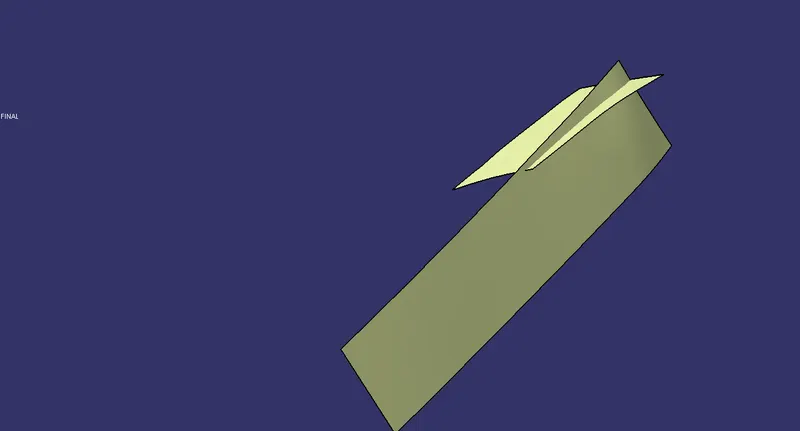
After that click the Extrapol command to extract the surface in the curvature direction .
.
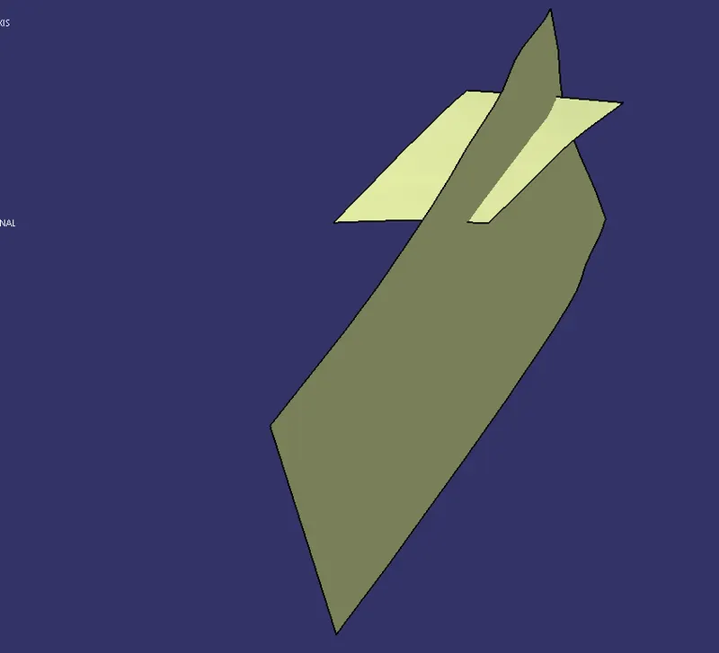
Finally use the trim command to cut the surfaces to get the desired output.
Set an offset to set a thickness of 2.5mm.
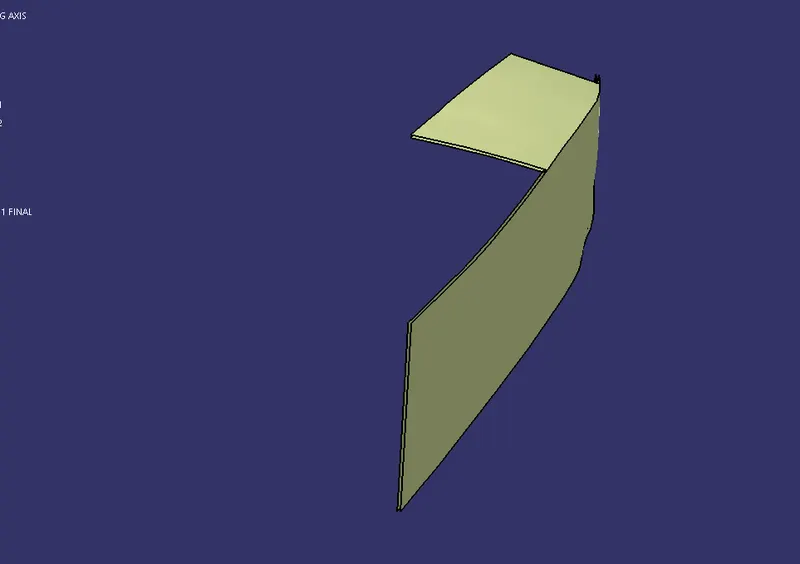
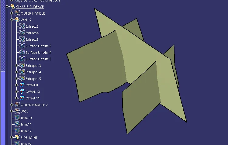
Similarly proceed to do the same for the rest of the parts final part is shown below each respective tree.
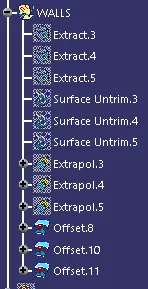
WALLS:
TREE:
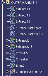
OUTER HANDLE 2:
TREE:
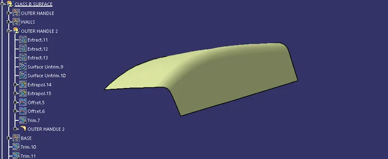
Here appropriate fillet was given at the end.
SIDE JOINT:
TREE:
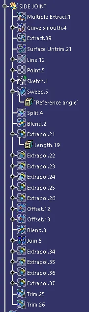
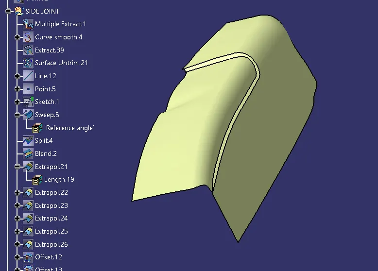
Here first the side was extrapolated length-wise and swept by creating a sketch line tangent to the two fillets at the side.
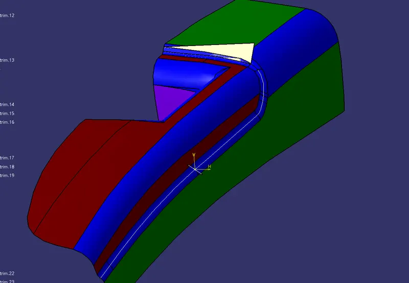
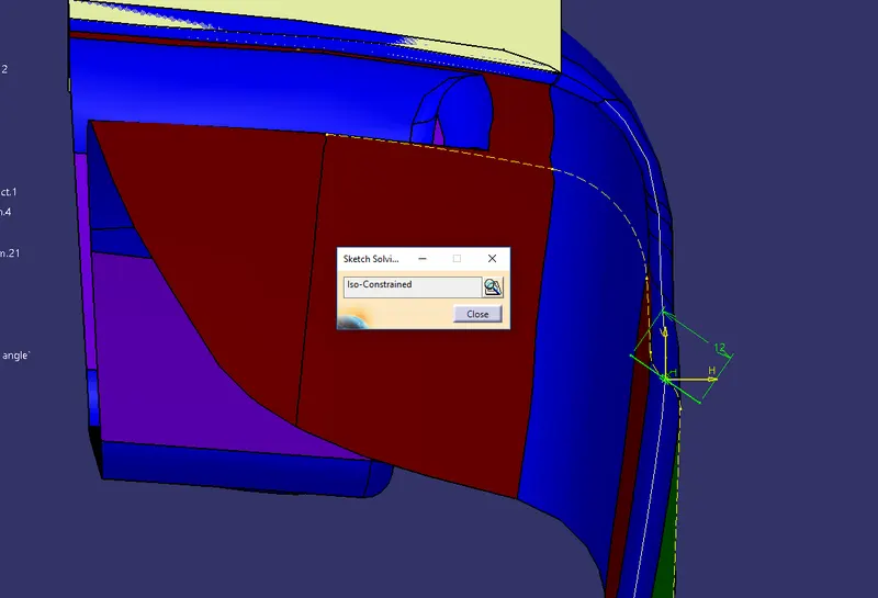
Next, it was swept along the given guide curve to intersect both the outer handles.
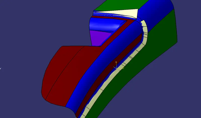
Using blend and extrapolate the two surfaces are joined.
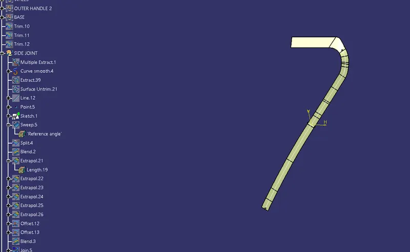
using trim the final surface is as follows.
BASE:
TREE:
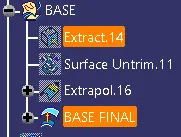
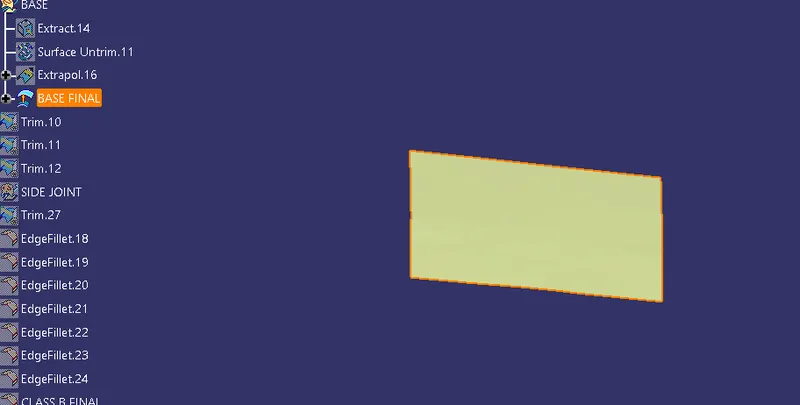
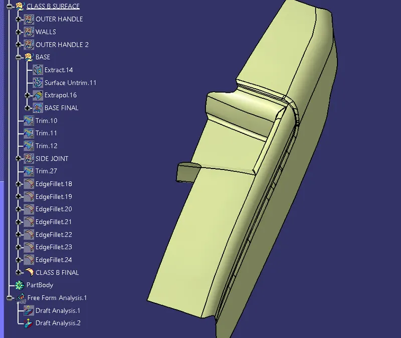
Finally, trim all surfaces.
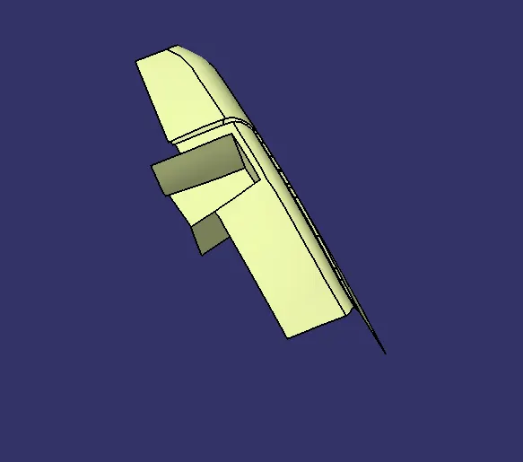
Give appropriate fillets.
Objective 4: Creating a CLASS C SURFACE
TREE:
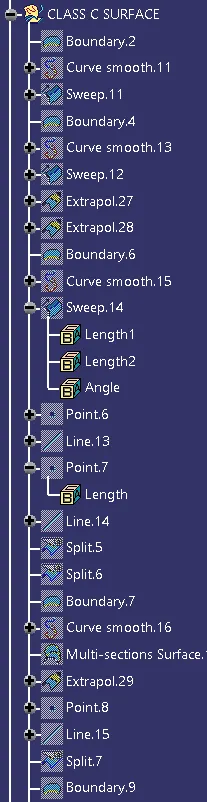
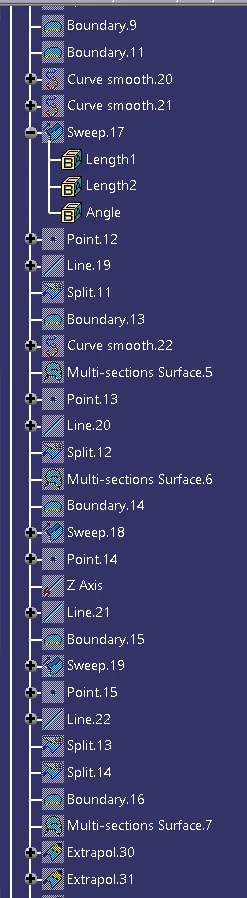
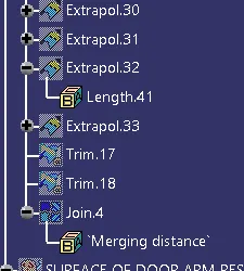
Here all the outer boundaries are extracted according to the requirements.
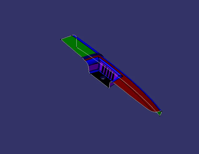
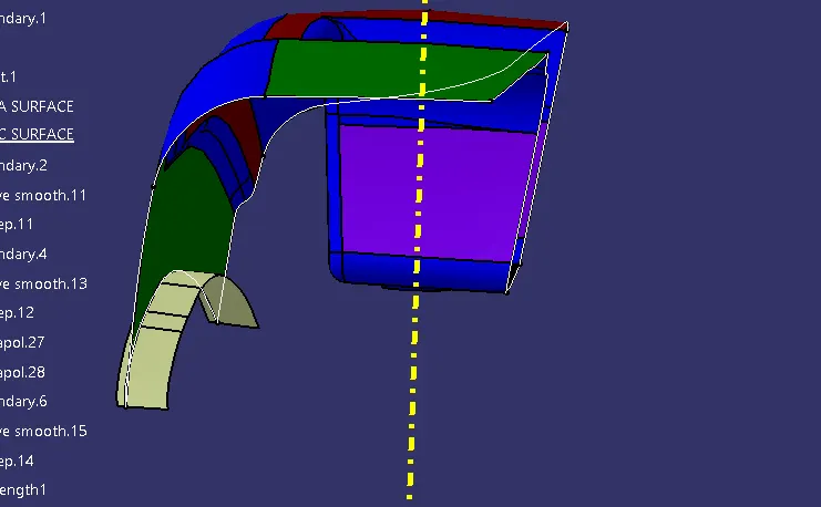
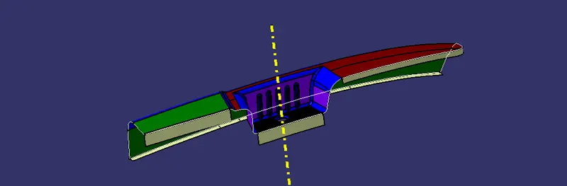
Since error occurs while forming the middle surface using a Multi-section surface the guide curves are used to extract the surface accordingly.
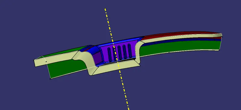
Similarly for the sides.
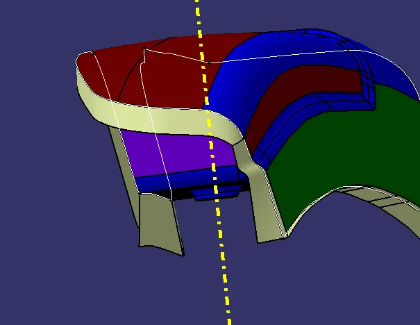
Finally, join the surfaces.
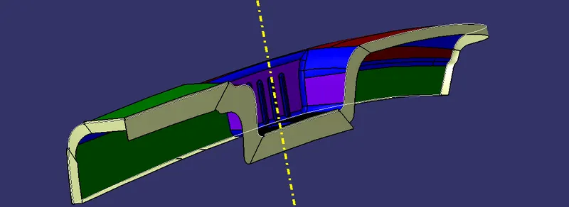
OBJECTIVE 5: DOOR ARM REST CREATION
TREE:
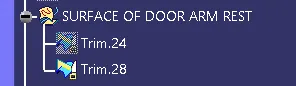
Trim all class A, B, and C surfaces:

Using the Closed Surface option create a solid part of the bracket.
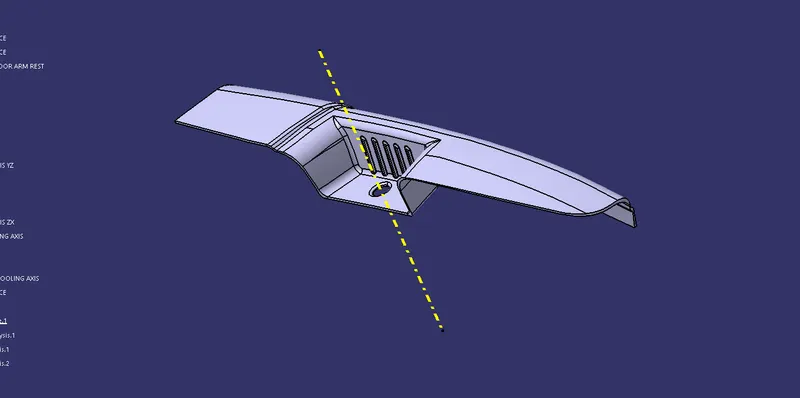
Objective 6: DRAFT ANALYSIS of the SOLID part
- Select the element to analyze.
- Next click on Use the compass to define the new current draft direction option and make it align with the tooling axis by dragging it to the axis.
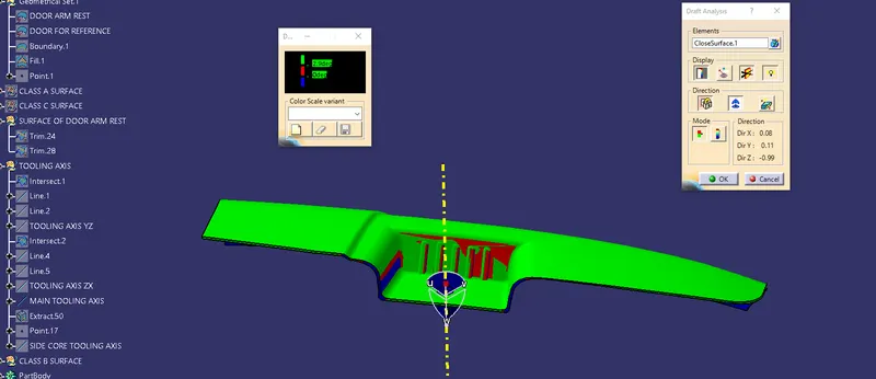
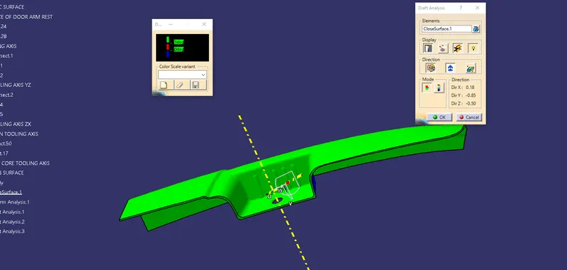
Drawing a side core axis for ribs structure and walls as they cannot be produced in the main tooling axis.

CONCLUSION:
Created a DOOR ARM REST Plastic component through the given Class-A surface and draft analyzed the surface with 3 degrees of draft angle with side core also.