Week 4-1D Element Creation Challenge
AIM: Mesh the Given component with the Size of 5 Units. Create 1D elements on the following component with given cross-section and DOF.
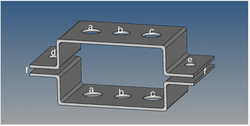
a. Rod element:- Translational DOF should be Constrained with RBE2 link
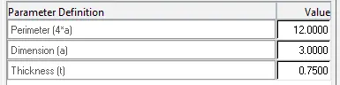
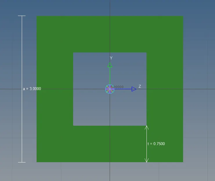
Cross-Section: BOX- Dimension a= 12 mm
dimension b=10 mm
Thickness t= 0.75 mm
b. Beam element:- All DOF should be constrained with RBE3 link
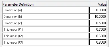
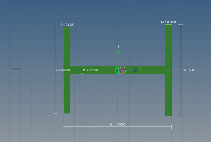
Cross-Section: I Section- Dimension a= 8 mm
Dimension b= 10 mm
Dimension c= 8.5 mm
Thickness t1= 0.75 mm
Thickness t2= .6 mm
Thickness t3= .6 mm
c. Bar element:- Constrain only x and y DOFs With RBE3 link
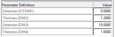
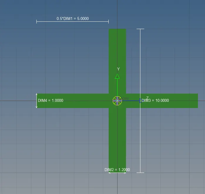
Cross-section: X Section- Dimension DIM1= 5 mm
Thickness DIM2= 1.2 mm
Dimension DIM3= 10 mm
Thickness DIM4= 1.2mm
d. & e. Apply the mass of magnitude 10 with the RBE2 link
f. Join the two components with Spring elements
INTRODUCTION:
Rod is a linear element type with a circular cross-section.
Bar can have any shape of the cross-section.
Beam is also a type of bar but it can have any loads such as axial, bending, and shear loads and also moments and torsional/torque loads.
Rigid Elements
A rigid element is used to rigidly connect two nodes of a model, or to transfer an external load on to the model.
Type of rigid elements used in the above model:
1. RBE 2:
RBE2 elements add infinite stiffness to the nodes being constrained.
2. RBE 3:
RBE3 elements provide a distributed connection, which does not influence the local (or global) stiffness of the model.
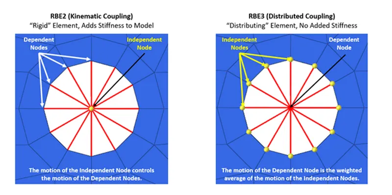
In the image on the left side where the independent node is moved by even a single mm then all the dependent nodes will move by 1 mm in the same direction as of independent node, which represents that the independent node is the governing node for other nodes and hence infinite stiffness is recieved. to the element.
Whereas the RBE3 element dsitributes the load from independent to dependent by averaging all the independent nodes movement and hence this type of connection does not contribute any stiffness to the model.
PROCEDURE:
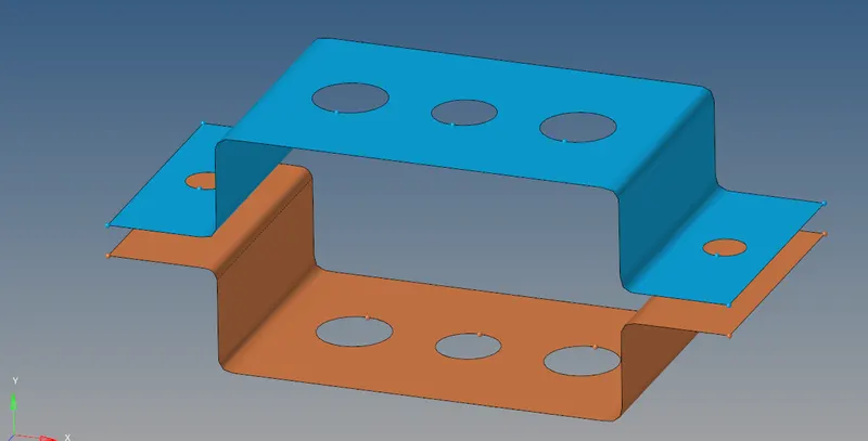
Extract mid surface from the two brackets and name them upper and lower body.
Apply washer splits with offset of 5 mm
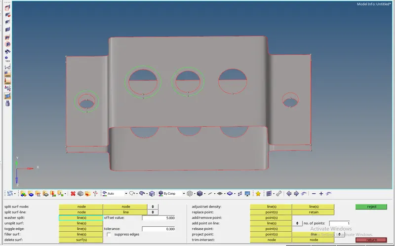
Apply 2D automesh with element size 5
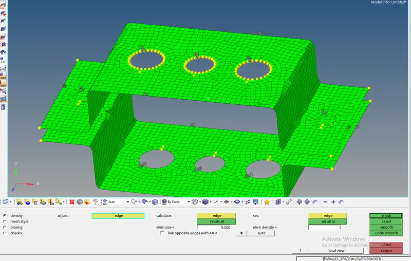
Fixed the holes accordingly to create a fine mesh to be then used for carrying out the rigid elements.
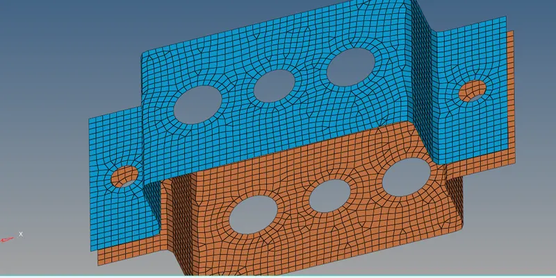
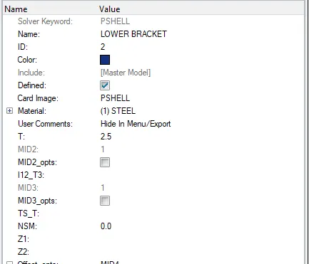
Create material and properties for the two brackets
MATERIAL: Upper Bracket Property: Lower Bracket Property
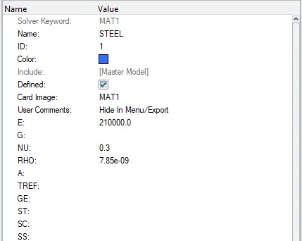
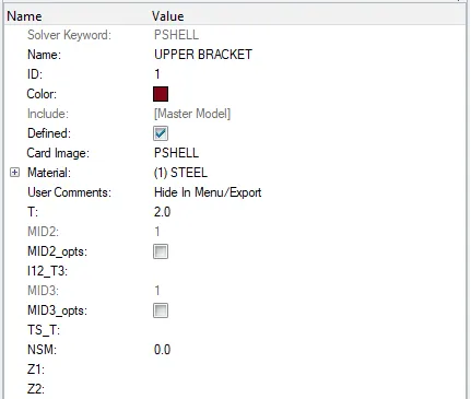
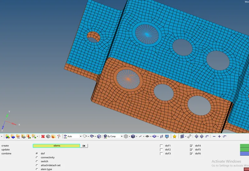
Apply RBE 2 elements to holes marked with "a" and translational DOF constrained.
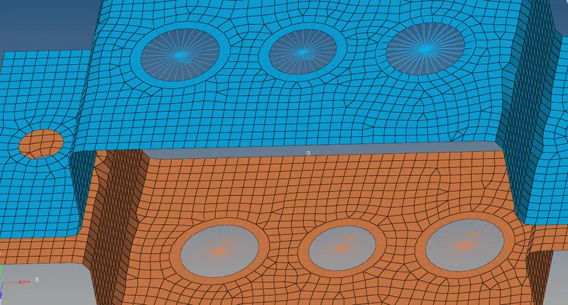
Apply RBE 3 elements to holes marked with "b" and "c" with all DOF and X,Y constrained respectively.
Create crossection for rod, beam and bar in Hyperbeam.
1) Beam:
Given dimension:
2) Rod:
Given Dimension:
3) Bar:
Given Dimension:
Create properties for beam, bar and rod by changing card image/ID and beam section as follows:
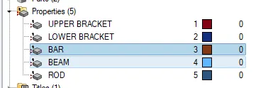
BAR BEAM ROD
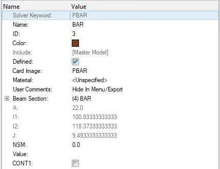
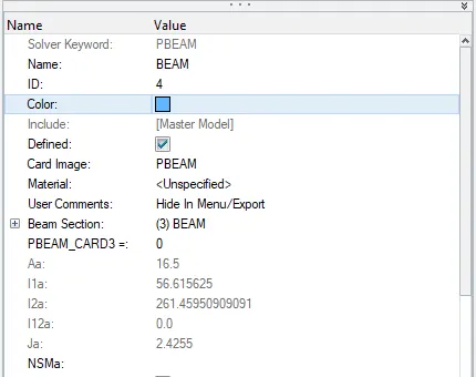
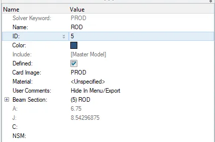
Using rod and bar from 1D menu bar create rod beam and bar with their respective properties.
BAR
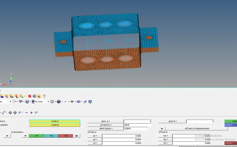
BEAM
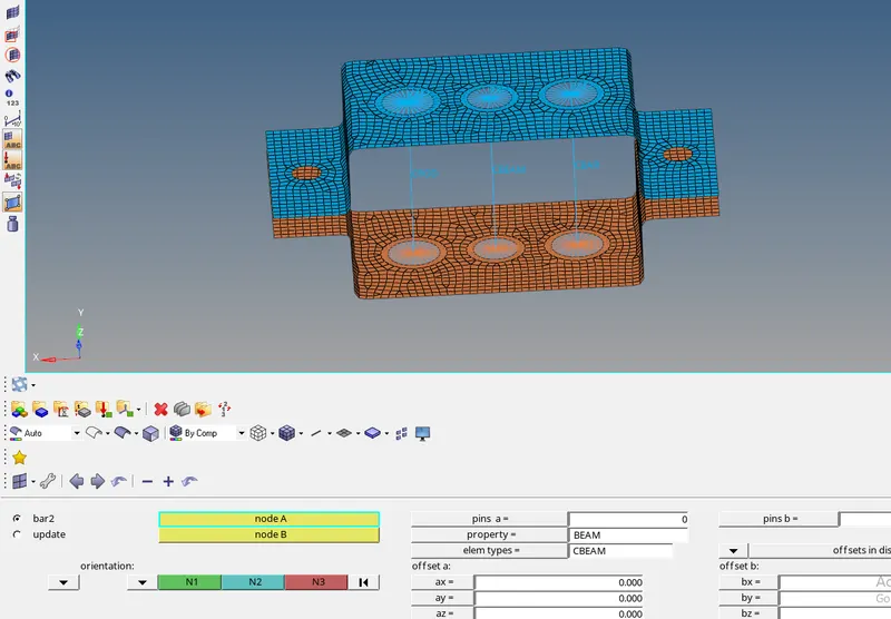
ROD
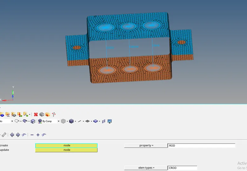
Create mass of 10 magnitude of "d" and "e" hole respectively but before that RBE 2 element should be present there to carry out the load.
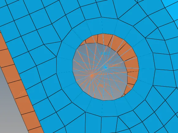
Apply the spring element with CELAS 1 element type with default properties and use the corner nodes to attach as shown in the detailed figure.
To get a detailed representation of 1D elemnet in 3D use 1D detailed elemnental representation mode.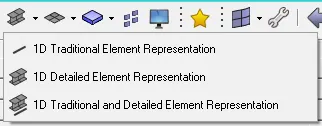
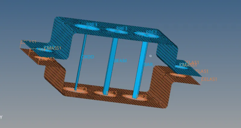
CONCLUSION:
In this challenege i studied the beam, rod and bar properties and how to apply axial load and translational load to different situations, learned the differenece between RBE 2 and RBE 3 elements, successfully created mid surface and 2D meshed the mid surface to create the RBE 2 and 3 elements respectively.