Project 1 : CFD Meshing for Tesla Cyber Truck
CFD MESHING OF TESLA CYBERTRUCK
Aim: To perform the CFD surface and volumetric meshing for the TESLA CYBERTRUCK model.
Introduction:
Procedure:
Geometrical Clean-up:
-Open the ANSA and import the Cybertruck model.
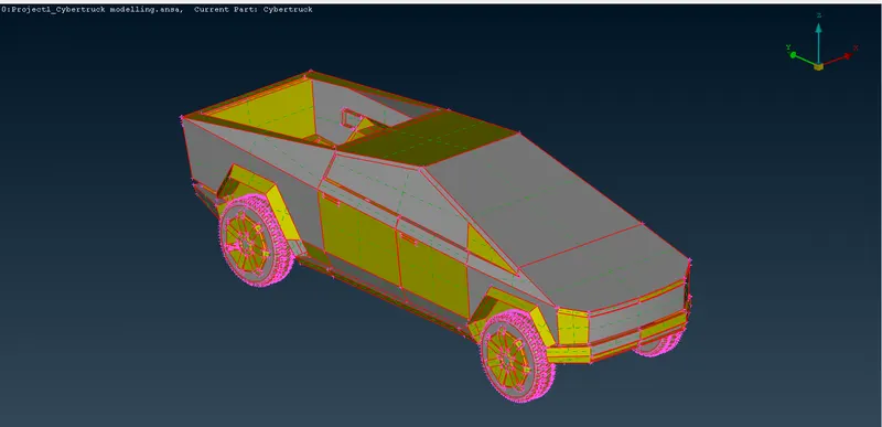
-There are all single cons on the model due to the tolerance gap between the faces. Use the Topo option in the Face module to join the surfaces.
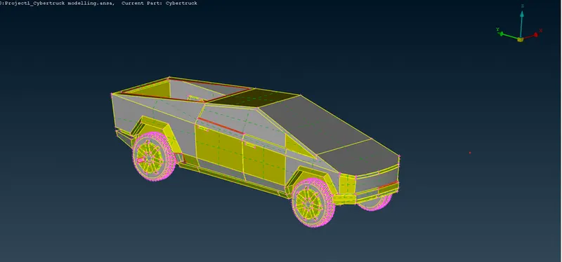
- As we can observe that the Cybertruck model is symmetrical, using the Plane Cut option in the Face module creates a cut over the model.
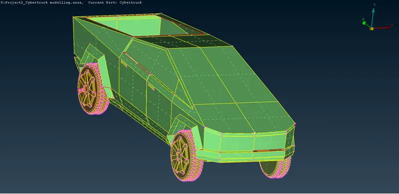
-Delete the right half of the model using the Delete option. It will be easy to operate on the left half of the model.
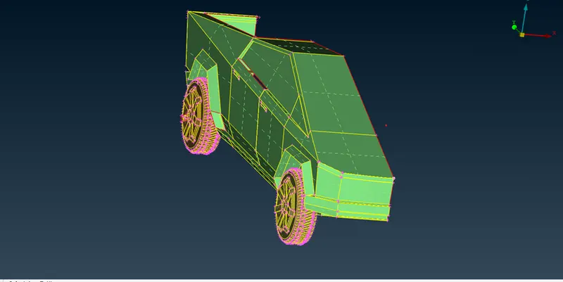
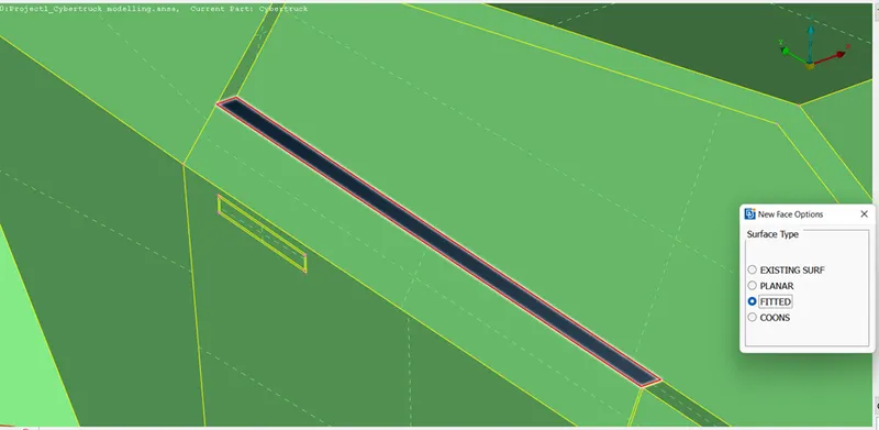
-There are a few missing surfaces in the model. Create new faces using the New option in the Face module.
 |
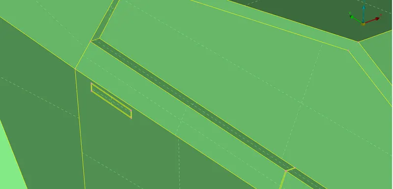 |
-Apply same process for all the missing faces.
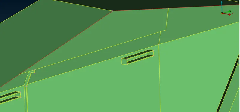
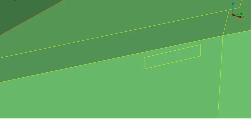
-Remove unnecessary faces present inside the model as they don’t have effect on results of external flow simulation.
 |
 |
-To check the geometrical errors in the model, use the Checks Manager tool.
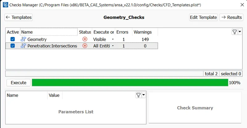
-As observed that there is a Penetration: Intersections error. This error occurs when two surfaces don’t intersect properly.
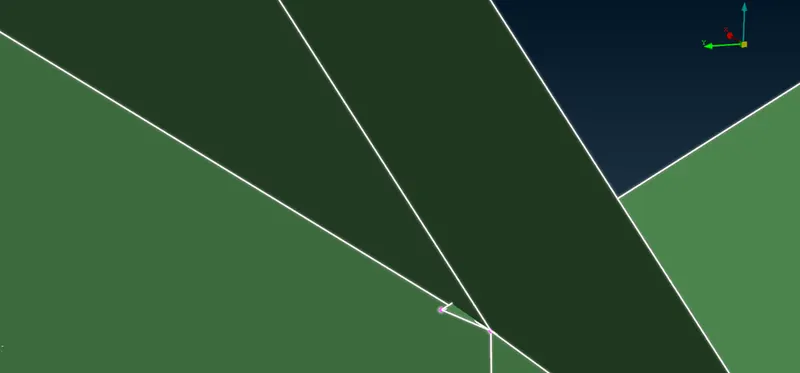
-To rectify this error, use the Intersection tool in the Face module. Select the faces that are need to intersect. Delete the extra faces.
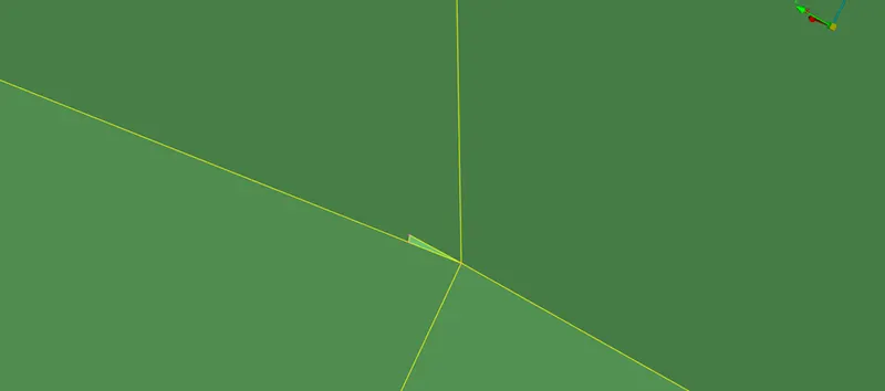
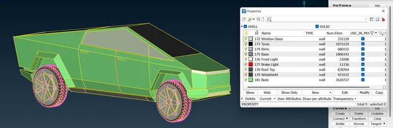
-After rectifying the error, assign the PIDs for the faces. To create new PID, open Properties (CTRL+P) then right click and click on New. Assign the name for the PID. To assign face to PID right click on the PID and click on the Apply and select the face.
Surface Meshing:
-Use the Measure tool to measure the distance between the different Cons. It helps to decide the target length for the surface meshing.
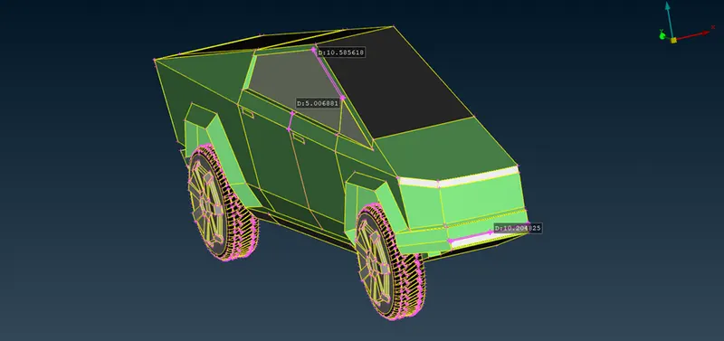
-From the above observation, let us take 3mm as target length with tri elements.
-Click on the Spacing option in the Perimeters module in the Classic Mesh deck. Opt for Auto-CFD option. Click on the Perimeters option and select the model. Middle click to complete the selection.
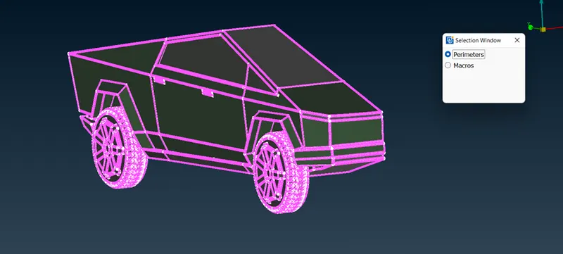
-Specify the Maximum target length as 3.5mm and Minimum target length as 2.5mm. Same for the Macros.
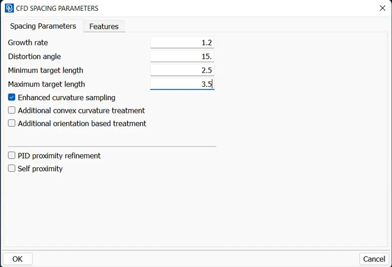
-Set Mesh Parameters as shown in the below image. Click on Apply then on Ok.
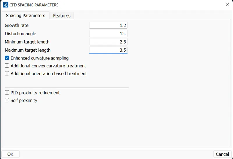
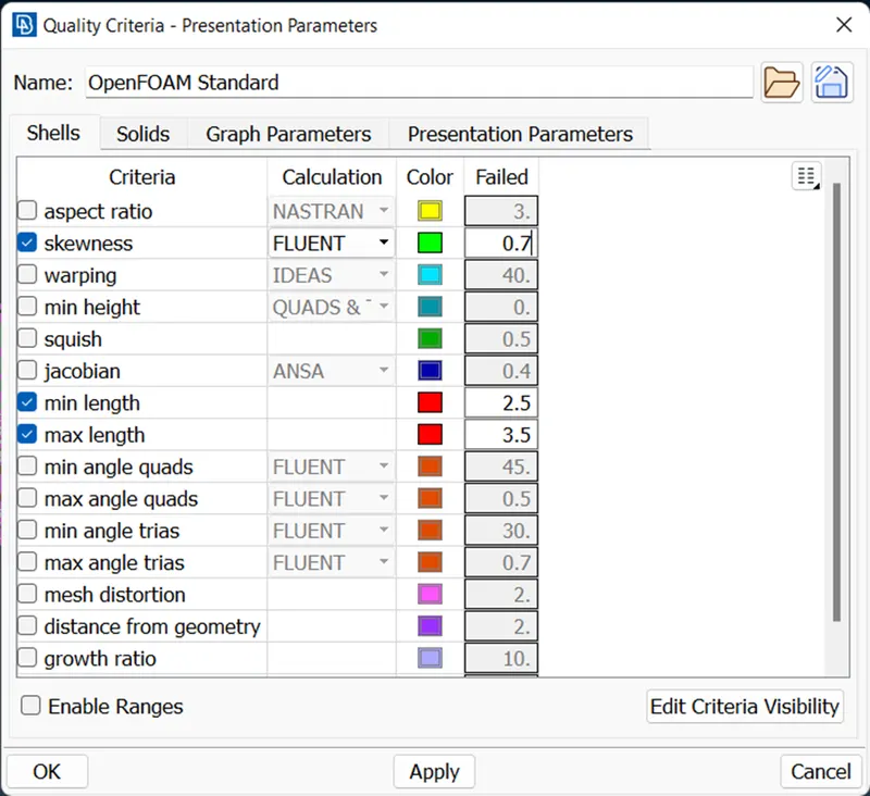
-Set the Quality Criteria as shown in the image below. Click on Apply then on Ok.
-For CFD meshing of the surface of the model, click on the CFD option in the Mesh Generation module. Select all the faces that are to have meshed.
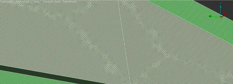
-Make sure to have almost zero off elements (falls under quality criteria). Use the Reconstruction tool in the Shell Mesh module.
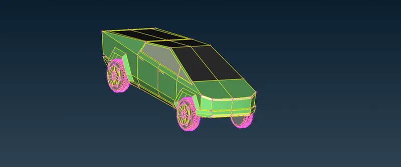
-Complete the model by creating another half of the model using the Transform tool. Click on the Copy option of the Transform tool and select the entities. Opt for symmetry with a 3-point Mirror Plane. Select the points and click on the finish to complete the process.
Wind Tunnel:
-The geometry of the wind tunnel is as follows
|
Car Length |
x |
5906 |
|
Inlet from Car |
4x |
23624 |
|
Outlet from Car |
6x |
35436 |
|
Top wall from Car |
3x |
17718 |
|
Each Sidewall from the Car |
x |
5906 |
|
Bottom wall from Car (Clearance) |
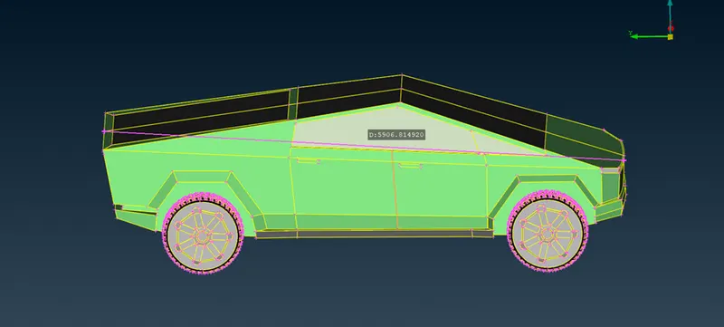
-Length of the model is measured using the Measure tool. Based on the length of the model perimeters of the wind tunnel are calculated.
-Using the Relative option in the Points module, create the points in the space. Join those points using the Create option in the Curve module.
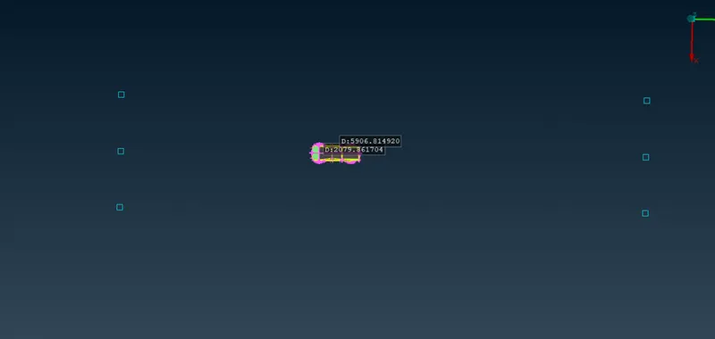
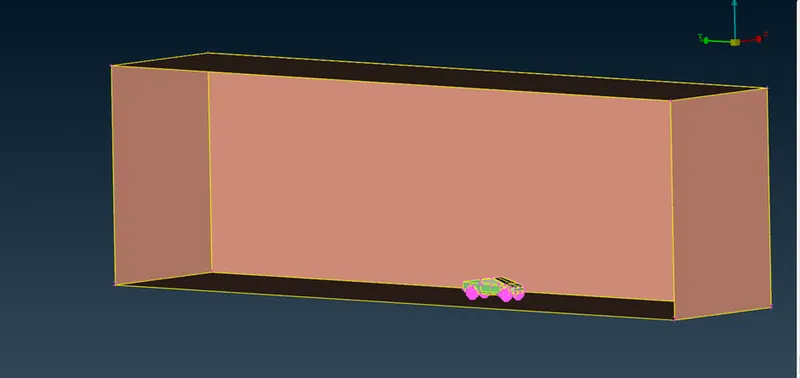
-Create a new surface as a Bottom wall using those curves. Offset the surface for the top wall using the Offset option in the Face module. Similarly, create the remaining side walls using the Face option.
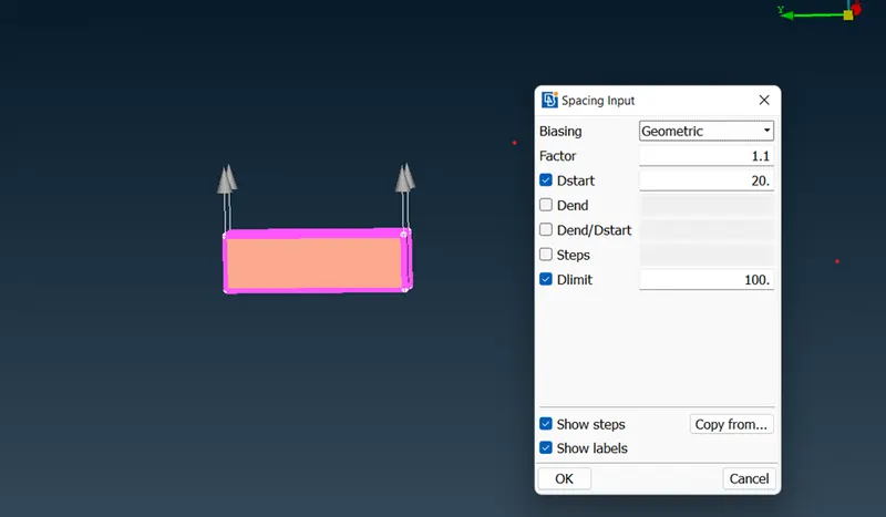
-For the surface meshing of the wind tunnel, opt for the Spacing option in the Perimeter module and specify the growth as 1.1, dstart as 20mm and dlimit as 100. Select the cons as shown below. The direction of the vector should be pointing upwards.
-Specify the mesh parameter with 100mm as the target length and, 20mm and 100 mm as maximum and minimum length.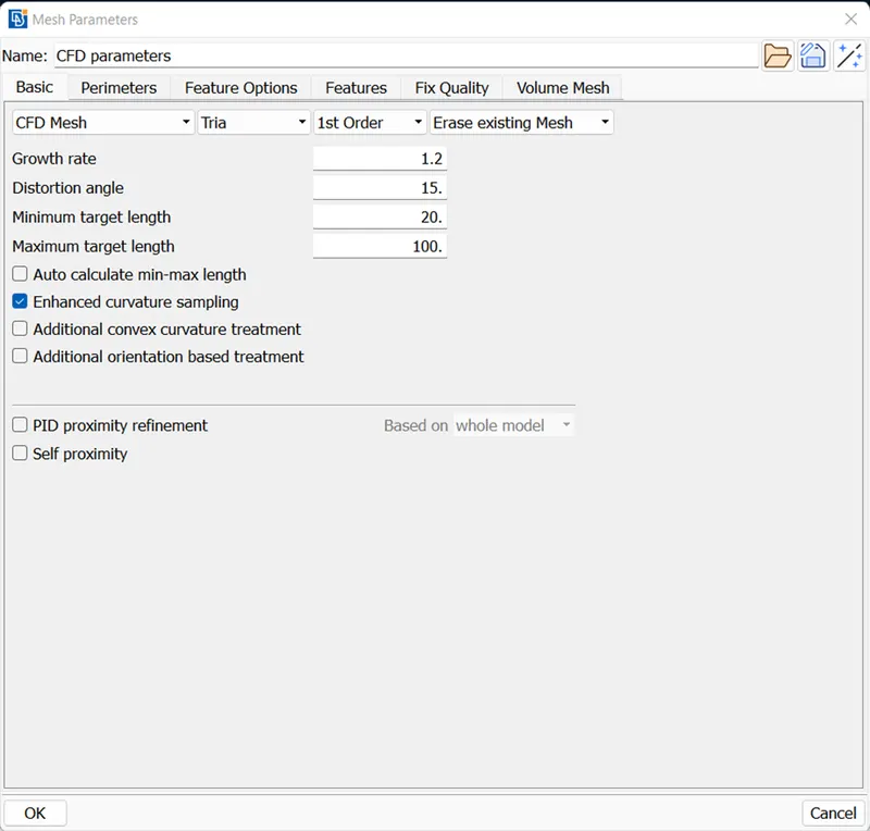
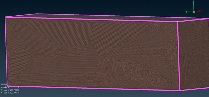
-Click on the CFD option in the Mesh Generation module, and opt for Visible to mesh the wind tunnel surface.
Volumetric Meshing:
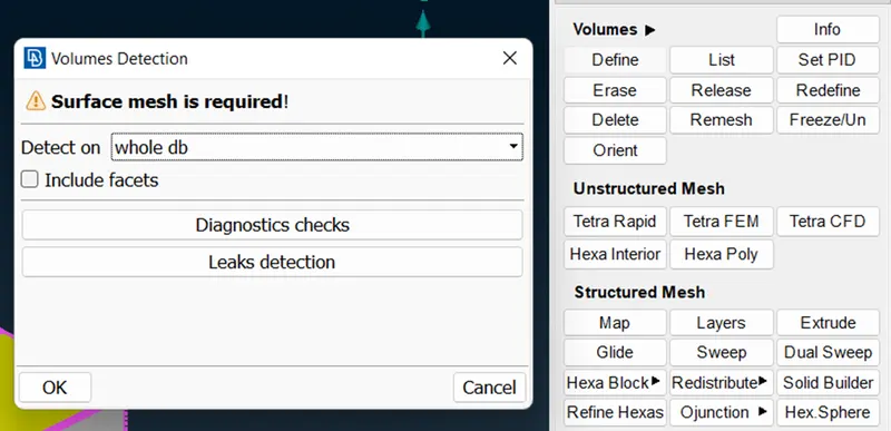
-Click on the Define option in the Volumes module of the Volumetric Mesh deck. A list of 6 auto-identified volumes will be present.
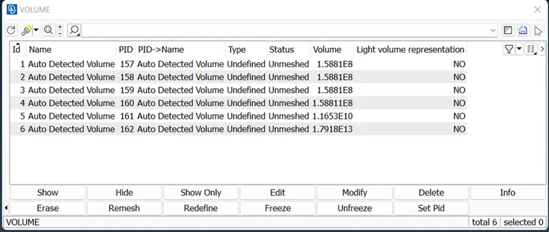
-Delete all the unnecessary volumes. Leave the volume that is to be meshed.
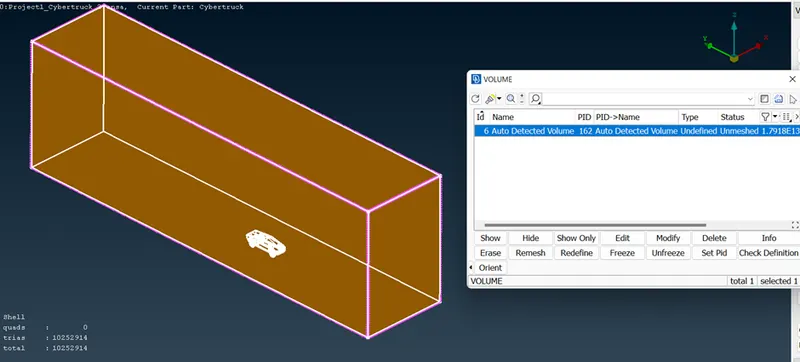
-Click on the Tetra CFD option in the Unstructured Mesh module and choose the volume to mesh
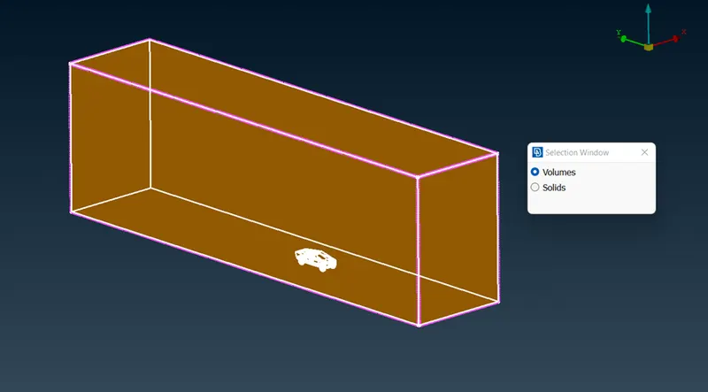
-We do not perform volumetric mesh as it will take a huge amount of computational time and effort which can not be done using a regular personal computer or laptop.
Conclusion:
In this project, we imported the Tesla Cyber Truck model and did a topologically clean-up, and corrected all the surfaces. Created a wind tunnel for external aerodynamic simulation analysis. The surface mesh is generated for the Cyber Truck model and the wind tunnel. Reconstructed the off elements with respect to the mesh quality.
Model:
https://drive.google.com/file/d/1w8d230d9yJDsuziVQU87HeHeu8hYRP-N/view?usp=sharing