Week 8 - Simulating Cyclone separator with Discrete Phase Modelling
SIMULATING CYCLONE SEPARATOR WITH DISCRETE PHASE MODELLING
AIM:- To perform analysis on cyclone separator and calculate the separation efficiency and pressure drop.
INTRODUCTION:-
A cyclone separator is a mechanical device used to separate heavy dust particles from gas or air. It has a simple geometrical design and can work efficiently to remove large particles from the air. With the continuous feed of gas containing particulate matter through the inlet of the cyclone separator, the vortex inside the cyclone separator moves the gas in a spiral motion. The heavier particle in the gas collides with the walls and falls into the collection chamber. The lighter particle, influenced by the vortex, moves upwards and escapes from the outlet at the top.
A cyclone separator is used as a pollution control device in the pre-cleaning process of flue gases. It is important to design a more efficient cyclone separator which gives better performance. The efficiency of the cyclone separator is measured through its particle collection efficiency and pressure drop.
In this project, the simulation of the cyclone separator is carried out using NSYS Fluent to predict the efficiency of the separator and compare it with the efficiency calculation of empirical models.
EMPIRICAL MODEL FOR CALCULATION OF SEPARATOR EFFICIENCY:
Following are the few empirical models that are used for the prediction and calculation of cyclone efficiency
- IOZIA AND LEITH MODEL
Iozia and Leith’s force balance-based model assumes that particle is carried by the vortex due to the influence of centrifugal force and flow resistance. The collection efficiency ηi
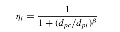
β is an expression for slope parameter derived based on the statistical analysis of experimental data of a cyclone with D = 0.25 m given as

And dpc is given as
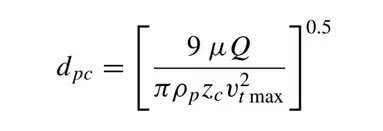
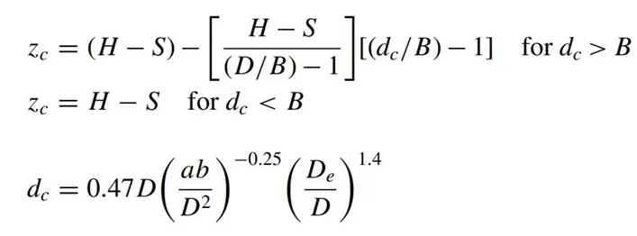
where core length, zc, and core diameter, dc, are given as
- LI AND WANG MODEL
The Li and Wang model include particle bounce or re-entrainment and turbulent diffusion at the cyclone wall. A two-dimensional analytical expression of particle distribution in the cyclone is obtained. Li and Wang’s model was developed based on the following assumptions:
- The radial particle velocity and the radial concentration profile are not constant for uncollected particles within the cyclone.
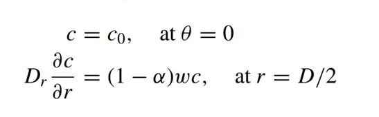
- Boundary conditions with the consideration of turbulent diffusion coefficient and particle bounce re-entrainment on the cyclone wall are:
- The tangential velocity is related to the radius of the cyclone by:
u Rn = constant
The concentration distribution in a cyclone is given as:
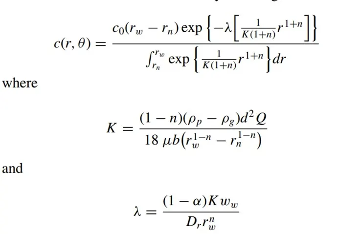
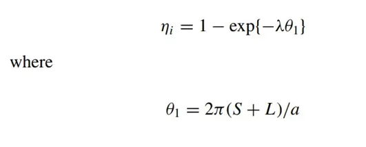
The resultant expression of the collection efficiency for particles of any size is given as
- KOCH AND LICHT MODEL
Koch and Licht’s collection theory recognized the inherently turbulent nature of cyclones and the distribution of gas residence times within the cyclone. Koch and Licht described particle motion in the entry and collection regions with the additional following assumptions:
- The tangential velocity of a particle is equal to the tangential velocity of the gas flow, i.e., there is no slip in the tangential direction between the particle and the gas.
- The tangential velocity is related to the radius of the cyclone by: u Rn = constant.
A force balance and an equation on the particles collection yield the grade efficiency ηi
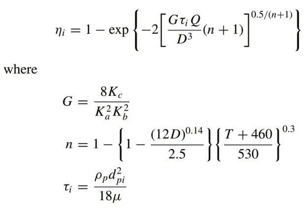
G is a factor related to the configuration of the cyclone, n is related to the vortex and τ is the relaxation term.
- LAPPLE MODEL
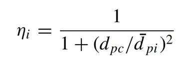
Lapple’s model was developed based on force balance without considering the flow resistance. Lapple assumed that a particle entering the cyclone is evenly distributed across the inlet opening. The particle that travels from the inlet half-width to the wall in the cyclone is collected with 50% efficiency. The semi-empirical relationship developed by Lapple to calculate a 50% cut diameter dpc is
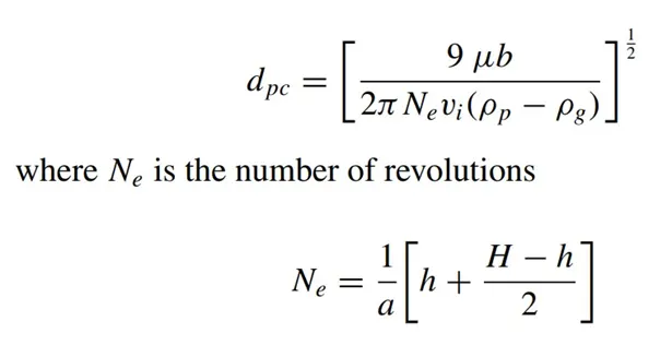
The efficiency of collection of any size of the particle is given by
SIMULATION MODELLING APPROACH:
- The objective of this simulation is to find the influence of inlet velocity and particle diameter on the separation efficiency and pressure drop of the cyclone separator.
- The fluid involved in this simulation is particulate matter suspended in the air, Discrete Phase Model is applied for this simulation. This model is capable of tracking individual particles.
- We assume the particle material to be anthracite injected into the cyclone separator.
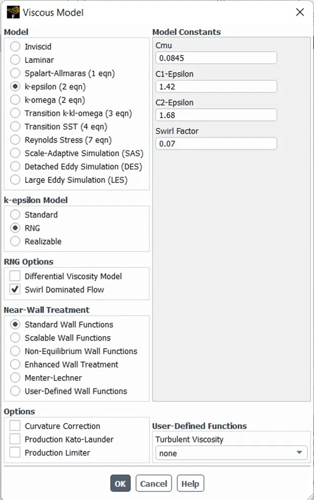
- To capture the vortex phenomenon inside the cyclone, k-epsilon with RNG viscous model with the swirl-dominated flow is enabled.
PROCEDURE:
Workbench Project:
-Open ANSYS Workbench and drag and drop Fluent.
-Click on File and save the project as “Cyclone_Separator”.
Geometry:
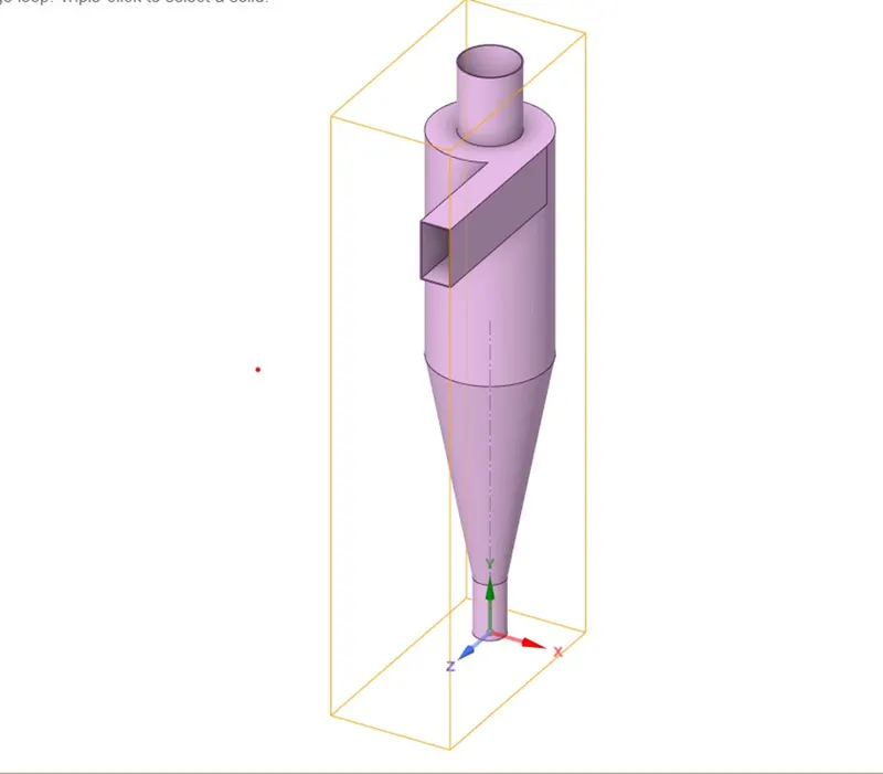
-Open ANSYS Space Claim and import the downloaded geometry.
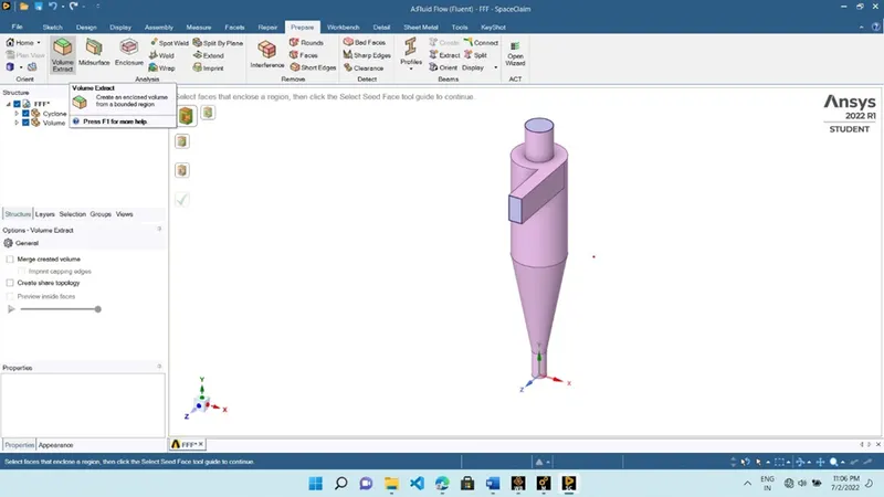
-Extract the fluid volume using the volume extract tool.
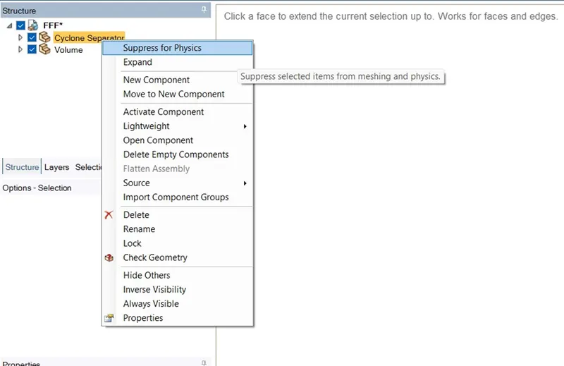
-Suppress the physics for the cyclone separator body.
-Click on File and save the project.
Meshing:
-Open ANSYS Meshing. Select the faces and specify the name for the inlet and outlets
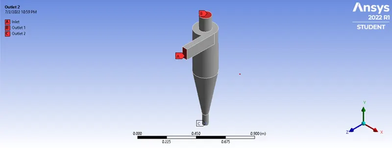
-Opt for Body Fitted Cartesian Meshing Method with 10mm s element size.
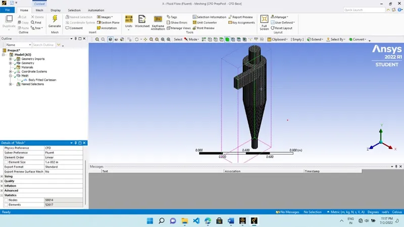
-Click on File and save the project
Fluent Setup:
-Open ANSYS Fluent and set up the simulation as mentioned below.
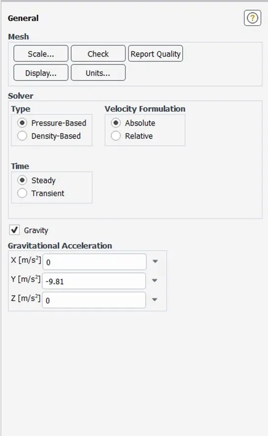
-Check the solver time as Steady
-Check the gravity and specify -9.81 m/s in the Y-direction.
-Select the k-epsilon viscous model with RNG for swirl-dominated flow.
-Turn on the Discrete Phase Model and check the Interaction with Continuous Phase for coupled flow.
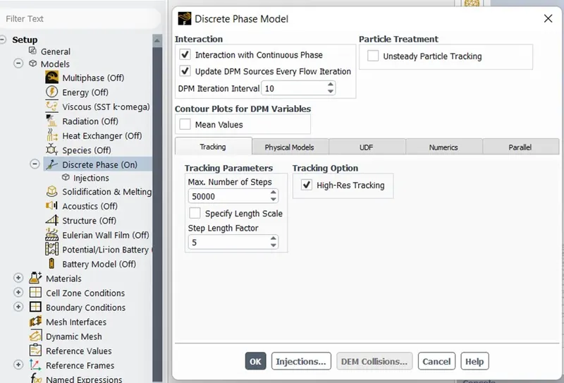
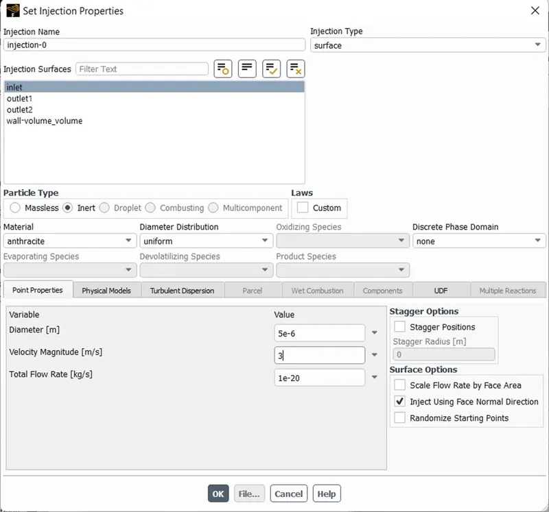
-Set the Injection properties with the following setup
-Injection Type: Surface
-Injection Surface: Inlet
-Particle Type: Inert
-Material: Anthracite
-Check the Inject Using Face Normal Direction to set particle flow normal to the face of the inlet.
-Particle Diameter and Velocity Magnitude are specified according to the simulation case.
-Setup the following boundary conditions
- Inlet Discrete Phase BC Type: Reflect
- Wall Discrete Phase BC Type: Reflect
- Outlet 1 Discrete Phase BC Type: Escape
- Outlet 2 Discrete Phase BC Type: Trap
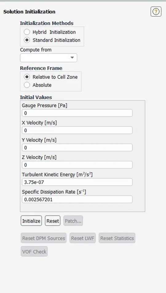
-Initialize the solution with Standard Initialization compute from the inlet.
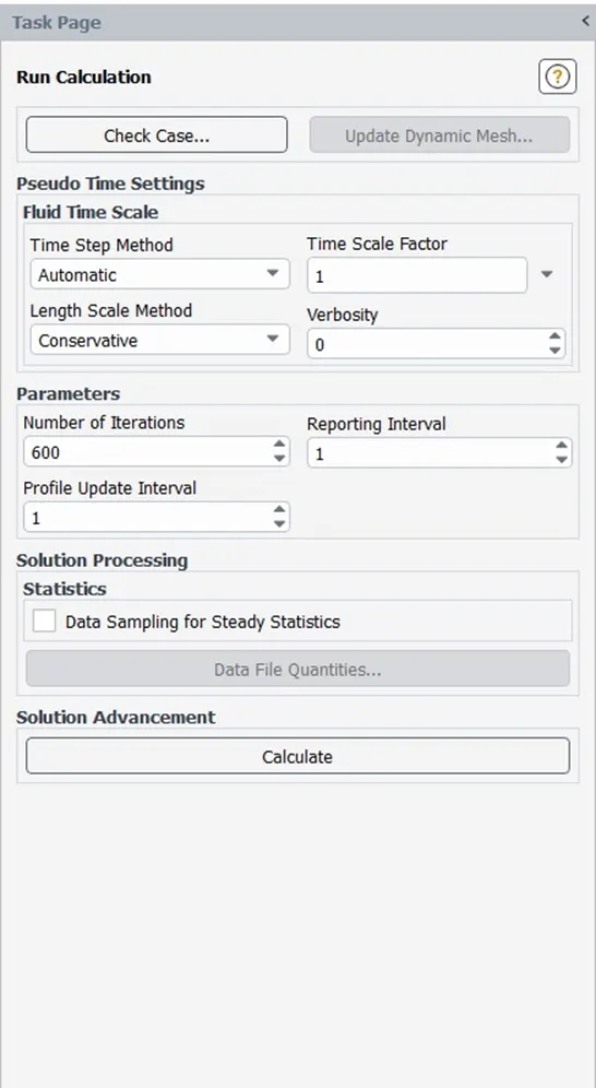
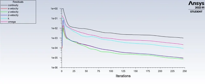
-Run the calculation until a solution is converged.
RESULTS:
Case 1: Effect on separation efficiency and pressure due to particle diameter
Case a: 1`mu`m with velocity 3m/s
Residual plot
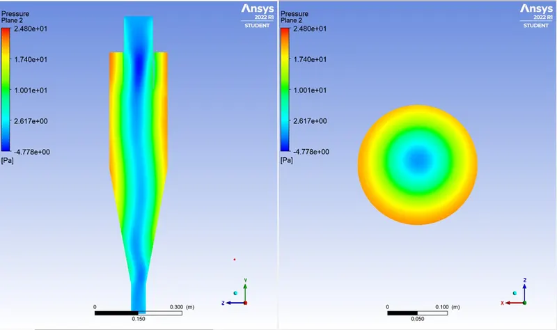
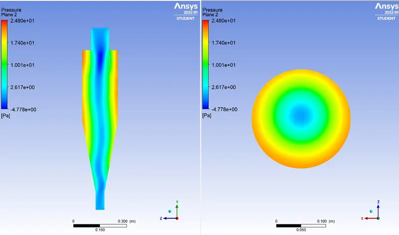
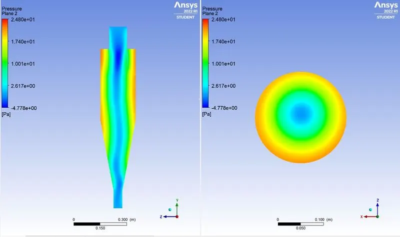
Static Pressure Contour
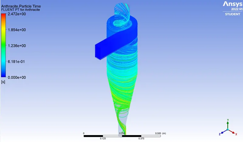
Separator Efficiency

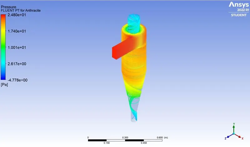
Particle Time Contour
Case b: 2.5`mu`m with velocity 3m/s
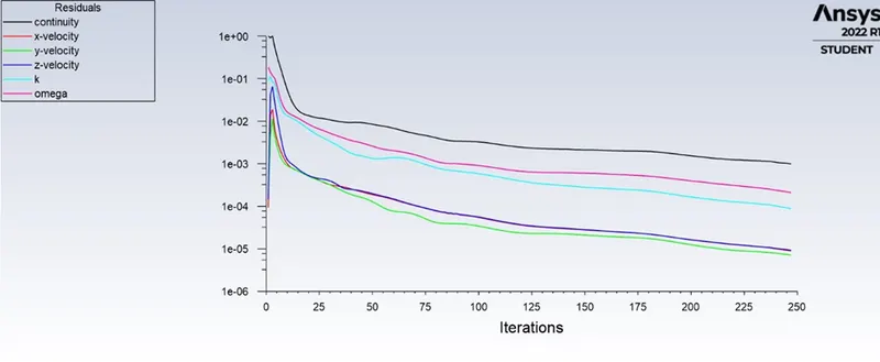
Residual plot
Static Pressure Contour
Separator Efficiency

Particle Time Contour
Case c: 5`mu`m with velocity 3m/s
Residual plot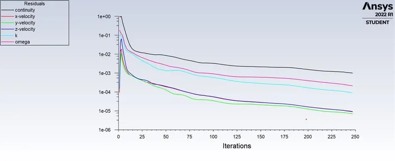
Static Pressure Contour
Separator Efficiency

Particle Time Contour
Case 2: Effect on separation efficiency and pressure drop due to inlet velocity
Case 1: 5`mu`m with velocity 1m/s
Residual plot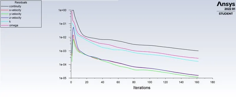
Static Pressure Contour
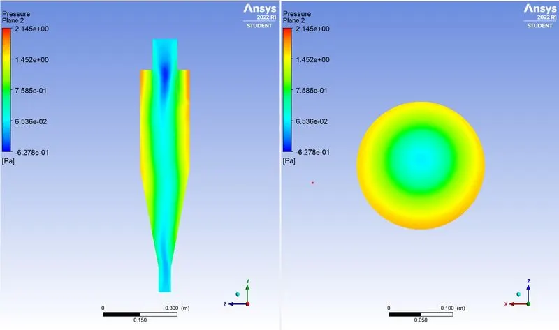
Separator Efficiency

Particle Time Contour
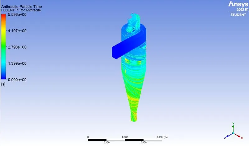
Case 2: 5`mu`m with velocity 2.5m/s
Residual plot
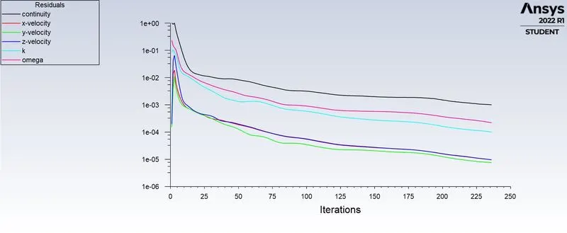
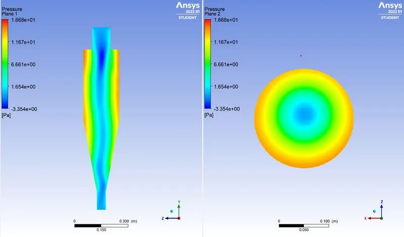
Static Pressure Contour
Separator Efficiency

Particle Time Contour
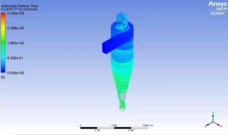
Case 3: 5`mu`m with velocity 5m/s
Residual plot
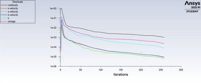
Static Pressure Contour
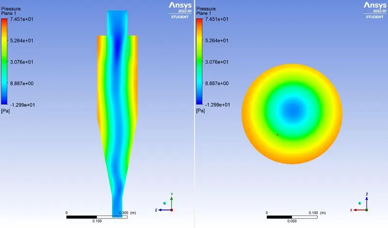
Separator Efficiency

Particle Time Contour
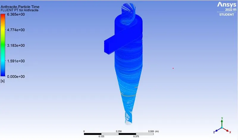
Case 1: Effect on separation efficiency and pressure drop due to particle diameter
Separator Efficiency
|
Inlet Gas Velocity |
Particle Diameter |
No. of Particle Tracked |
No. of Particle Trapped |
Collection Efficiency |
|
3 m/s |
1 `mu`m |
378 |
310 |
82.01% |
|
2.5 `mu`m |
311 |
82.27% |
||
|
5 `mu`m |
280 |
72.75% |
Separator Efficiency = (No. of Particle Trapped / No. of Particle Tracked)*100
Pressure Drop
|
Inlet Gas Velocity |
Particle Diameter |
Inlet Pressure |
Outlet Pressure |
Pressure Drop |
|
3 m/s |
1 `mu`m |
23.1626 Pa |
0 Pa |
23.1626 Pa |
|
2.5 `mu`m |
22.9161 Pa |
0 Pa |
22.9161 Pa |
|
|
5 `mu`m |
22.7816 Pa |
-0.0022Pa |
22.7838 Pa |
Case 2: Effect on separation efficiency and pressure drop due to inlet velocity
Separator Efficiency
|
Inlet Gas Velocity |
Particle Diameter |
No. of Particle Tracked |
No. of Particle Trapped |
Separator Efficiency |
|
1 m/s |
5 `mu`m |
378 |
307 |
81.21% |
|
3 m/s |
294 |
77.77% |
||
|
5 m/s |
284 |
75.13% |
Pressure Drop
|
Inlet Gas Velocity |
Particle Diameter |
Inlet Pressure |
Outlet Pressure |
Pressure Drop |
|
1 m/s |
5 `mu`m |
1.917 Pa |
-0.00059 Pa |
1.917 Pa |
|
3 m/s |
16.45 Pa |
-0.00977 Pa |
16.356 Pa |
|
|
5 m/s |
72 Pa |
-0.027 Pa |
72.027 Pa |
CONCLUSION
In this simulation, we can observe the change in separator efficiency due to the change in velocity of the particle and gas, and size of the particle.
Cyclone efficiency is influenced by various parameters such as inlet velocity, particle size and density, length of the cyclone separator, the diameter of inlet and outlets, etc.