Week 11 - Simulation of Flow through a pipe in OpenFoam
Objective: To automate and generate blockMeshDict file by creating a MATLAB script.
To simulate Incompressible Laminar flow through pipe Using OpenFOAM.
To validate the simulation results with theoretical results.
Theory
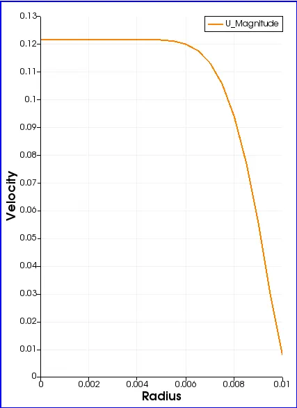
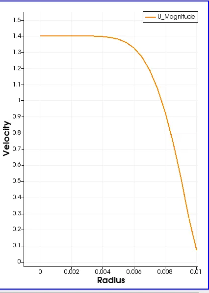
It is observed that when the fluid enters the pipe, the velocity profile about the y-axis gradually changes from a straight line to a parabola due to attraction between fluid and pipe walls and the fluid itself (viscosity). The region where this transition of velocity profile occurs is known as the hydrodynamic entrance region. The span of this region begins from the pipe entrance and ends when the flow is fully developed. This length is known as hydrodynamic entrance length. It is a function of Reynold's Number and is calculated with different formulae for different types of flow.
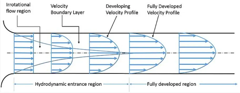
Hagen-Poiseuille's equation is defined to determine the pressure drop in an incompressible fluid laminar flow through the cylindrical pipe. This equation is derived based on the assumption that the pressure drop across the pipe causes due to the viscous force ( resistance force ) acting on the fluid in the opposite direction of the flow.
Assumption & Calculation
In this project, we assume pipe dimension as
Pipe Length (L) = 3 m
Pipe Diameter (d) = 20 mm
And Working fluid as water (liquid) at temperature `25^oC` with
Density `rho` = 1000 kg/m3 and
Dynamic viscosity `mu` = 8.9E-4 Pa-s.
Since the flow is Laminar flow
Reynold’s Number (Re) = 2100
Hydrodynamic Entrance Length is calculated
`L_h = 0.06 . Re.d`
we get `L_h` = 2.52 m
Using the relation between Reynold’s number and average velocity,
`Re = (rho.v_(avg) . d) / mu`
we calculated the average velocity `v_(avg)` = 0.0935 m/s
Maximum velocity `v_(max) = 2*v_(avg)`
`v_(max)` = 0.1869 m/s
Hagen-Poiseullie’s Equation is given as
`Delta P = Q.R`
where , `Delta P` is the pressure drop across the pipe.
Q is flow rate. `Q = A.v_(avg) = pi.R^2.v_(avg)`
and R is resistivity of flow due to viscous flow
`R = (8.mu.L) / (pi.R^4.rho)`
On simplifying the equation
`Delta p = (8.v_(avg).mu.L)/(rho.R^2)`
where `Delta p` is kinematic pressure drop. `Delta p= (Delta P) / rho`
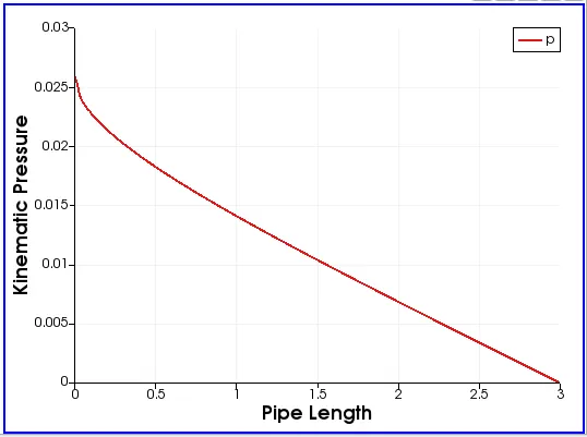
So calculated kinematic pressure drop is `Delta p`= 0.02 N-m/kg
Maximum wall shear stress can be calculated as
`tau_(max) = mu. (v_(max)) / r_h`
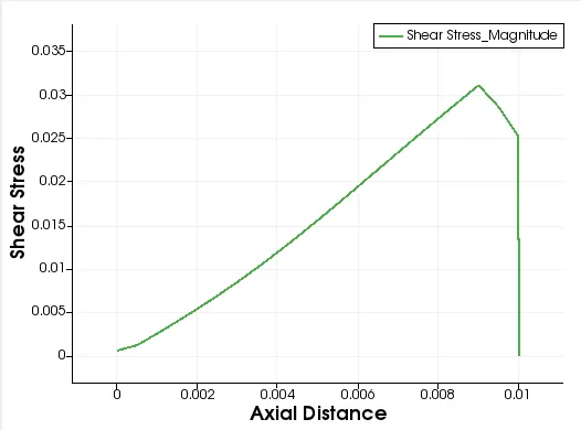
`tau_(max) = 0.0166 N//m^2`
Program Files
MATLAB File
Following is the MATLAB script to create blockMeshDict file
close all
clear all
clc
% Assumed Values
L=3; % Length of the Pipe
d=0.02; % Diameter Of the Pipe
r=d/2; % Radius of the Pipe
theta=3; % Wedge angle
x= r*sind(theta/2); % X co-ordinate
y= r*cosd(theta/2); % Y co-ordinate
nx=20; % No. of cells in x-direction
ny=1; % No. of cells in y-direction
nz=200; % No. of cells in y-direction
gfx = 1 ; % Grading Factor in x-direction
gfy = 1/2; % Grading Factor in y-direction
gfz = 1 ; % Grading Factor in z-direction
l(1) = "/*--------------------------------*- C++ -*----------------------------------*\";
l(2) = " ========= | ";
l(3) = " \\ / F ield | OpenFOAM: The Open Source CFD Toolbox ";
l(4) = " \\ / O peration | Website: https://openfoam.org ";
l(5) = " \\ / A nd | Version: 8 ";
l(6) = " \\/ M anipulation | ";
l(7) = "\*---------------------------------------------------------------------------*/";
l(8) = "FoamFile ";
l(9) = "{ ";
l(10)= " version 2.0; ";
l(11)= " format ascii; ";
l(12)= " class dictionary; ";
l(13)= " object blockMeshDict; ";
l(14)= "} ";
l(15)= "// * * * * * * * * * * * * * * * * * * * * * * * * * * * * * * * * * * * * * //";
l(16)= " ";
l(17)= "convertToMeters 1; ";
l(18)= " ";
% Vertices
l(19)= "vertices ";
l(20)= "( ";
l(21)= sprintf('(0 0 0) // vertice 0'); % Vertices 0 (0 0 0)
l(22)= sprintf('(%f %f 0) // vertice 1',x,y); % Vertices 1 (x y 0)
l(23)= sprintf('(%f %f 0) // vertice 2',-x,y); % Vertices 2 (-x y 0)
l(24)= sprintf('(%f %f %f) // vertice 3',0,0,L); % Vertices 3 (0 0 L)
l(25)= sprintf('(%f %f %f) // vertice 4',x,y,L); % Vertices 4 (x y L)
l(26)= sprintf('(%f %f %f) // vertice 5',-x,y,L); % Vertices 5 (-x y L)
l(27)=" ); ";
% Hexagonal Block
l(28)="blocks ";
l(29)="( ";
l(30)= sprintf(' hex (0 1 2 0 3 4 5 3)(%d %d %d) simpleGrading (%d %1.1f %d)',nx,ny,nz,gfx,gfy,gfz);
% hex (0 1 2 0 3 4 5 3) (nx ny nz) simpleGrading (gfx,gfy,gfz)
l(31)=" ); ";
% Edges
l(32)="edges ";
l(33)="( ";
l(34)= sprintf(' arc 1 2 (0 %2.2f 0)',r); % Arc Formation
l(35)= sprintf(' arc 4 5(0 %2.2f %2.2f)',r,L); % Arc Formation
l(36)="); ";
l(37)=" boundary ";
l(38)=" ( ";
l(39)=" Inlet ";
l(40)=" { ";
l(41)=" type patch; ";
l(42)=" faces ";
l(43)=" ( ";
l(44)=" (0 1 2 0) ";
l(45)=" ); ";
l(46)=" ";
l(47)=" } ";
l(48)=" Outlet ";
l(49)=" { ";
l(50)=" type patch; ";
l(51)=" faces ";
l(52)=" ( ";
l(53)=" (3 4 5 3) ";
l(54)=" ); ";
l(55)=" } ";
l(56)=" wedge1 ";
l(57)=" { ";
l(58)=" type wedge; ";
l(59)=" faces ";
l(60)=" ( ";
l(61)=" (0 3 4 1) ";
l(62)=" ); ";
l(63)=" } ";
l(64)=" wedge2 ";
l(65)=" { ";
l(66)=" type wedge; ";
l(67)=" faces ";
l(68)=" ( ";
l(69)=" (0 3 5 2) ";
l(70)=" ); ";
l(71)=" } ";
l(72)=" upperWall ";
l(73)=" { ";
l(74)=" type wall; ";
l(75)=" faces ";
l(76)=" ( ";
l(77)=" (4 5 2 1) ";
l(78)=" ); ";
l(79)=" } ";
l(80)=" ) ";
l(81)=" mergePatchPairs ";
l(82)=" ( ";
l(83)=" ); ";
l(84)=" ";
l(85)=" // ************************************************************************* // ";
s=size(l);
% blockMeshDict File
blockMeshDict=fopen('blockMeshDict','w');
for i=1:s(2)
fprintf(blockMeshDict,'%s \n',l(i));
end
fclose(blockMeshDict)
OpenFOAM File
1)BlockMeshDict
/*--------------------------------*- C++ -*----------------------------------*\
  =========                 |
  \\      /  F ield         | OpenFOAM: The Open Source CFD Toolbox
   \\    /   O peration     | Website:  https://openfoam.org
    \\  /    A nd           | Version:  8
     \\/     M anipulation  |
\*---------------------------------------------------------------------------*/
FoamFile
{
    version     2.0;
    format      ascii;
    class       dictionary;
    object      blockMeshDict;
}
// * * * * * * * * * * * * * * * * * * * * * * * * * * * * * * * * * * * * * //

convertToMeters 1;

vertices
(
(0 0 0)     // vertice 0
(0.000262 0.009997 0)   // vertice 1
(-0.000262 0.009997 0)   // vertice 2
(0.000000 0.000000 3.000000)  // vertice 3
(0.000262 0.009997 3.000000)  // vertice 4
(-0.000262 0.009997 3.000000)  // vertice 5
 );
blocks
(
  hex (0 1 2 0 3 4 5 3)(20 1 200) simpleGrading (1 0.5 1)
 );
edges
(
 arc 1 2 (0 0.01 0)
 arc 4 5(0 0.01 3.00)
);
 boundary
  (
   Inlet
    {
        type patch;
        faces
        (
         (0 1 2 0)
        );

    }
  Outlet
    {
        type patch;
        faces
        (
         (3 4 5 3)
        );
    }
    wedge1
    {
        type wedge;
        faces
        (
         (0 3 4 1)
        );
    }
    wedge2
    {
        type wedge;
        faces
        (
         (0 3 5 2)
        );
    }
    upperWall
    {
        type wall;
        faces
        (
         (4 5 2 1)
        );
    }
  )
 mergePatchPairs
  (
  );

 // ************************************************************************* //
2) Velocity U
/*--------------------------------*- C++ -*----------------------------------*\
  =========                 |
  \\      /  F ield         | OpenFOAM: The Open Source CFD Toolbox
   \\    /   O peration     | Website:  https://openfoam.org
    \\  /    A nd           | Version:  8
     \\/     M anipulation  |
\*---------------------------------------------------------------------------*/
FoamFile
{
    version     2.0;
    format      ascii;
    class       volVectorField;
    object      U;
}
// * * * * * * * * * * * * * * * * * * * * * * * * * * * * * * * * * * * * * //

dimensions      [0 1 -1 0 0 0 0];

internalField   uniform (0 0 0);

boundaryField
{
      Inlet
    {
        type            fixedValue;
        value           uniform (0 0 0.0935);
    }

    Outlet
    {
        type            zeroGradient;
    }

    wedge1
    {
        type            wedge;
    }

    wedge2
    {
        type            wedge;
    }

    upperWall
    {
         type           noSlip;
    }


}

// ************************************************************************* //
3)Pressure p
/*--------------------------------*- C++ -*----------------------------------*\
  =========                 |
  \\      /  F ield         | OpenFOAM: The Open Source CFD Toolbox
   \\    /   O peration     | Website:  https://openfoam.org
    \\  /    A nd           | Version:  8
     \\/     M anipulation  |
\*---------------------------------------------------------------------------*/
FoamFile
{
    version     2.0;
    format      ascii;
    class       volScalarField;
    object      p;
}
// * * * * * * * * * * * * * * * * * * * * * * * * * * * * * * * * * * * * * //

dimensions      [0 2 -2 0 0 0 0];

internalField   uniform 0;

boundaryField
{
    Inlet
    {
        type            zeroGradient;
    }

    Outlet
    {
        type            fixedValue;
        value           uniform 0;
    }

    upperWall
    {
        type            zeroGradient;
    }

    wedge1
    {
        type            wedge;
    }

    wedge2
    {
        type            wedge;
    }

}


// ************************************************************************* //
3) transportProperties
/*--------------------------------*- C++ -*----------------------------------*\
  =========                 |
  \\      /  F ield         | OpenFOAM: The Open Source CFD Toolbox
   \\    /   O peration     | Website:  https://openfoam.org
    \\  /    A nd           | Version:  8
     \\/     M anipulation  |
\*---------------------------------------------------------------------------*/
FoamFile
{
    version     2.0;
    format      ascii;
    class       dictionary;
    location    "constant";
    object      transportProperties;
}
// * * * * * * * * * * * * * * * * * * * * * * * * * * * * * * * * * * * * * //

nu              [0 2 -1 0 0 0 0] 8.9e-7;


// ************************************************************************* //
4) controlDict
/*--------------------------------*- C++ -*----------------------------------*\
  =========                 |
  \\      /  F ield         | OpenFOAM: The Open Source CFD Toolbox
   \\    /   O peration     | Website:  https://openfoam.org
    \\  /    A nd           | Version:  8
     \\/     M anipulation  |
\*---------------------------------------------------------------------------*/
FoamFile
{
    version     2.0;
    format      ascii;
    class       dictionary;
    location    "system";
    object      controlDict;
}
// * * * * * * * * * * * * * * * * * * * * * * * * * * * * * * * * * * * * * //

application     icoFoam;

startFrom       startTime;

startTime       0;

stopAt          endTime;

endTime         20;

deltaT          0.01;

writeControl    timeStep;

writeInterval   20;

purgeWrite      0;

writeFormat     ascii;

writePrecision  6;

writeCompression off;

timeFormat      general;

timePrecision   6;

runTimeModifiable true;


// ************************************************************************* //
Results
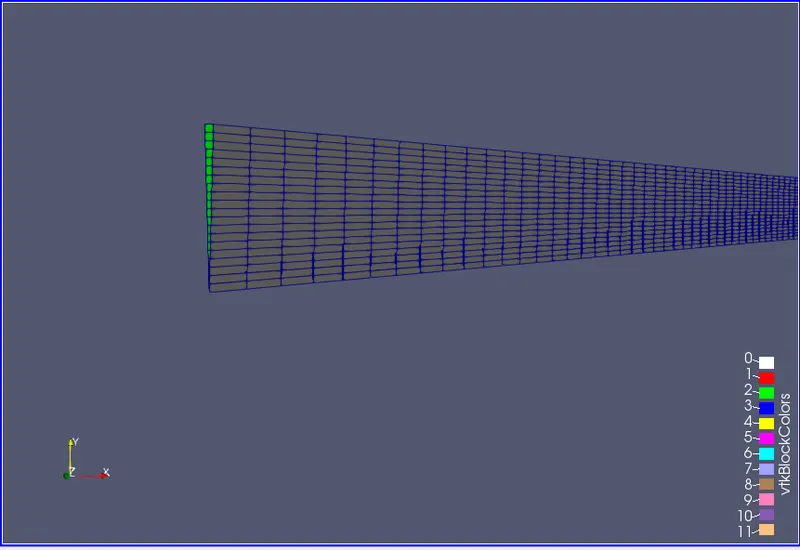
Block of wedge angle `3^o`.
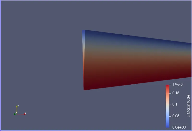
Velocity Contour
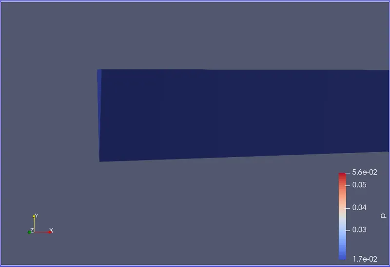
Pressure Contour
Graphs
Velocity Profile
Velocity Profile at x= 0.1m (Under Developed)
Velocity Profile at x= 0.5m (Under Developed)
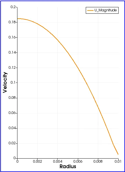
Velocity Profile at x= 2.52m (Fully Developed)
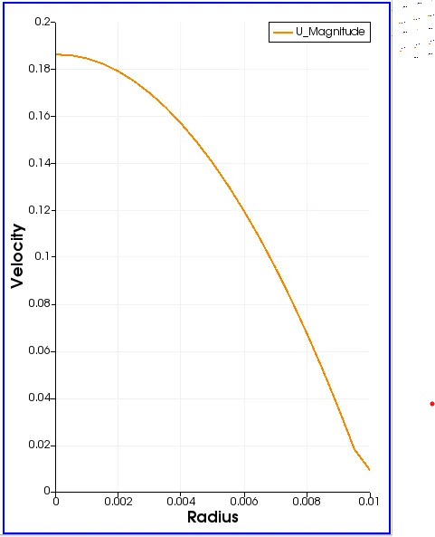
Velocity Profile at x= 5m (Fully Developed)
Kinematic Pressure drop along the pipe length
Wall Shear Stress
Comparision
| Result | Maximum Velocity | Pressure Drop | Maximum Shear Stress |
| Simulation Result | 0.1876 | 0.0259 | 0.0302 |
| Theoretical Result | 0.1869 | 0.02 | 0.0332 |
Conclusion
1) We calculated the hydrodynamic entrance length which is 2.52 m from the pipe entrance. It can be observed from the velocity profile graphs obtain from the simulation that the flow become fully developed after 2.52m
2) It is observed that the velocity profile curve obtained from simulation in the fully developed region is parabolic.
3) From the above comparison table it can be concluded that numerical results obtained from the simulation are approximately equal to the theoretical results obtain from the calculation.