Week 6 - CHT Analysis on a Graphics card
CONJUGATE HEAT TRANSFER ANALYSIS ON GRAPHICS CARD
Aim:
To simulate and analyze the conjugate steady-state heat transfer on a graphic card using ANSYS Fluent.
Objective:
-To simulate CHT for the velocity of 1m/s 3m/s and 5m/s.
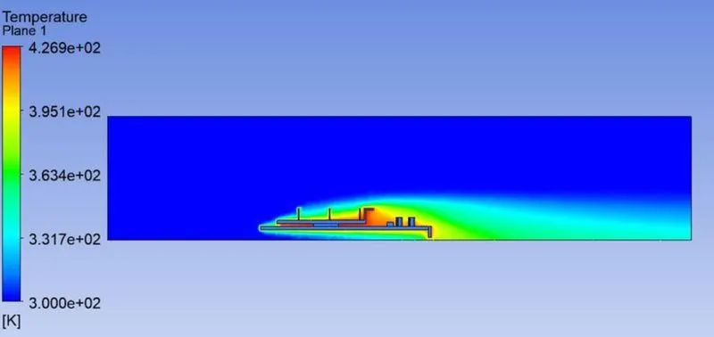
-To find the maximum temperature attained by the processor.
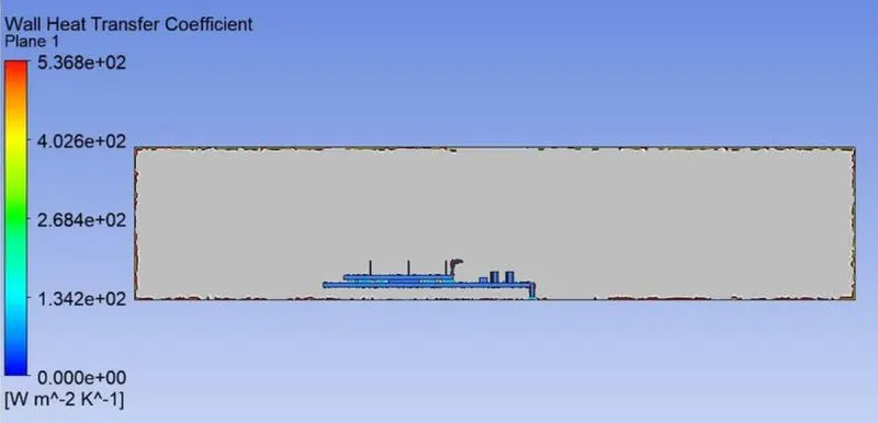
-Find out the heat transfer coefficient of the processor.
-To identify the potential hotspots on the model.
Introduction:
Graphics card has become the essential components in modern-day laptops and computer systems. Earlier, graphic cards were used to produce a feed of output images to the display devices. But they are not limited to displaying output as they are capable of performing additional processing. Nowadays graphic card is used extensively for high-performance computing and parallel computing for computer simulation, cryptocurrency mining, AI training, etc.
Graphics cards consume electricity to operate and generate a huge amount of heat. To avoid failure and damage to the graphics card and computer system because of heat generated, it is necessary to cool the graphics card.
There are various techniques for cooling such electrical components including various styles of heat sinks, thermoelectric coolers, forced air systems and fans, heat pipes, etc.
Usually, graphics cards are cooled by placing a heat sink such as fins with higher heat capacity on the processor and forced air blown over the fins. It works on the principles of conjugate heat transfer.
Conjugate heat transfer refers to the combination of conductive heat transfer in solids and convective heat transfer in the fluid.
In the current project, we will be simulating CFD analysis on graphics cards where the processor acts as the heat source, fins as heat sinks, and forced air blown over the graphics card placed in an enclosure.
Procedure:
Workbench Project:
-Open ANSYS Workbench and drag and drop Fluent.
-Click on File and save the project as “CHT_Graphics_Card”.
Geometry:
-Open ANSYS Space Claim and import the downloaded geometry.
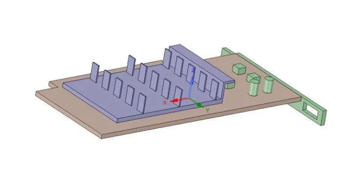 |
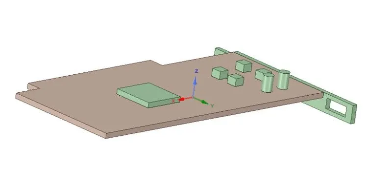 |
| fig.Graphics card with fin | fig. The processor under the fins |
-Create an enclosure over the model which acts as a wind tunnel.

-Make sure to check the shared topology to avoid the formation of non-conformal mesh.
-Click on File and save the project.
Meshing:
-Open ANSYS Meshing and specify the name for all the parts/components.
-Click on generate mesh to create a baseline mesh. This baseline mesh is used for the grid test.
-Create a refined mesh where each component has a different element size.
-Since most of the heat transfer takes place in the processor and the fins, the element size of mesh for the processor and the fins is 5e-4m whereas, for the remainings, it will be 3e-3m.
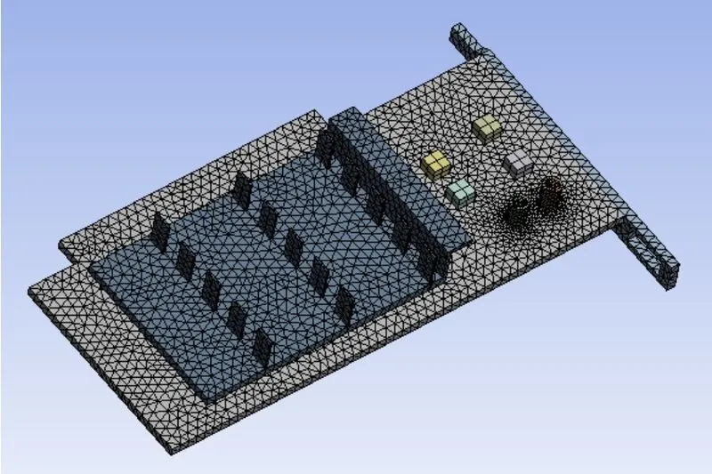
-Save the project.
Setup:
-Open ANSYS Fluent and set up the simulation as mentioned below.
- Solver Type: Pressure-Based Steady State simulation
-Check the Energy Equation
-Viscous Model: k-omega SST model
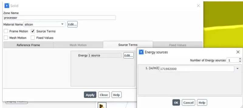
-Since the processor acts as the heat source, specify the calculated heat generated.
-For this simulation, let’s assume that the processor consumes 75W of energy and converts all of it into heat. The dimensions of the processor are 8mm x 8mm x 1mm.
Then the heat generated per volume will be
`75/(8**8**1)**10^9 = 1.17**10^9 W/(m^^3)`
-Material type:
| Components | Material |
Density (kg/m^3) |
Heat Capacity (J/kg-K) |
Thermal Conductivity (W/m-K) |
|
Base |
FR4(Created) | 1850 | 950 | 0.29 |
| Processor |
Silicon(Created) |
2000 | 710 | 150 |
| Fin |
Aluminum |
2719 | 871 | 202.4 |
| Enclosure |
Air |
1.225 | 1006.43 | 0.0242 |
-We have split this project into three cases for different inlet velocities: 1m/s, 3m/s, and 5m/s.
Results:
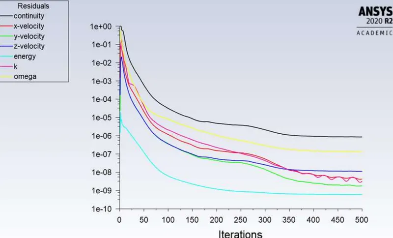
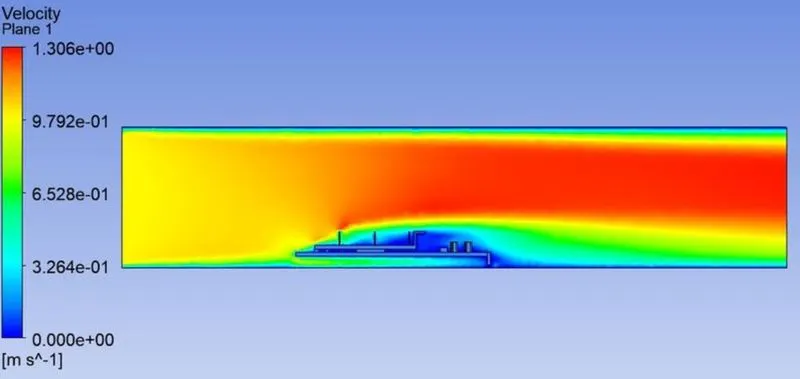
Case 1: 1 m/s
Residual
Temperature Contour
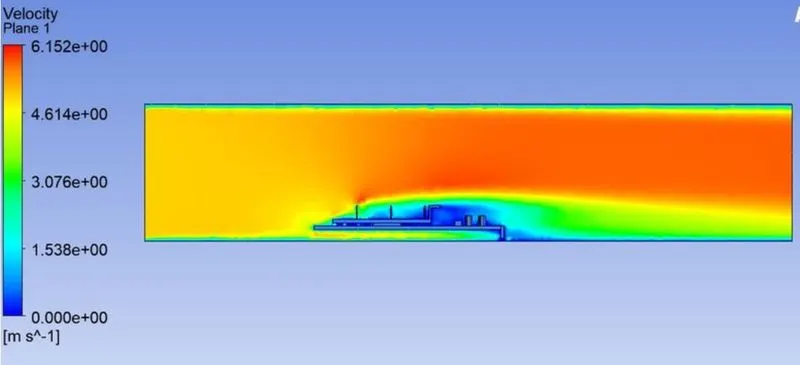
Velocity Contour
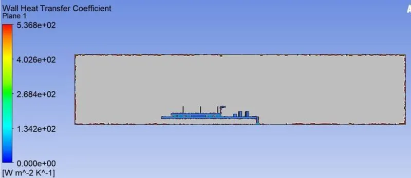
Wall Heat Transfer Coefficient
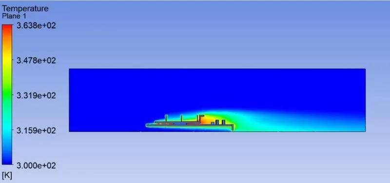
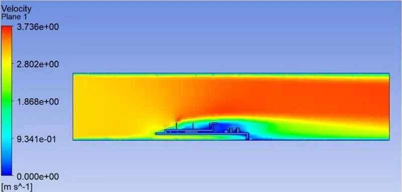
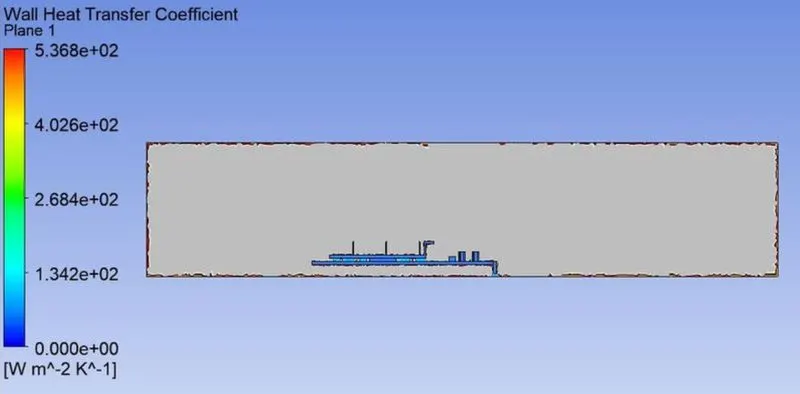
Case 2: 3 m/s
Residual
Temperature Contour
Velocity Contour
Wall Heat Transfer Coefficient
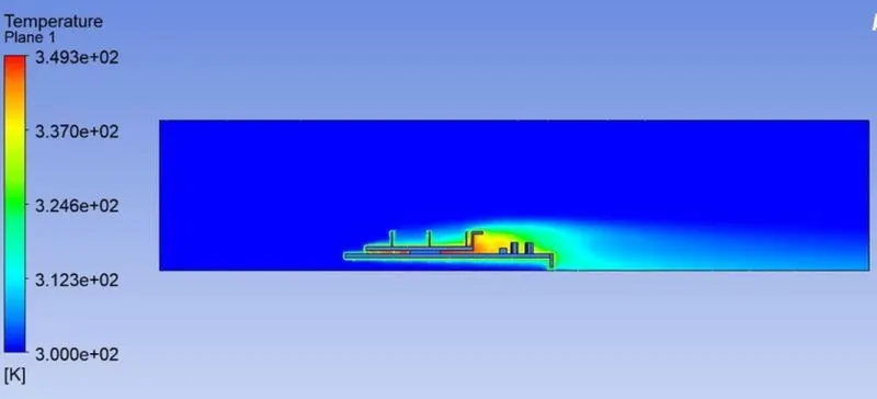
Case 3: 5 m/s
Residual
Temperature Contour
Velocity Contour
Wall Heat Transfer Coefficient
| Inlet Velocity | Max. Temperature of Processor | Max. Temp. of Fins | Heat Transfer Coefficient at fins |
| 1 m/s | 413.06 K | 408.70 K | 505.48 |
| 3 m/s | 368.11 K | 361.51 K | 518.72 |
| 5 m/s | 348.32 K | 340.07 K | 527.56 |
Conclusion:
-Cooling of the processor depends on two factors- fins and inlet velocity.
-Since the fins are made of Aluminum with a heat capacity more than the processor(silicon), there is a better heat transfer rate. Material with higher heat capacity like silver and copper and fins structured with more surface area will enhance the cooling rate of the processor.
-It is observed from the simulation that the processor temperature will be lower for the higher inlet velocity.