Week 3 Challenge : CFD meshing on Turbocharger
CFD meshing on Turbocharger
Aim: To perform CFD meshing of the turbocharger model and to write a detailed report bout the surface meshing and volume meshing procedure.
Procedure:
-Import the model to ANSA.
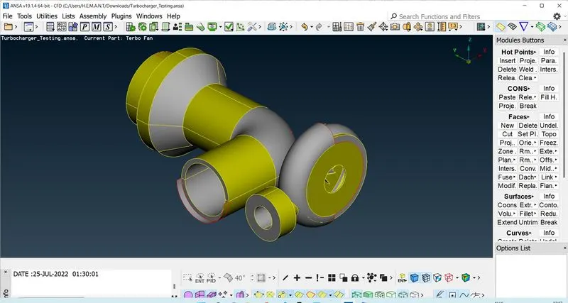
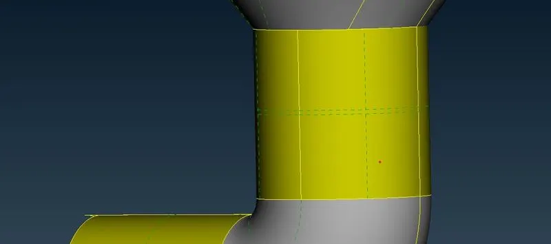
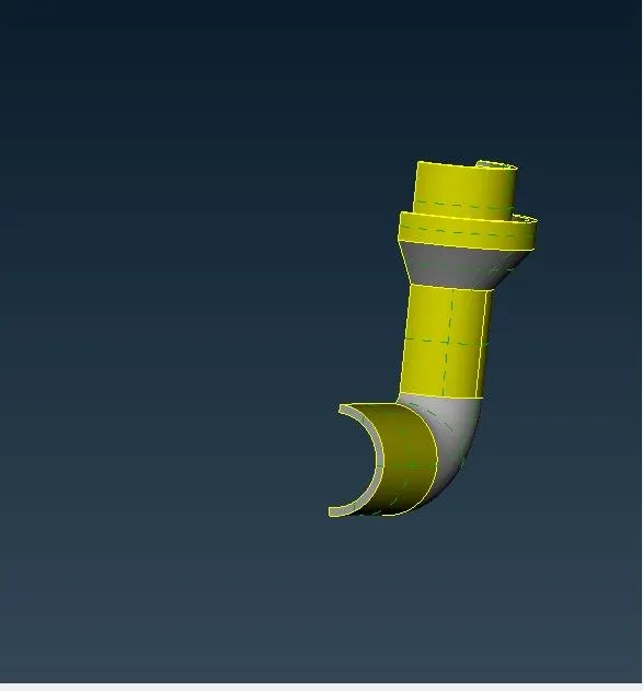
-We found some duplicate surfaces overlapping with other surfaces. It can be identified by observing two cross-hatches on the same surface. Use the Delete option to delete the duplicate surface.
 |
 |
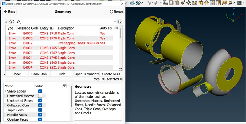
-Check the topological error in the turbocharger model using the Checks Manager option. Most of the errors are due to single cons which are represented with red lines on the model.
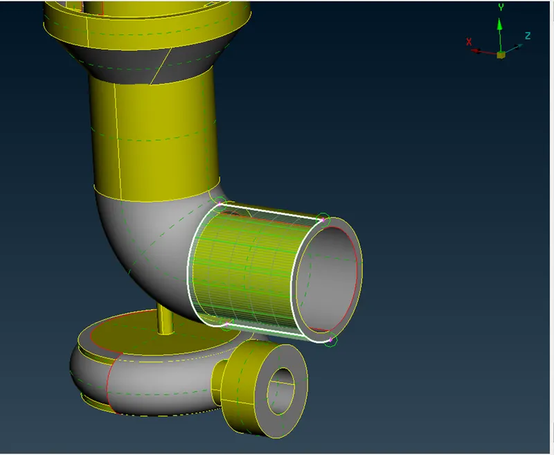
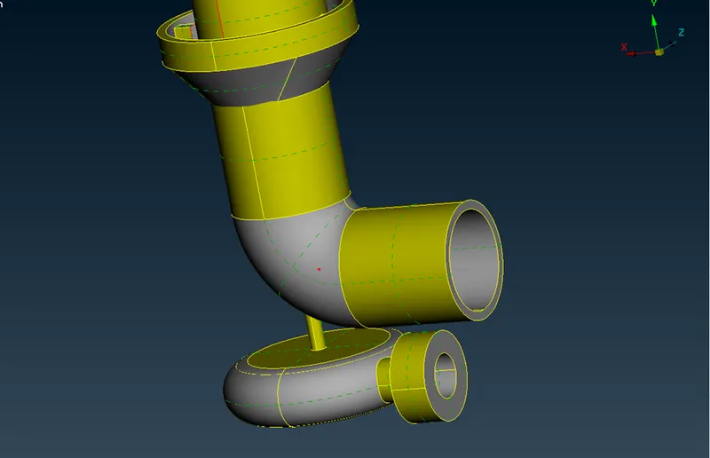
-Delete the extra surface projecting outwards at the inlet and create a new face using the New option in the Face module to create a new face. Also, use the same process for missing faces to create new faces over there.
 |
 |
-In some cases, we will fail to create faces that match the geometry. For such cases, we use different options available in ANSA.
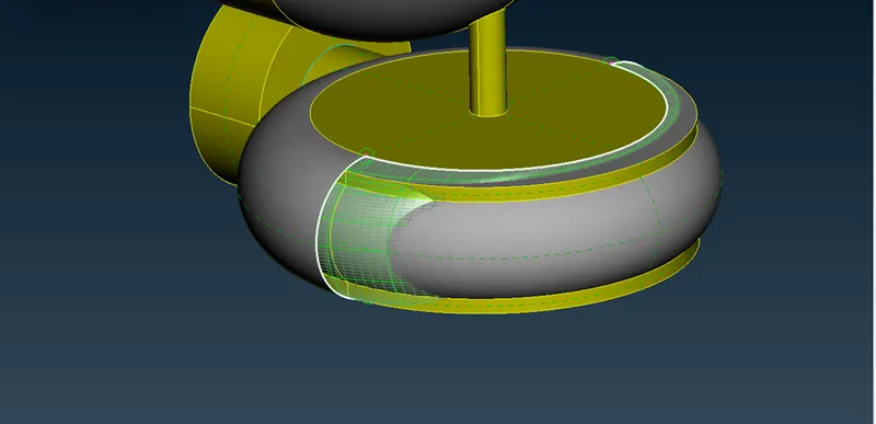
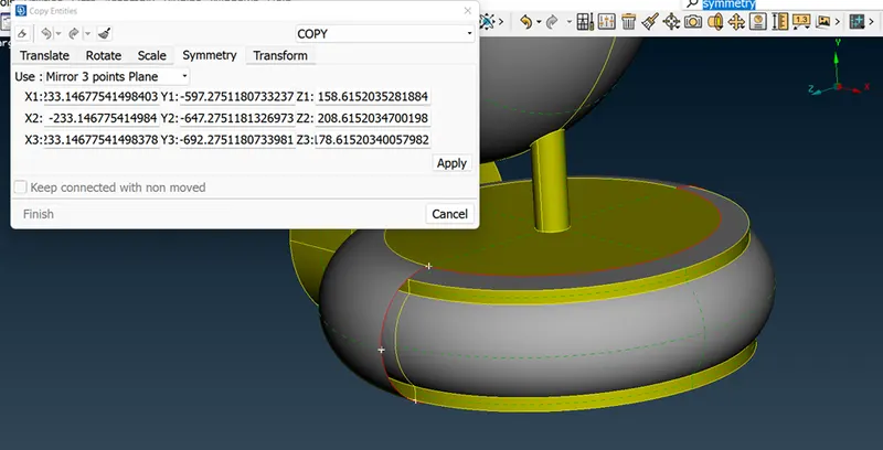
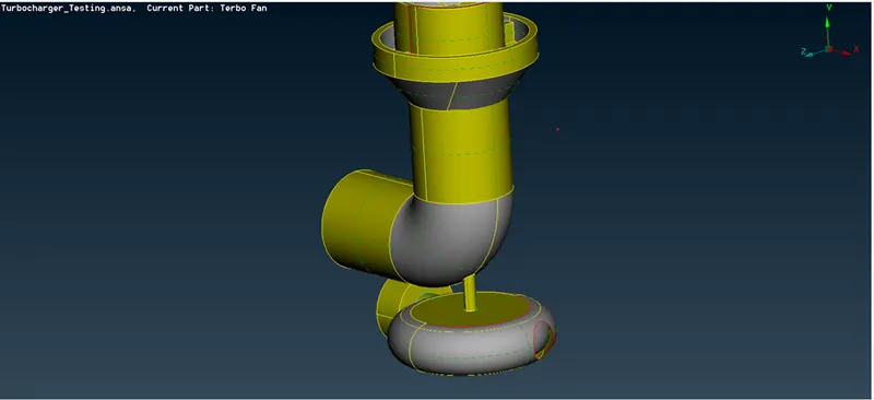
-For the above case, use the Copy option in the Transform module and select the entity to copy. Opt for the symmetry option with a Mirror 3-point plane and select the points on the curve to create a surface in symmetry to that curve as a mirror plane. Middle click to complete the
 |
 |
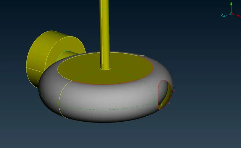
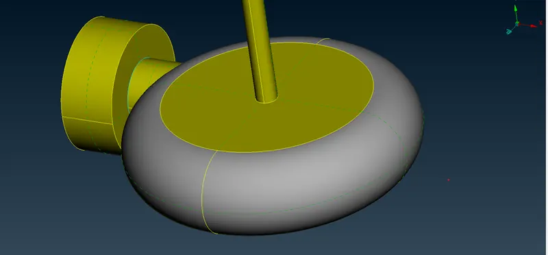
-Use the Fill Hole option to close the hole and the Topo option in the Face module to make the connection between two surfaces.
 |
 |
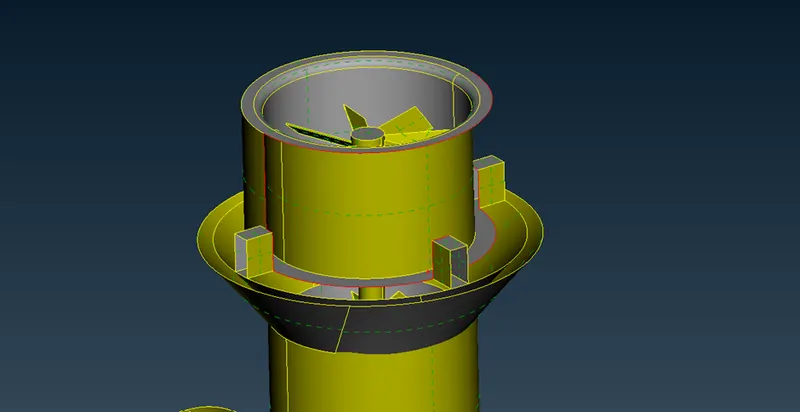
-There is a missing face near the outlet of the exhaust pipe. That surface cannot be directly created.
 |
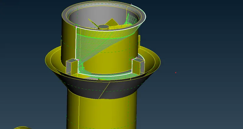 |
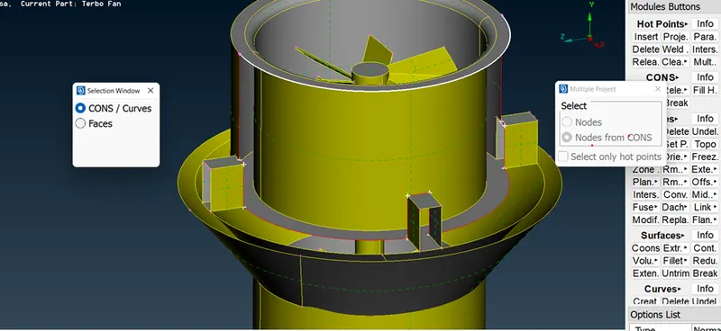
-Instead, we can create multiple faces to cover it. Use the Multi Project option in the Hot Point module to project the points on the upper curve.
 |
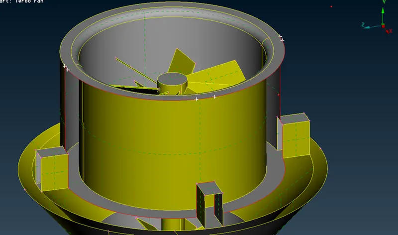 |
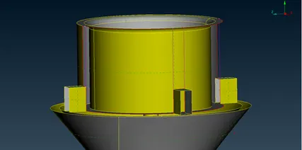
-Use the Create option in the Curve module to create a curve connecting those hot points and create faces through those curves.
 |
 |
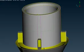 |
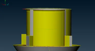
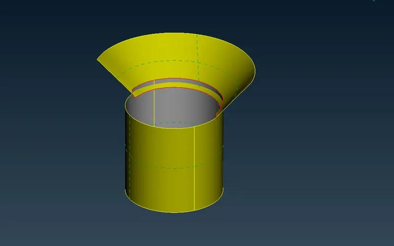
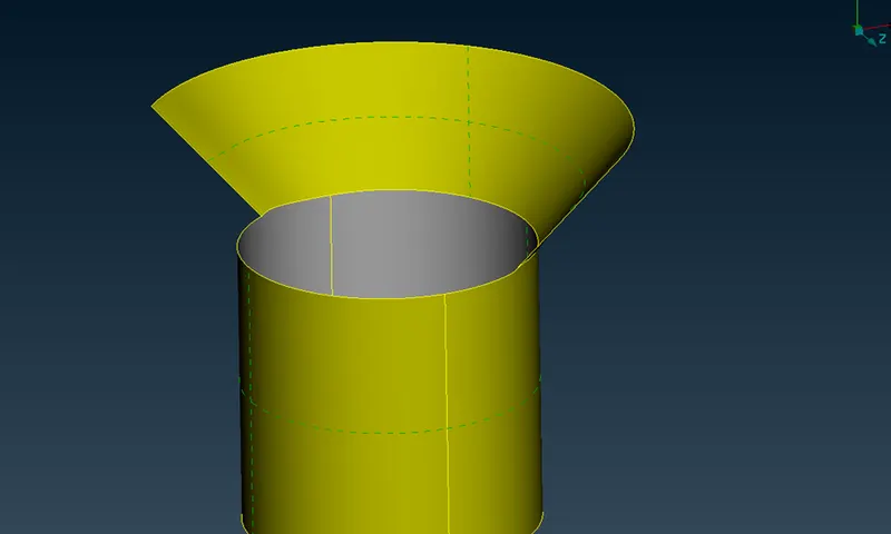
-We also have a few Penetration errors as shown below.
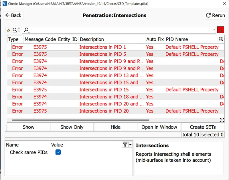
-Assign the PIDs for all the components before fixing the penetration error as it will make the process of rectifying the errors easy.
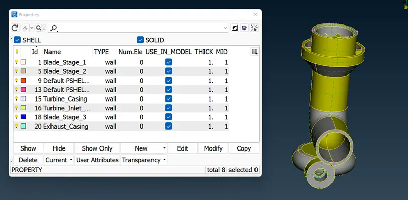
-As shown in the figure below, there is a penetration issue with the component. Use the Intersection option in the Face module and select the surfaces that are needed to intersect. Delete the extra surfaces and use the Topo tool to join the edges
 |
 |
-Similarly, there are penetration issues with many components. Use the Intersection tool in the Face module, delete the extra unnecessary surfaces and use the Topo tool in the Face module to join the edges.
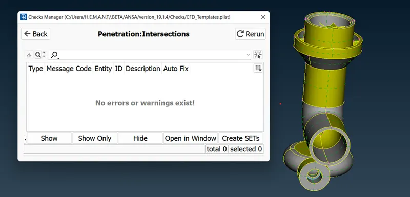
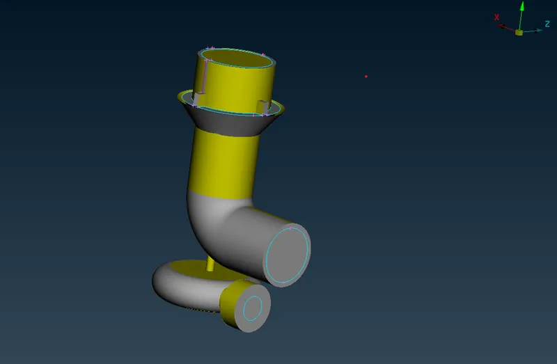
-Close all the open surfaces as we need watertight geometry for volume meshing. Use The Fill Hole tool of the CONS module and the New tool of the Face Module to close the openings. Ignore the triple-cons warning.
Surface Meshing
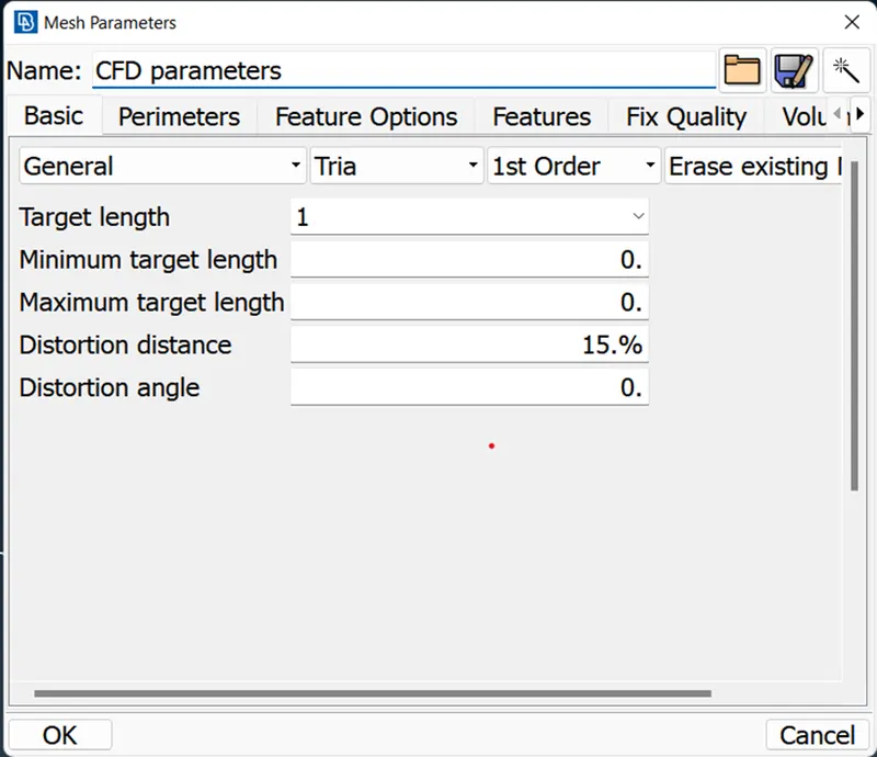
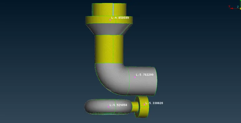
-Perform surface mesh with the given target lengths as per PIDs.
Blade stage-1 = 1 mm
Blade stage-2 = 1 mm
Shaft rotor = 1 mm
Impeller = 2 mm
Turbo casing = 5 mm
Compressor casing = 5 mm
Inlet casing cover = 5 mm
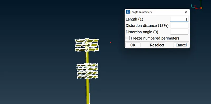
-Individually mesh the component with the above criteria. Use the Length option in the Perimeter module in Mesh Deck to specify the lengths for perimeter and macros. Specify the mesh parameters as mentioned above using the Mesh Parameter option.
 |
 |
-Use the Spot Meshing option in the Mesh Generation module to generate the mesh.
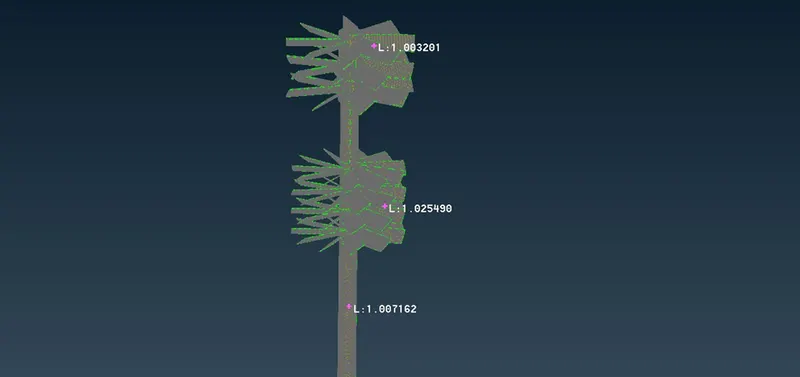
-Since we are meshing different components with different mesh parameters, there is a chance that the mesh of a component influences the mesh of the neighboring component. After meshing the component, use the Freeze option in the Macros module to avoid such errors.
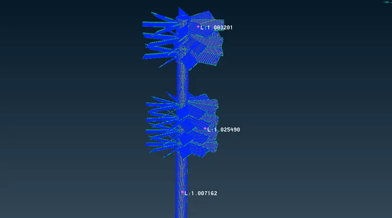
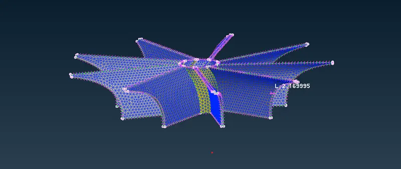
-Repeat the same process of the surface meshing for all the components with the target length as mentioned.
 |
 |
Volume Meshing
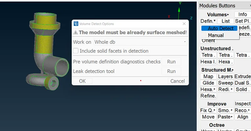
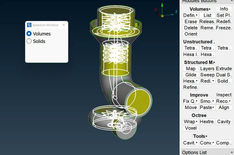
-Use the Define option in the Volume module of the Volume Mesh Deck to define the volume that is to mesh. Opt for the auto-detect option and select the Whole DB to work on.
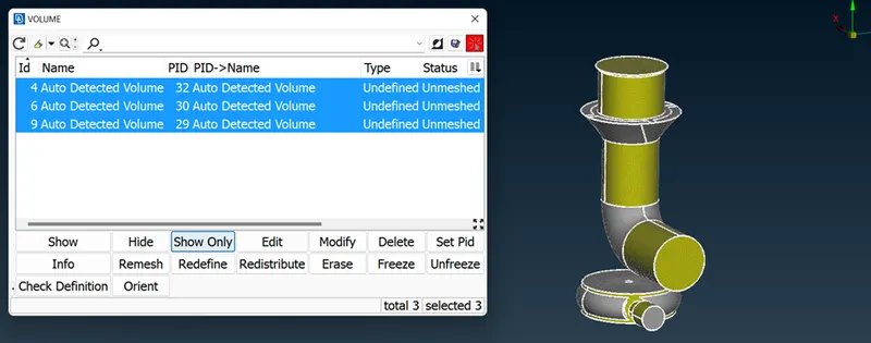
-From the list of auto-detected volumes, delete the solid volumes. Use the Tetra CFD tool in the Unstructured Mesh module and select the volumes for volumetric meshing.
 |
 |
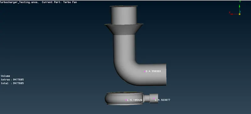
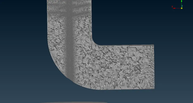
-Volumetric meshed of turbocharges and its cut plane view for the volumetric mesh as shown in the figure below.
 |
 |
Conclusion:
The objective of this project is to check for topological errors and rectify them. Surface meshing and volumetric meshing of the turbocharger model.
Through this project, we learn to use different tools available in ANSA for geometrical clean-up such as the Intersection tool, Release tool, Topo tools, etc.