Week 9 - Parametric study on Gate valve.
PARAMETRIC STUDY ON GATE VALVE
AIM: To perform a parametric study on the gate valve simulation by setting the opening from 10% to 80%.
INTRODUCTION:
Gate Valve:
A gate valve is a valve with a sliding part that opens on lifting the gate disc and closes on lowering the gate disc. Gate is used to shut the fluid flow rather than regulating the flow. Gate valves require very little space along the pipe axis and hardly restrict the flow of fluid when the gate is fully opened.
Flow Coefficient (`C_v`):
The Flow Coefficient describes the relationship between the pressure drop across a valve and the corresponding flow rate. It is defined as the number of U.S. gallons of fluid that can pass through a valve or orifice at a pressure drop of 1 PSI. It acts as an important criterion for selecting the right sized valve for the application s it helps in comparing the different valves and their flow capacity and understanding the effect of the valve on the pressure of the pipe system.
Mathematically, the flow coefficient is expressed as
`C_v = Q*sqrt((SG)/(Delta P))`
Where,
Cv is Flow Coefficient or flow capacity rating,
Q is the flow rate (US gallon per minute),
SG is the specific gravity of the fluid (SG=1 for water),
∆P is pressure drop across the valve (psi),
Flow Factor (`K_v`):
The Flow Factor (`K_v`) is an imperial version of the Flow Coefficient (`C_v`). Mathematically it can be expressed as
`K_v = Q*sqrt((SG)/(Delta P))`
Where,
Kv is Flow Factor,
Q is the flow rate (`m^3/h`),
SG is the specific gravity of the fluid (SG=1 for water),
∆P is pressure drop across the valve (bar),
Following is the relation between Kv and Cv
Kv = 0.865*Cv
SIMULATION MODELLING APPROACH:
- Objective of this study is to analyse the change in mass flow with the opening of the gate valve.
- Lod the gate valve model in SpaceClaim.
- Elongate the gate valve from the inlet and the outlet using the ‘Pull’ option and extract the fluid volume from the solid volume using the ‘Volume Extract’ option.
- Move the gate valve upward using the ‘Move’ option.
- Parametrize the lift of the gate valve. Set the lift as an input parameter.
- Suppress the physics for all the components except extracted fluid volume.
- Create fine mesh for the fluid volume model.
- Setup the fluent with steady-state simulation and gravity enabled.
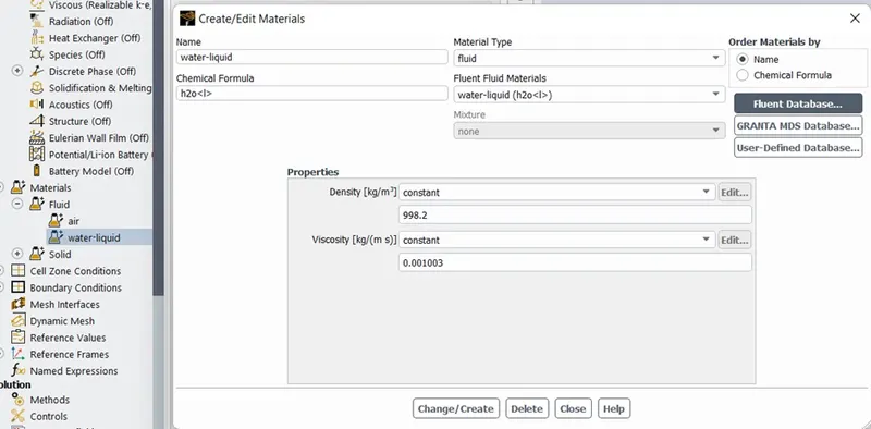
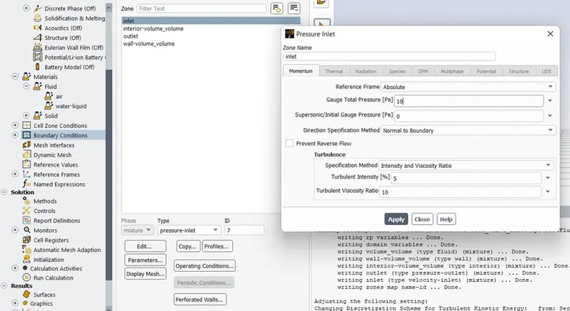
- Set water as fluid in the cell zone with 10 Pa gauge pressure at the inlet.
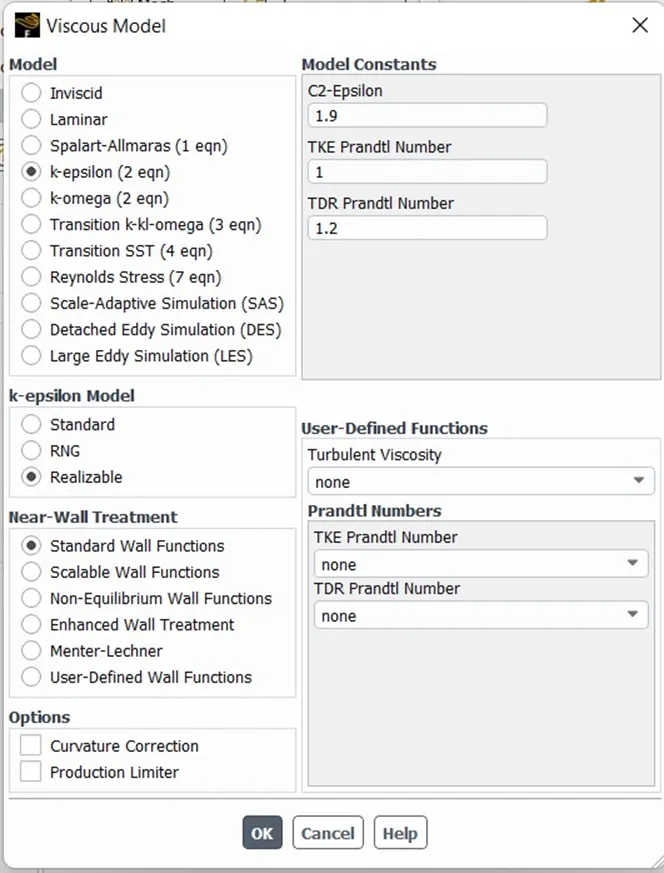
- Since the flow is turbulent, opt for the k-epsilon viscous model with a Realizable Standard Wall Function for Near Wall Treatment.
- Set mass flow rate at the outlet, gauge pressure at inlet and outlet as the output parameter.
PROCEDURE:
Workbench Project:
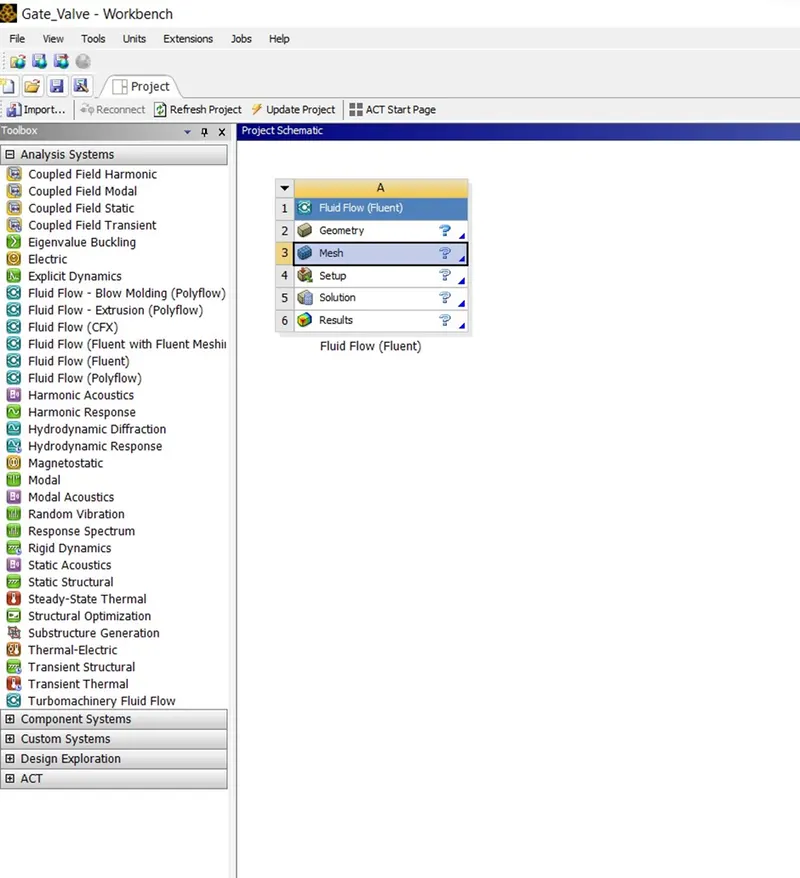
- Open ANSYS Workbench and drag and drop Fluent.
- Click on File and Save the Project as ‘Gate_Valve’.
Geometry:
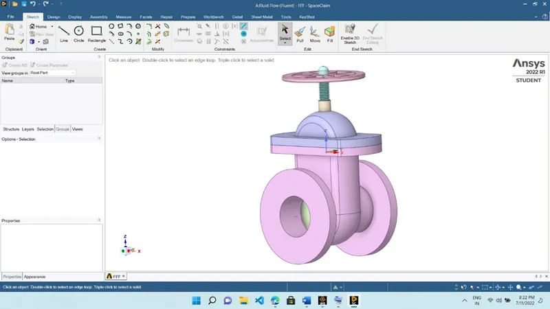
- Open SpaceClaim and import the gate valve model.
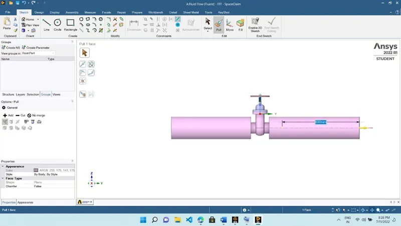
- Elongate the inlet and the outlet up to 800 mm each using the ‘Pull’ command.
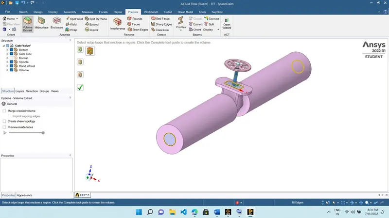
- Extract the fluid volume from the solid model using the ‘Volume Extract’ command. Make sure to hide the Bonnet to select the edge at the top.
- Move the gate valve upward using the ‘Move’ command. Hide the components to make the gate disc visible. Select the gate disc and move it in the upward direction (+ve Z-Direction).
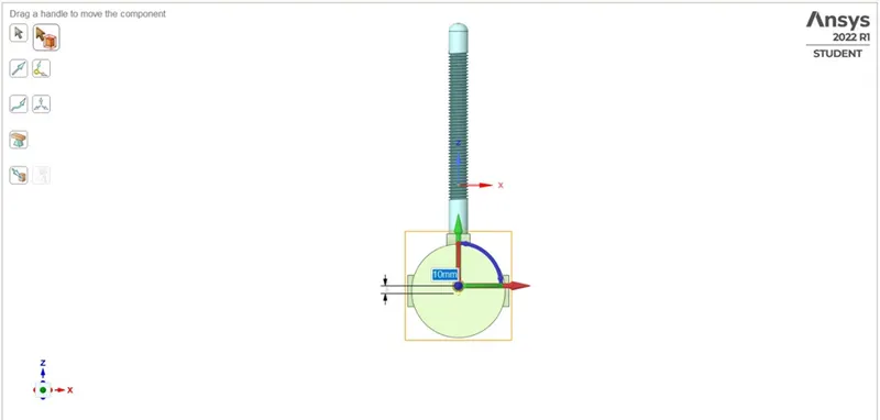
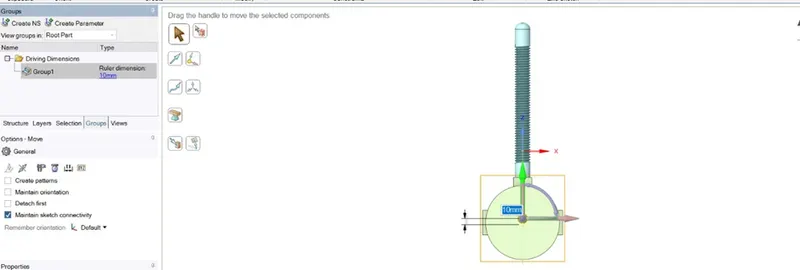
- Click on Groups then click on Create Parameter to parametrize the lift of the gate disc.
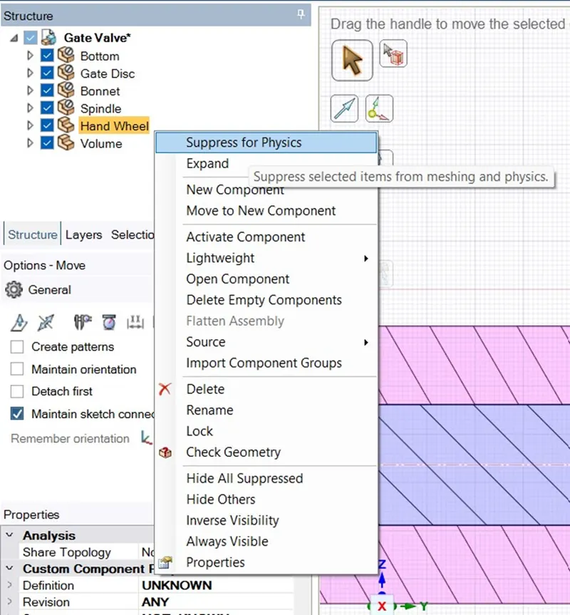
- Suppress the physics for all the components except fluid volume.
- As the gate disc moves upwards, it creates a space as soon as in the figure below.
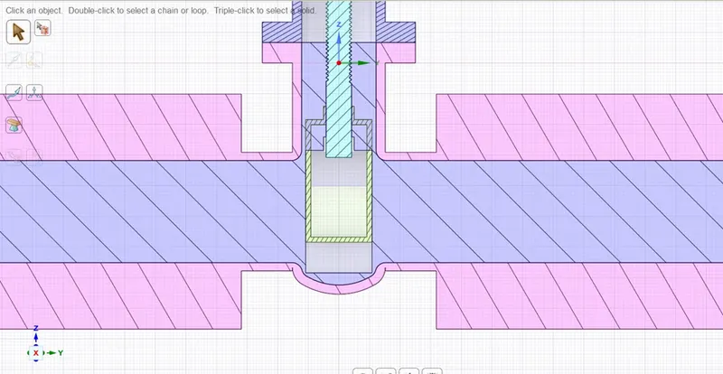
- Right-click on Volume, and click on Update Volume Body in Content to update the fluid volume.
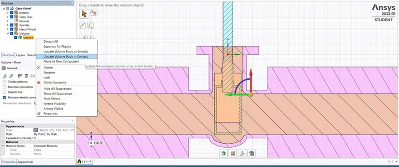
- Note: Hide the Bonnet before moving the gate disc component.
- Click on File and Save the Project.
Meshing:
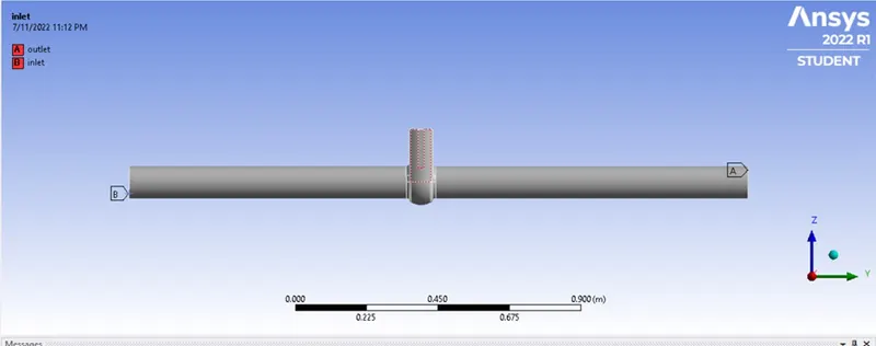
- Open ANSYS Meshing. Select the faces and specify the names as inlet and outlet to the selected faces.
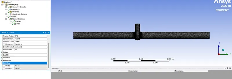
- Generate the mesh with 10mm as element size.
- Click on File and Save the Project.
Fluent Setup:
- Open NSYS Fluent and set up the simulation as mentioned below
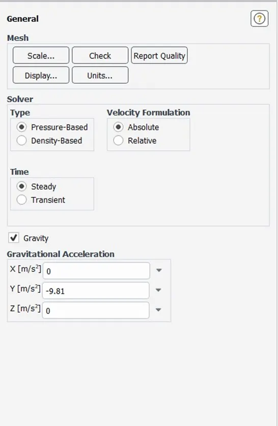
- Check the solver time as Steady
- Check the gravity and specify -9.81 m/s in the Y-direction.
- Select the k-epsilon viscous model with Realizable Standard Wall Function for Near Wall Treatment.
- Click on Material then on Fluid. Copy liquid water from the Fluent Database.
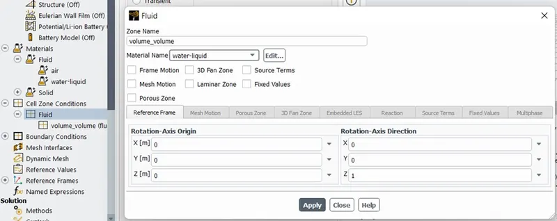
- Set the liquid water as material for the fluid volume zone (cell zone).
- Set up the inlet boundary condition with pressure-inlet type at 10 Pa gauge pressure.
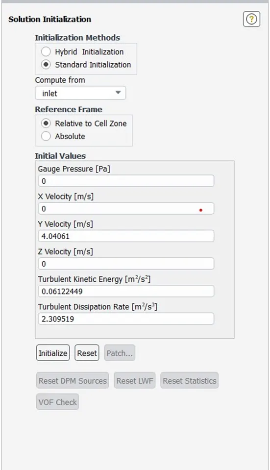
- Initialize the solution with standard initialization compute from the inlet.
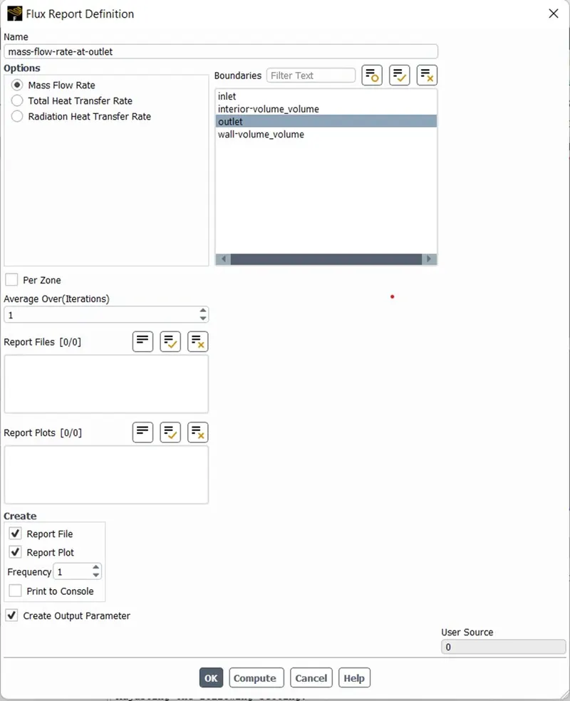
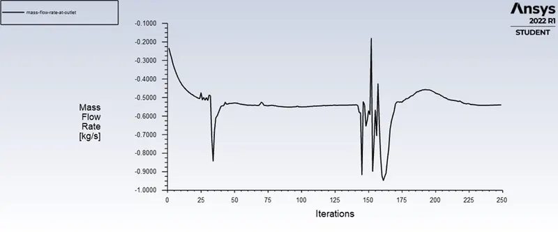
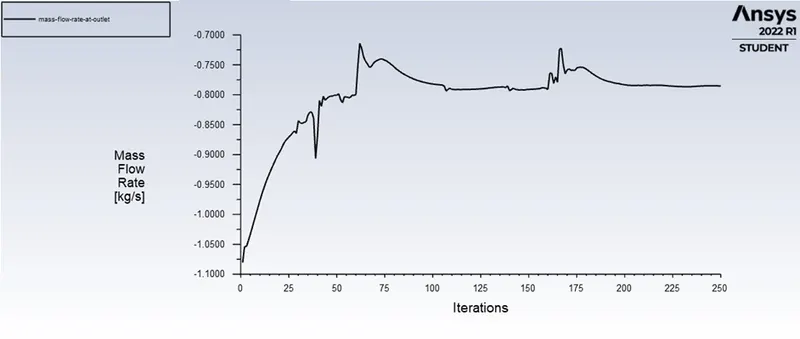
- Create Flux Report Definition for mass flow rate at the outlet. Check the Create Output Parameter box.
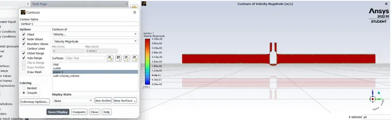
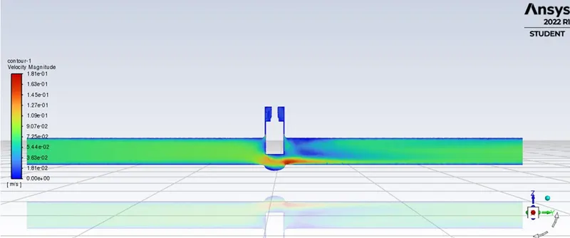
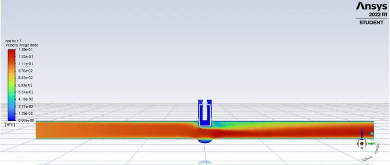
- Create the contour plot of velocity to visualize the flow.
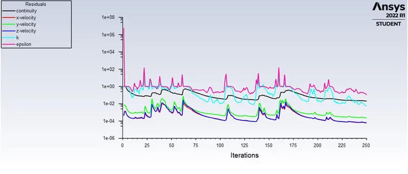
- Run the calculation for 300 iterations.
Parameter Set:
-Since we parametrized the lift of the gate valve disc, add more design points to the parameter set.
- Add points 10mm, 20mm, 30mm, 40mm, 50mm, 60mm, 70mm, 80mm to the input parameter column.
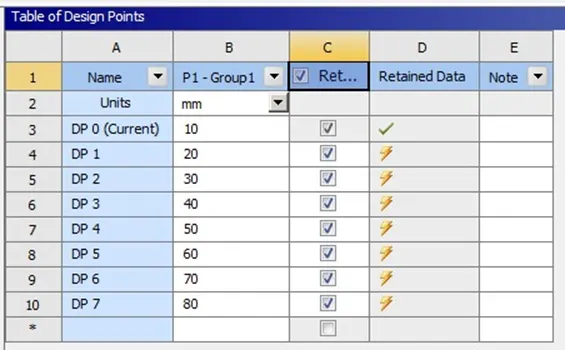
- Click on Update all Design Points to obtain the output parameter i.e. mass flow rate at the outlet for their respective input parameter.
RESULTS:
|
LIFT |
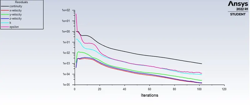
RESIDUAL PLOT |
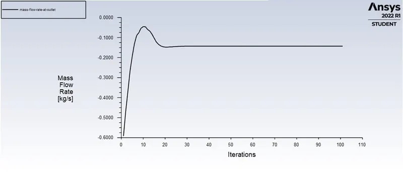
MASS FLOW RATE AT THE OUTLET |
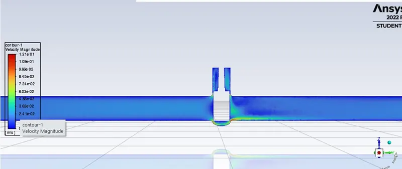
CONTOUR PLOT OF VELOCITY |
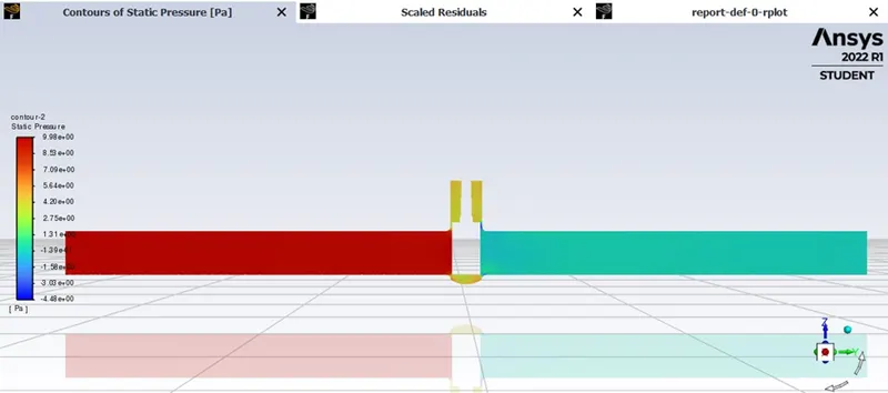
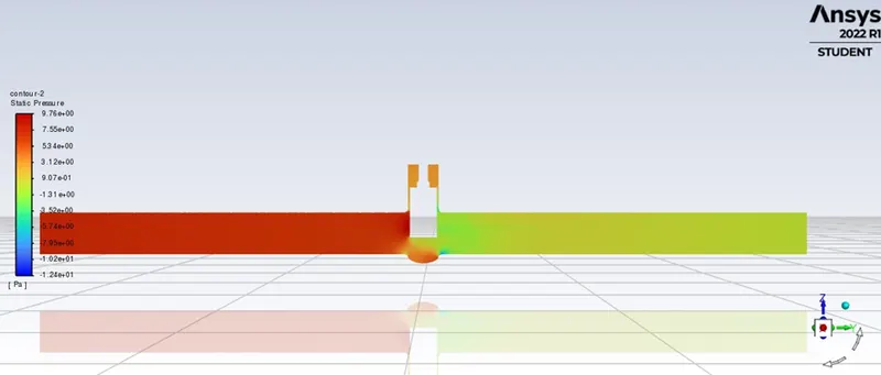
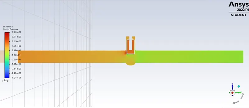
CONTOUR PLOT OF PRESSURE |
|
10mm |
 |
 |
 |
 |
|
20mm |
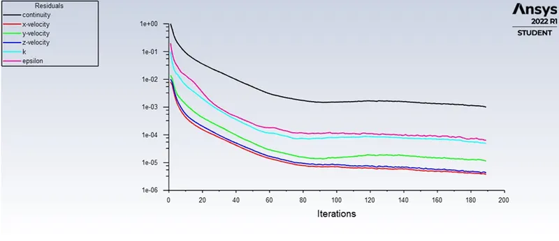 |
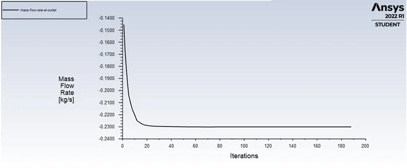 |
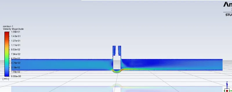 |
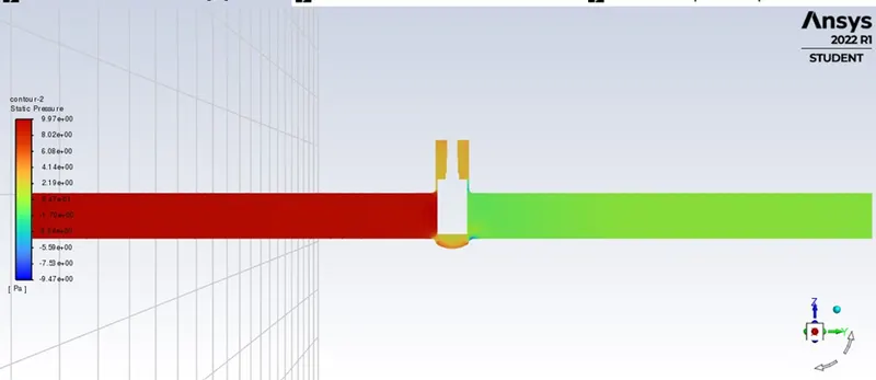 |
|
30mm |
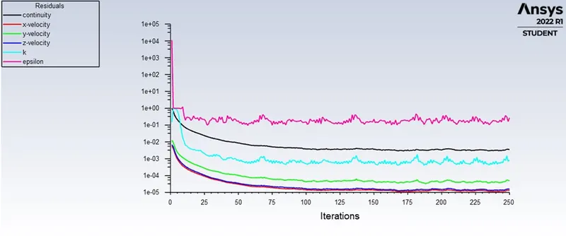 |
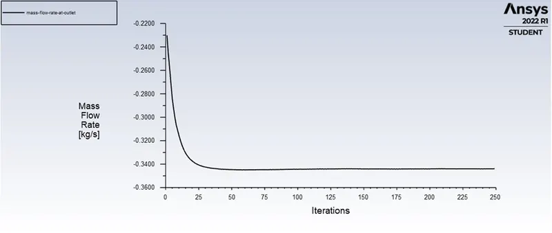 |
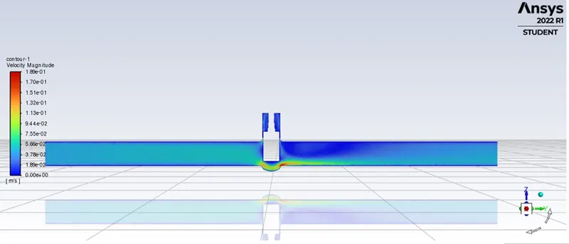 |
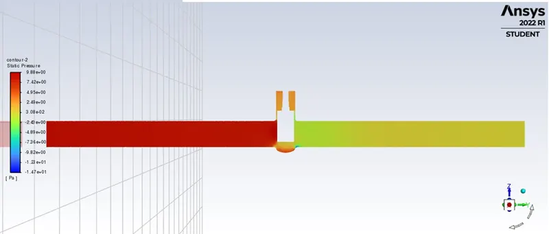 |
|
40mm |
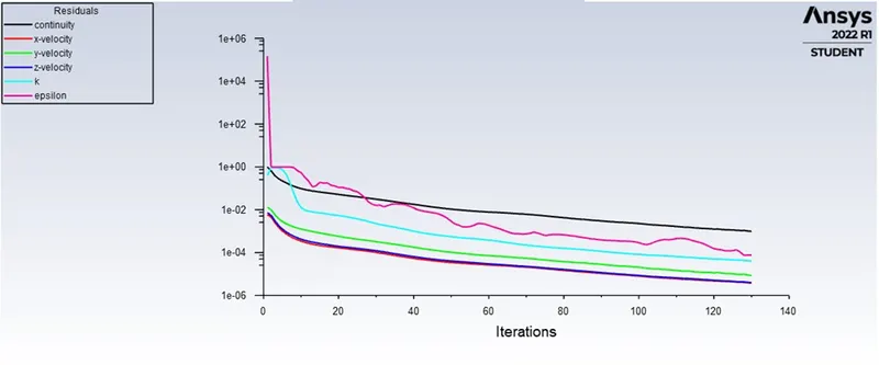 |
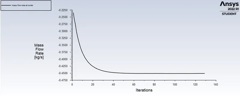 |
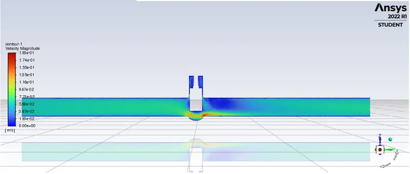 |
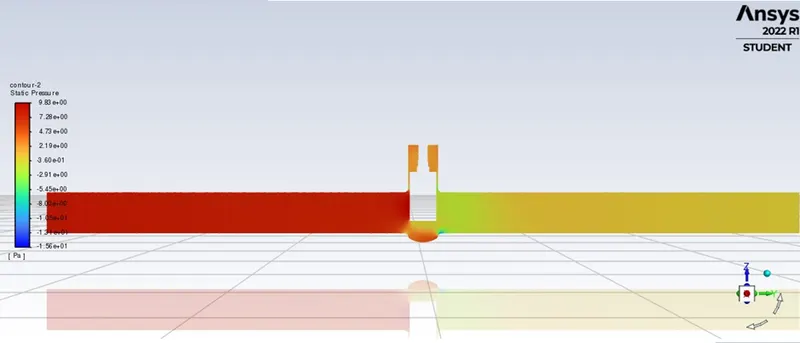 |
|
50mm |
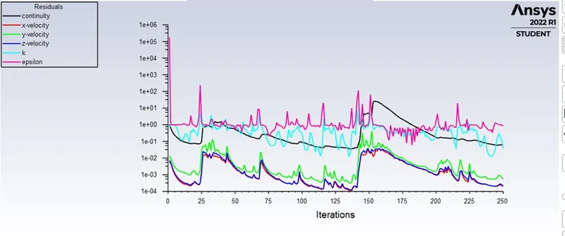 |
 |
 |
 |
|
60mm |
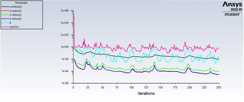 |
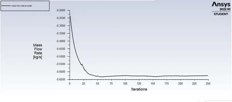 |
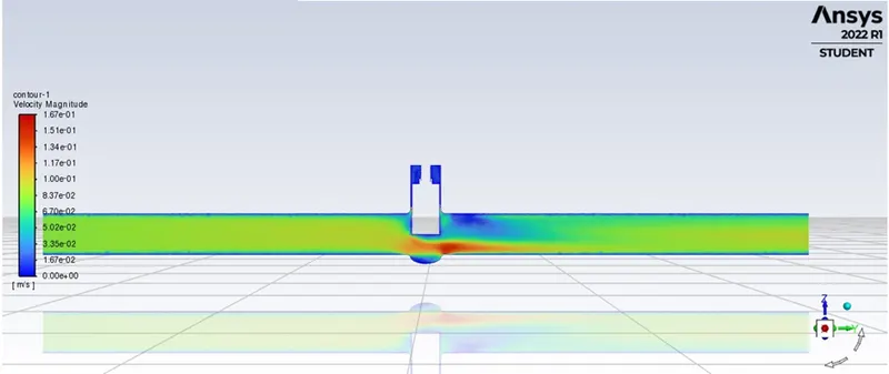 |
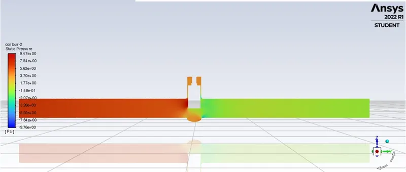 |
|
70mm |
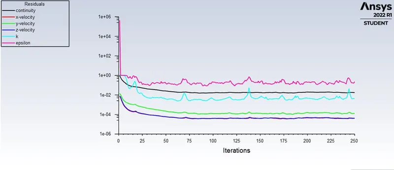 |
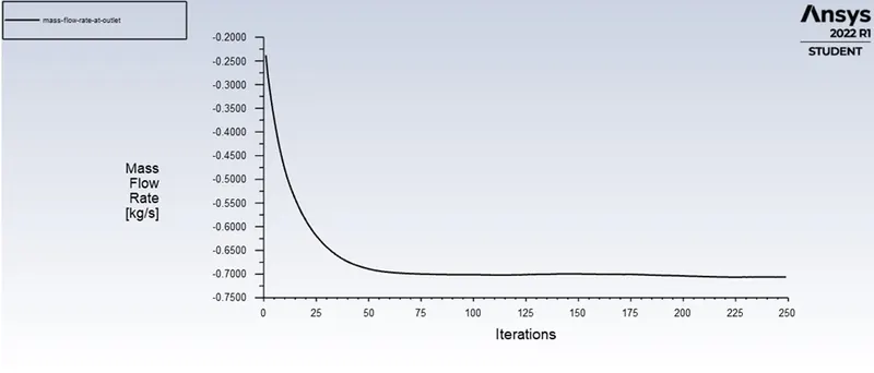 |
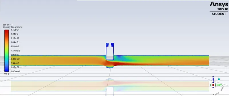 |
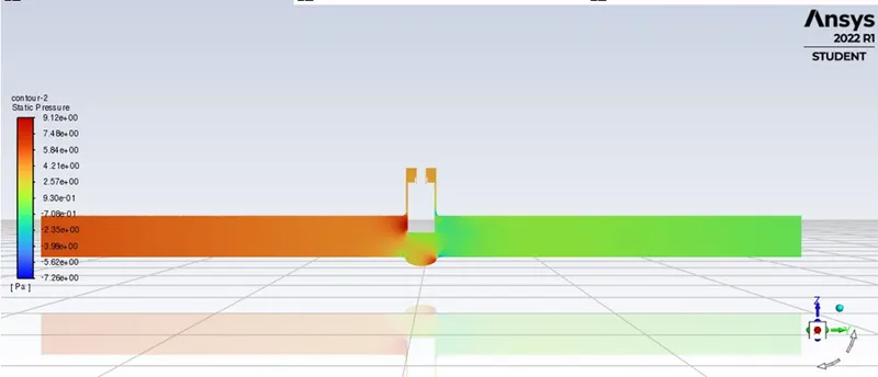 |
|
80mm |
 |
 |
 |
 |
Parametric Result:
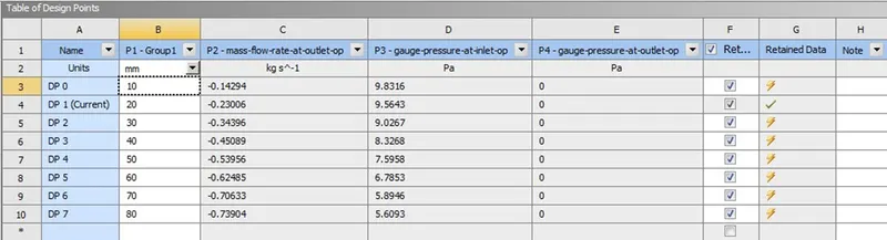
Tabular Result:
| LIFT (mm) | MASS FLOW RATE (kg/s) | GAUGE PRESSURE AT INLET (Pa) | GAUGE PRESSURE AT OUTLET (Pa) | FLOW FACTOR | FLOW COEFFICIENT |
| 10 | 0.14293552 | 9.8315629 | 0 | 51.89570136 | 44.88978167 |
| 20 | 0.23005578 | 9.5642752 | 0 | 84.68560957 | 73.25305227 |
| 30 | 0.34395913 | 9.0266648 | 0 | 130.330387 | 112.7357847 |
| 40 | 0.45088877 | 8.32675 | 0 | 177.8828818 | 153.8686928 |
| 50 | 0.53956215 | 7.5958002 | 0 | 222.8728728 | 192.7850349 |
| 60 | 0.62484795 | 6.7853396 | 0 | 273.0807304 | 236.2148318 |
| 70 | 0.70632803 | 5.8946354 | 0 | 331.1924806 | 286.4814957 |
| 80 | 0.7853997 | 4.9303778 | 0 | 402.6735766 | 348.3126438 |
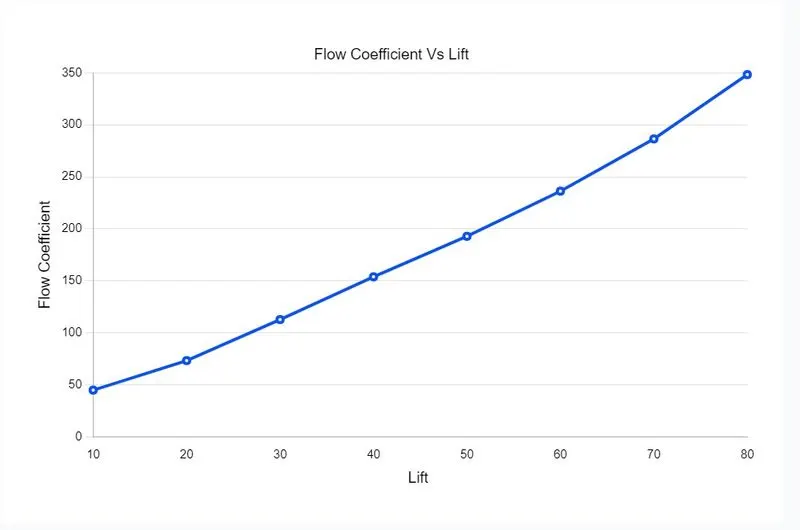
Plot for Flow Coefficient Vs Lift
CONCLUSION:
- From the observations we can conclude that there is a gradual increase in mass flow rate, flow coefficient and flow factor as the gate valve disc lift increases.
- Final gauge pressure at the outlet didn't change but with the increase in the lift of the gate disc final gauge pressure at the inlet decreased.
- As the opening or lift of the gate disc increases the velocity of flow increases.