Week 4 Challenge : CFD Meshing for BMW car
CFD Meshing for BMW car
Aim: To check and solve all geometrical errors and perform surface meshing for the given BMW car model.
Procedure:
Geometric Clean-up:
-Import the given car model in the ANSA.
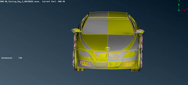
-As the car is symmetrical, we can delete one half and perform the operations on another half for simplification of the process.
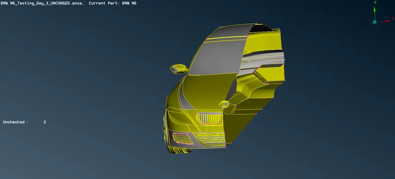
-To smoothen the perimeter of the model, click on the Length option in the Mesh deck and enter 1mm under the perimeter and macro length.
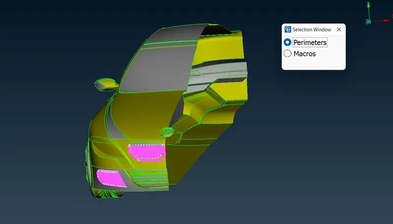
-We will perform geometrical clean-up for all the components individually.
-Following are the components present in the model
Logo
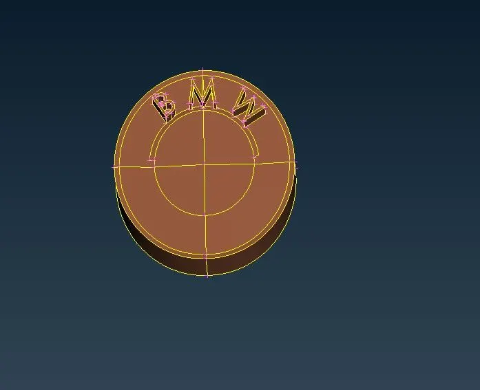
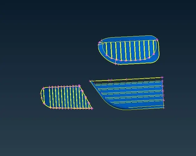
Grills
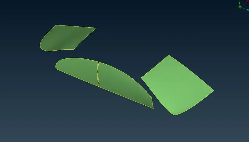
Windows and Wind Shield
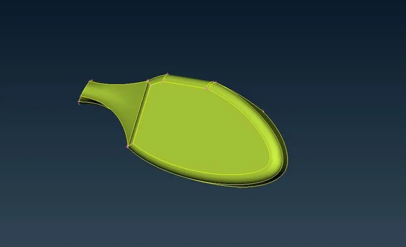
Rear View Mirror
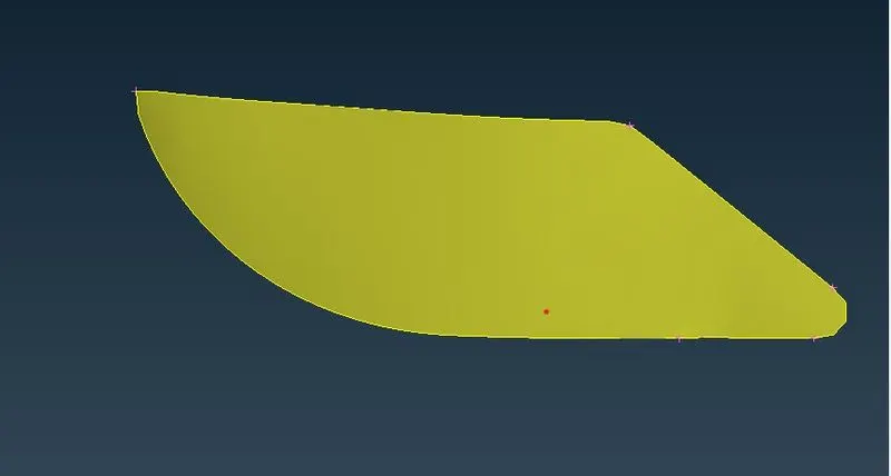
Lights
Silencer
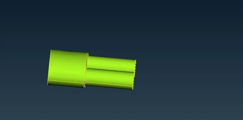
Wheels
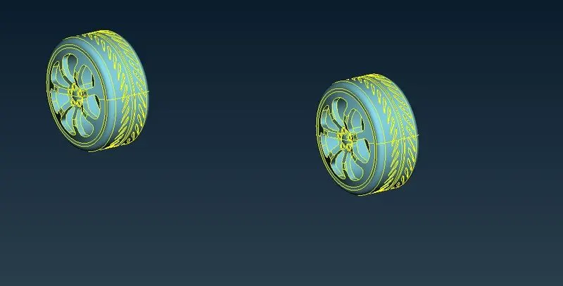
Car Body
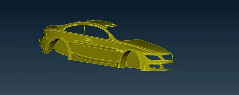
-We will perform geometrical clean-up for all the components individually. Isolate the component to be examined using the Boolean operations.
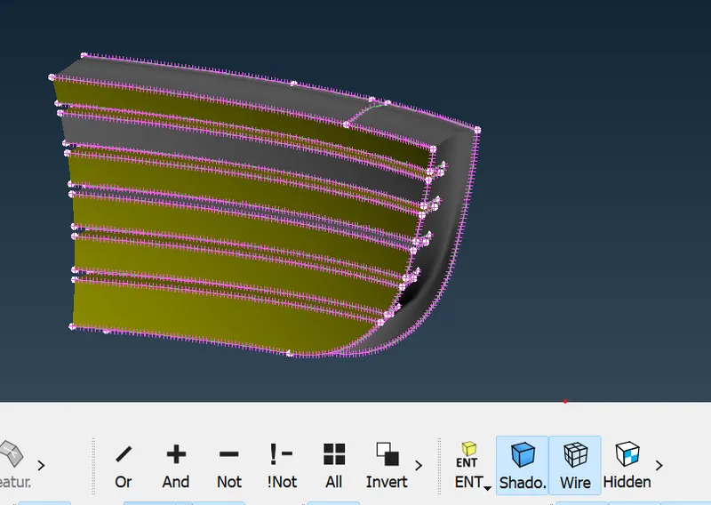
-Delete the extra surfaces in the interior of the model which has no significance. using the Delete option.
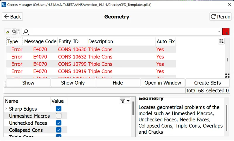
-Check for the Geometrical Error and Penetration Error for individual components and rectify them.
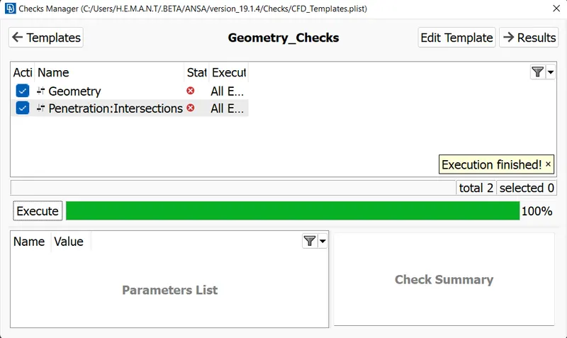
-Geometrical errors are mostly for single and triple cons. Make sure to avoid single and triple cons.
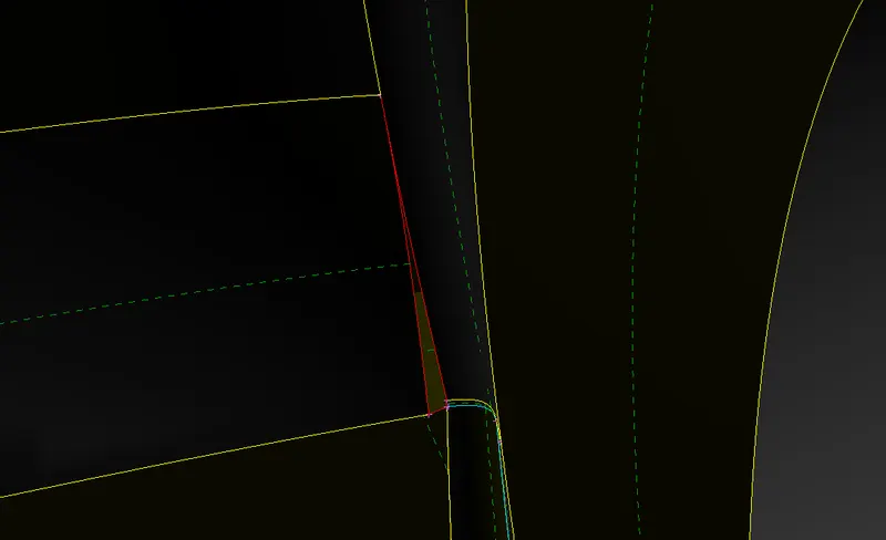
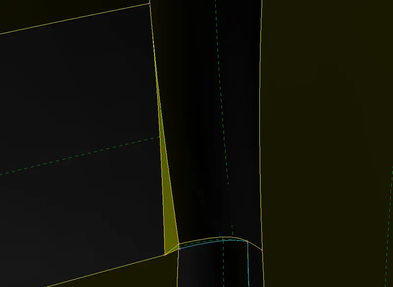
-In the case of the single cons, close the surfaces to convert them into double cons. For the below case we use the Fill Hole option.
 |
 |
- For triple cons, delete the extra surfaces using the Delete and New Face option.
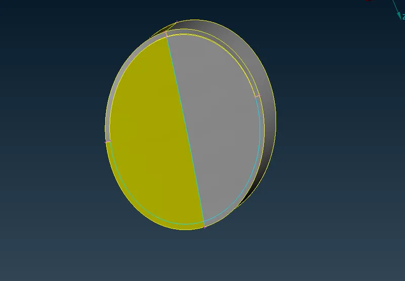 |
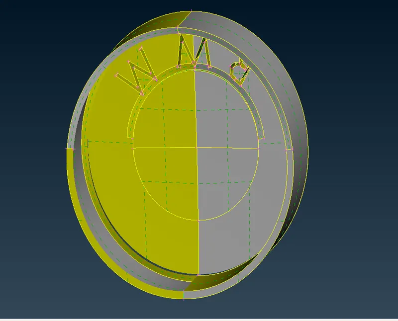 |
-Penetration Error occurs when two surfaces are not joined properly. Use the Intersect option to intersect the surfaces and delete the unnecessary surfaces.
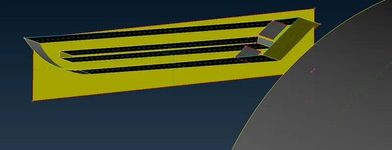
-Sometimes, the penetration error is detected but cannot be identified. In such a case, delete the surfaces using the Delete option. Make sure to retain the cons of the surfaces before deleting them using the Cons2Curve option. Then create new surfaces using those retained cons as guiding curves.
-After geometrical checks, assign PIDs for different components.
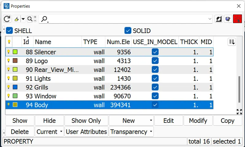
Surface Meshing:
-Target lengths for the different components of a model are as follows:
Body - 3 mm
Lights - 4 mm
Grills - 1 mm
Rims and Tyres (Wheels) - 2 mm
Optical Rear-view mirror - 2 mm
Window - 2 mm
Silencer - 3 mm
Logo - 1 mm
-Using the above target length for the different components for surface meshing using CFD meshing.
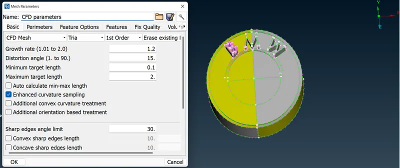
-In CFD meshing along with the target length, we need to define the minimum and maximum target length also. For minimum length, enter target length decreased by 0.5mm and for minimum, enter target increased by 0.5mm.
-Isolate the component that is to mesh. Select the Spacing option in the Perimeters module and opt for the auto-CFD option. Select the perimeters and specify the maximum and minimum lengths. Similarly, define lengths for the Macros also.
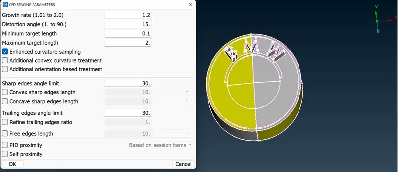
-Click on the Mesh Parameter option and specify the target length, minimum and maximum target lengths.
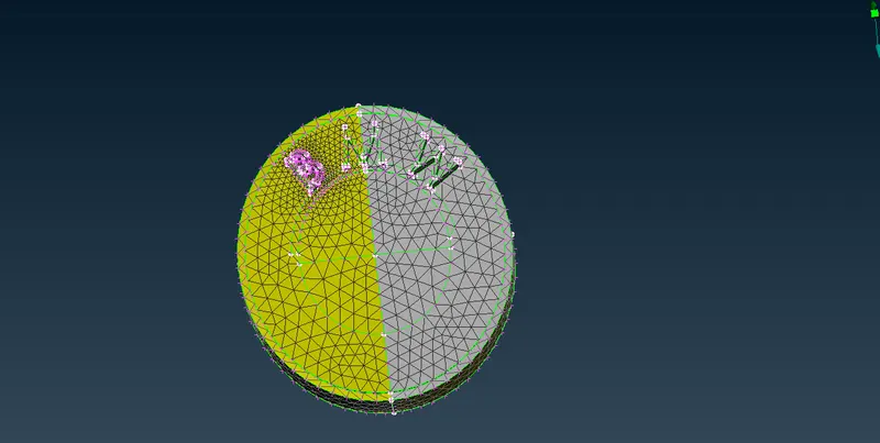
-Click on the CFD option in the Mesh Generation module and select the surface that is to mesh. Middle click to confirm the selection and proceed with the CFD Surface Meshing.
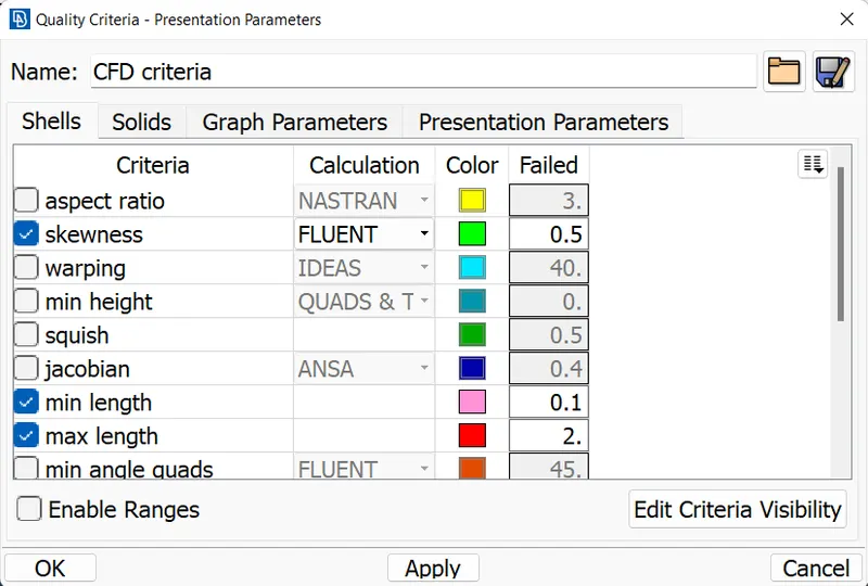
-To check the mesh quality, click on the Quality Criteria option and specify the skewness as 0.7.
For minimum length, enter the target length value decrease by 1mm and vice versa for maximum length for the quality criteria.
-Opt for the Hidden Display mode to watch the elements which deviated from the quality criteria.
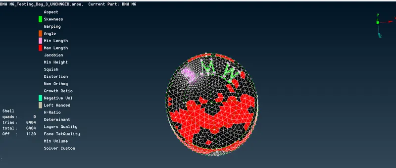
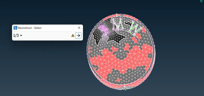
-For correcting those elements, we can use the Reconstruct option in the Shell Meshing module.
 |
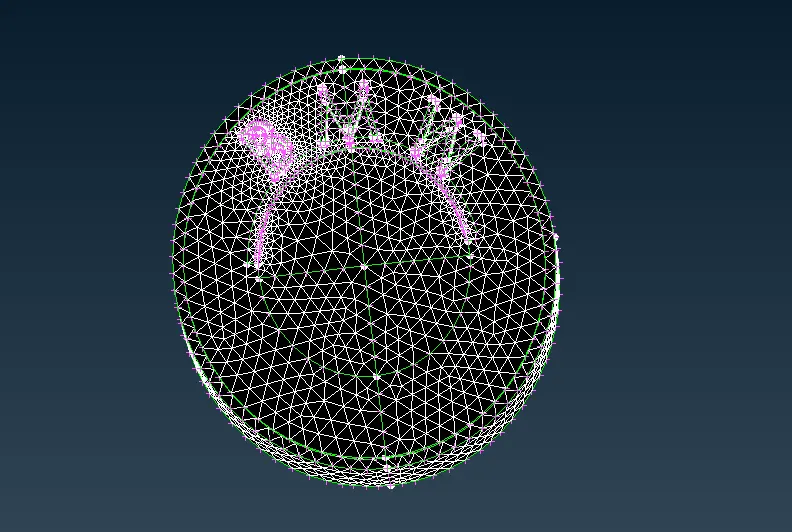 |
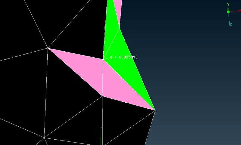
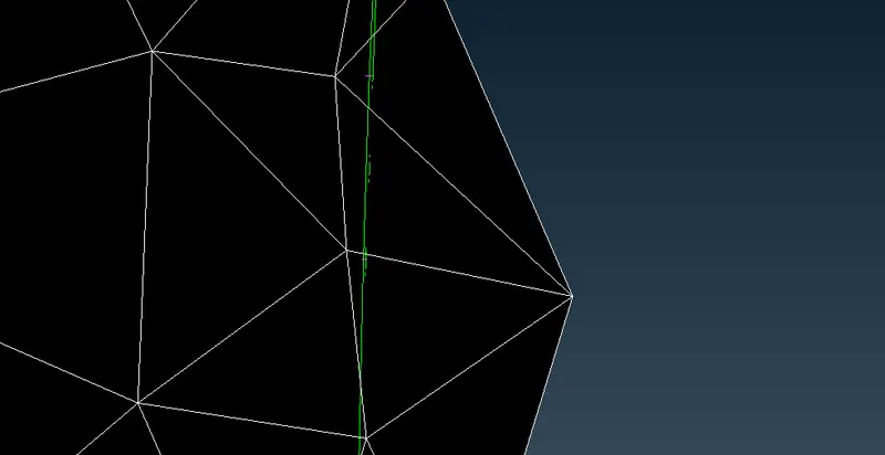
-For most of the elements, the Reconstruct option works. But for elements, it won’t work. We can use the Move option in the Grids module to move the nodes of the element. Move the node until the element attains the quality criteria.
 |
 |
-After correcting, freeze the elements using the Freeze option in the Macros module.
-Make sure to have almost zero off elements (falls under quality criteria). A few elements, in the case of the car body, cannot be corrected. In the process of correcting those elements, it will deteriorate the mesh elements of the adjacent component.
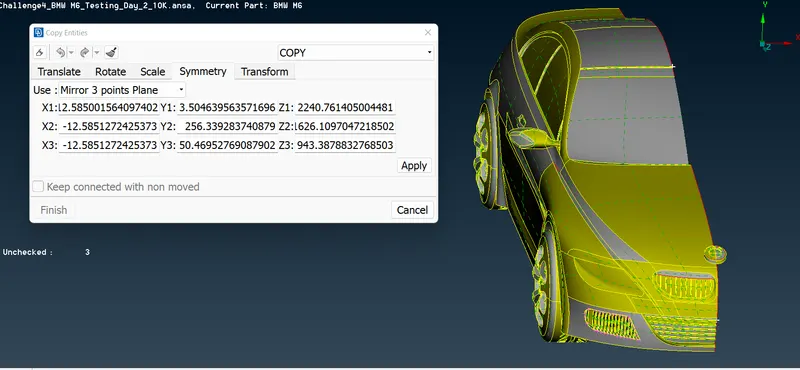
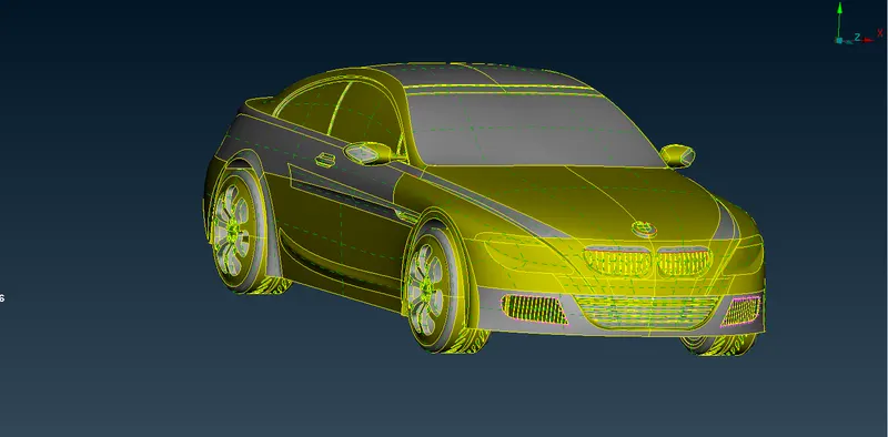
-Complete the model by creating another half of the model using the Transform tool. Click on the Copy option of the Transform tool and select the entities. Opt for symmetry with a 3-point Mirror Plane. Select the points and click on the finish to complete the process
 |
 |
Wind Tunnel:
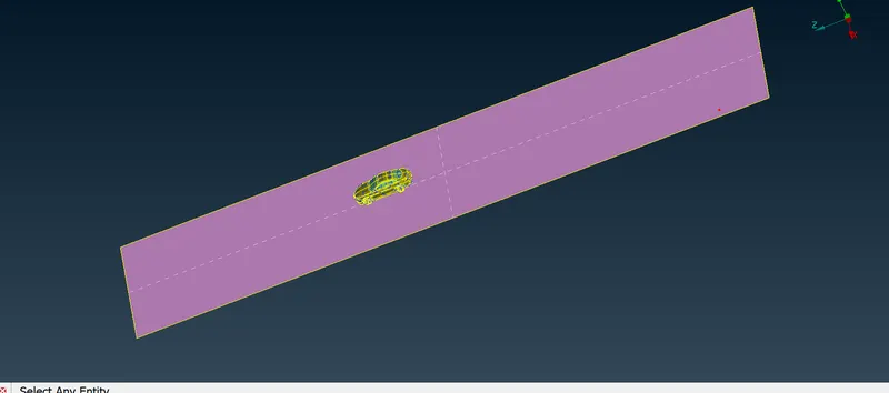
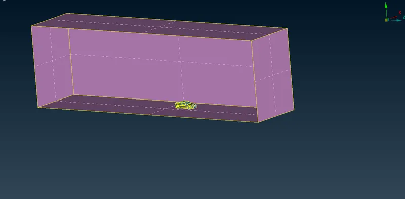
-The geometry of the enclosure/wind tunnel is as follows
|
Car Length |
x |
1308mm |
|
Inlet from Car |
4x |
5232mm |
|
Outlet from Car |
6x |
7848mm |
|
Top wall from Car |
3x |
3924mm |
|
Each Sidewall from the Car |
x |
1308mm |
|
Bottom wall from Car (Clearance) |
--- |
100mm |
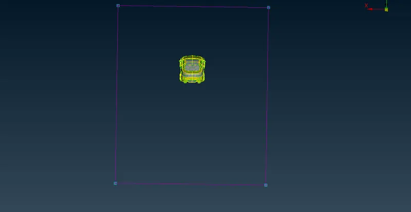
-Length of the car model is measured using the Measure tool. Based on the length of the car model perimeters of the wind tunnel are calculated.
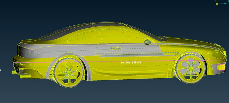
-Using the Relative option in the Points module, create the points in the space. Join those points using the Create option in the Curve module.
 |
 |
-Create a new surface as a Bottom wall using those curves. Offset the surface for the top wall using the Offset option in the Face module. Similarly, create the remaining side walls using the Face option.
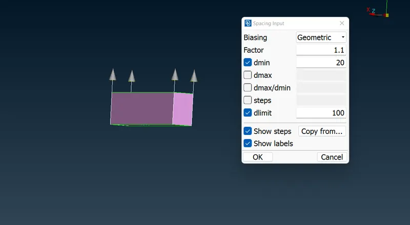
-For the surface meshing of the wind tunnel, opt for the Spacing option in the Perimeter module and specify the growth as 1.1, dmin as 20mm and dlimit as 100. Select the cons as shown below. The direction of the vector should be pointing upwards.
-Specify the mesh parameter with 100mm as the target length and, 19mm and 101 mm as maximum and minimum length.
-Click on the CFD option in the Mesh Generation module, and opt for Visible to mesh the wind tunnel surface.
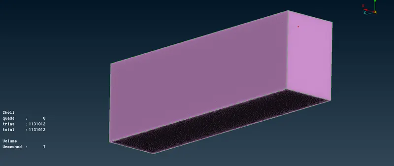
Volumetric Meshing:
-Click on the Define option in the Volumes module of the Volumetric Mesh deck. A list of 8 auto-identified volumes will be present.
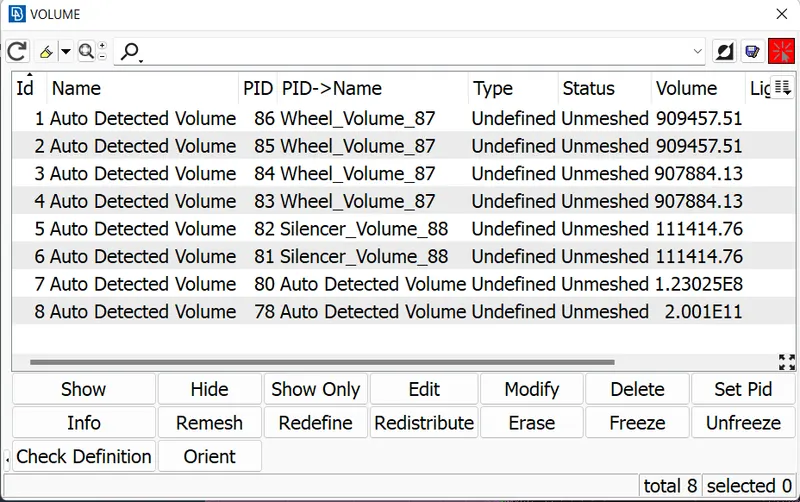
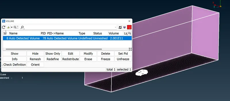
-Delete all volume except the volume of a wind tunnel.
-Click on the Tetra CFD option in the Unstructured Mesh module and choose the volume to mesh.
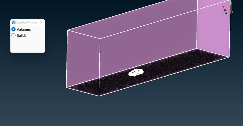
-This volumetric mesh requires very high computational power and time. It is hard to perform on a personal laptop as it may take 2 days of time.
Conclusion:
Through this challenge, I learned advanced geometric clean-up by deleting unnecessary surfaces, solving penetration and intersection problems and CFD surface meshing of the car and wind tunnel.
Model:
https://drive.google.com/file/d/1_b8DiS153v8W9T7QJiRn6uOLjliuWZ8L/view?usp=sharing