Week 8 - Simulation of a backward facing step in OpenFOAM
Simulation of Backward Facing Step Problem
Backward facing step problem is a classical example to observe and understand the separation, recirculation, and reattachment of the flow.
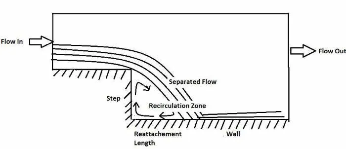
When a fully developed flow enters the domain and reaches the step, a pressure gradient exists due to an increase in cross-section, leads to flow separation. The flow detaches from the upper bottom wall and reattaches to the lower bottom wall. In between a recirculation zone is formed
Backward-facing step problem helps in analyzing practical applications in internal flow systems like diffusers, combustors, and external flows like flow around airfoil and building, etc.
Description
In the present problem, the domain consists of an inlet, backward-facing step, and an outlet. A developed steady turbulent flow enters through the inlet, passes over the step where it detaches from the boundary, and further reattaches at a particular length. The top and bottom walls are in No-slip condition.
Water enters the inlet at a velocity of 0.3781 m/s, travels through a distance of 0.08 m (inlet channel length), and passes through a step of the height of 0.01 m. The outlet channel length is 0.12 m whereas inlet channel height and outlet channel height are 0.01 m and 0.02 m respectively.
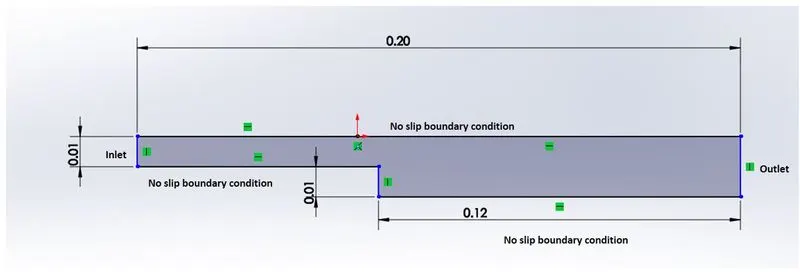
Setup
In this exercise, we are going to perform a transient simulation of an incompressible-laminar-viscous flow through the backward-facing step geometry using OpenFOAM.
Since we dealing with incompressible flows we are going to use the cavity case directory present inside the Incompressible case directory of $FOAM_TUTORIALS directory and icoFoam as a solver.
1) Initially, we open OpenFOAM by typing the following command in the bash environment.
foam
2)Open the tutorials directory where we can find many cases that demonstrate the usage of solvers present in OpenFOAM.
cd tutorials3) As we going to use icoFoam solver for incompressible-laminar-viscous flow problem, copy the cavity case directory to $FOAM_RUN directory
cp -r $FOAM_TUTORIALS/Incompressible/laplacianFoam/cavity/ $FOAM_RUN4) Open the cavity directory present in the run directory with the command
run
cd cavity
and edit the files inside the cavity directory to set up the problem.
Geometry
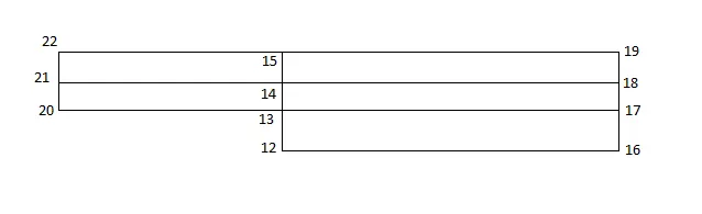
In this exercise, the entire geometry(domain) is divide into five blocks.
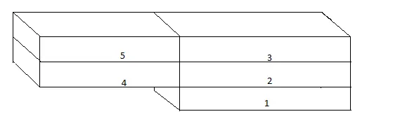
Indexing the vertices begin with the Back face of the block.
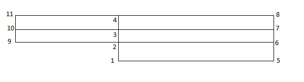
and then with Front Face of the block
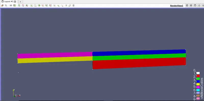
Using this information blockMesh is created using the blockMeshDict file.
cd system
gedit blockMeshDict
blockMeshDict
/*--------------------------------*- C++ -*----------------------------------*\
  =========                 |
  \\      /  F ield         | OpenFOAM: The Open Source CFD Toolbox
   \\    /   O peration     | Website:  https://openfoam.org
    \\  /    A nd           | Version:  8
     \\/     M anipulation  |
\*---------------------------------------------------------------------------*/
FoamFile
{
    version     2.0;
    format      ascii;
    class       dictionary;
    object      blockMeshDict;
}
// * * * * * * * * * * * * * * * * * * * * * * * * * * * * * * * * * * * * * //

convertToMeters 0.01;

vertices
(
  (0 0 0)         // 0


  (8 0 0)         // 1
  (8 1 0)         // 2
  (8 1.5 0)       // 3
  (8 2 0)         // 4

  (20 0 0)        // 5
  (20 1 0)        // 6
  (20 1.5 0)      // 7
  (20 2 0)        // 8

  (0 1 0)         // 9
  (0 1.5 0)       // 10
  (0 2 0)         // 11

  (8 0 0.1)       // 12
  (8 1 0.1)       // 13
  (8 1.5 0.1)     // 14
  (8 2 0.1)       // 15

  (20 0 0.1)      // 16
  (20 1 0.1)      // 17
  (20 1.5 0.1)    // 18
  (20 2 0.1)      // 19

  (0 1 0.1)       // 20
  (0 1.5 0.1)     // 21
  (0 2 0.1)       // 22


);

blocks
(
             // block 1
    hex (1 5 6 2 12 16 17 13) (100 100 1) simpleGrading (5 0.2 1)

            // block 2
    hex (2 6 7 3 13 17 18 14)(100 50 1) simpleGrading (5 5 1)

            // block 3
    hex (3 7 8 4 14 18 19 15) (100 50 1) simpleGrading (5 0.2 1)

            // block 4
    hex (9 2 3 10 20 13 14 21)(100 50 1) simpleGrading (0.5 5 1)

            // block 5
    hex (10 3 4 11 21 14 15 22)(100 50 1) simpleGrading (0.5 0.2 1)


);

edges
(
);

boundary
(
    inlet
    {
        type patch;
        faces
        (
         (9 20 21 10)
         (10 21 22 11)

        );
    }

    outlet
    {
        type patch;
        faces
        (
         (6 17 16 5)
         (7 18 17 6)
         (8 19 18 7)
        );
    }

    upperWall
    {
        type wall;
        faces
        (

        (4 11 22 15)
        (8 4 15 19)

        );
    }
    lowerWall
    {
        type wall;
        faces
        (
          (9 2 13 20)
          (2 1 12 13)
          (1 5 16 12)
          );
    }
    frontAndBack
    {
        type empty;
        faces
        (
         (1 2 6 5)
         (2 3 7 6)
         (3 4 8 7)
         (9 10 3 2)
         (10 11 4 3)

         (12 16 17 13)
         (13 17 18 14)
         (14 18 19 15)
         (20 13 14 21)
         (21 14 15 22)

        );
    }
);
mergePatchPairs
(
);


// ************************************************************************* //
Similarly time step and simulation time is added using the controlDict file.
gedit controlDictControlDict
/*--------------------------------*- C++ -*----------------------------------*\
  =========                 |
  \\      /  F ield         | OpenFOAM: The Open Source CFD Toolbox
   \\    /   O peration     | Website:  https://openfoam.org
    \\  /    A nd           | Version:  8
     \\/     M anipulation  |
\*---------------------------------------------------------------------------*/
FoamFile
{
    version     2.0;
    format      ascii;
    class       dictionary;
    location    "system";
    object      controlDict;
}
// * * * * * * * * * * * * * * * * * * * * * * * * * * * * * * * * * * * * * //

application     icoFoam;

startFrom       startTime;

startTime       0;

stopAt          endTime;

endTime          1;

deltaT          0.001;

writeControl    timeStep;

writeInterval   20;

purgeWrite      0;

writeFormat     ascii;

writePrecision  6;

writeCompression off;

timeFormat      general;

timePrecision   6;

runTimeModifiable true;


// ************************************************************************* //
We define the boundary condition in terms of pressure and velocity
Pressure
Using p file present in the 0 directory boundary condition in term of kinematic pressure (pressure/density) is defined.
cd 0
gedit p
p
/*--------------------------------*- C++ -*----------------------------------*\
  =========                 |
  \\      /  F ield         | OpenFOAM: The Open Source CFD Toolbox
   \\    /   O peration     | Website:  https://openfoam.org
    \\  /    A nd           | Version:  8
     \\/     M anipulation  |
\*---------------------------------------------------------------------------*/
FoamFile
{
    version     2.0;
    format      ascii;
    class       volScalarField;
    object      p;
}
// * * * * * * * * * * * * * * * * * * * * * * * * * * * * * * * * * * * * * //

dimensions      [0 2 -2 0 0 0 0];

internalField   uniform 0;

boundaryField
{
    inlet
    {
        type           zeroGradient;
    }

    outlet
    {
         type           fixedValue;
        value           uniform 0;

    }
     lowerWall
     {
        type               zeroGradient;
     }
     upperWall
     {
        type               zeroGradient;
     }
    frontAndBack
    {
        type               empty;
    }
}

// ************************************************************************* //
Velocity
Velocity as boundary condition is defined using U file present in 0 directory.
cd 0
gedit U
U
/*--------------------------------*- C++ -*----------------------------------*\
  =========                 |
  \\      /  F ield         | OpenFOAM: The Open Source CFD Toolbox
   \\    /   O peration     | Website:  https://openfoam.org
    \\  /    A nd           | Version:  8
     \\/     M anipulation  |
\*---------------------------------------------------------------------------*/
FoamFile
{
    version     2.0;
    format      ascii;
    class       volVectorField;
    object      U;
}
// * * * * * * * * * * * * * * * * * * * * * * * * * * * * * * * * * * * * * //

dimensions      [0 1 -1 0 0 0 0];

internalField   uniform (0 0 0);

boundaryField
{
    inlet
    {
       type            fixedValue;
        value          uniform (0.01 0 0);
    }
    outlet
    {
      type            zeroGradient;

    }
    lowerWall
    {
        type             noSlip;

    }
    upperWall
    {
        type             noSlip;

    }
    frontAndBack
    {
        type            empty;
    }
}

// ************************************************************************* //
Kinematic Viscosity
The kinematic viscosity of the fluid is change using transportProperties files present in the polyMesh directory.
cd polyMesh
gedit transportProperties
transportProperties
/*--------------------------------*- C++ -*----------------------------------*\
  =========                 |
  \\      /  F ield         | OpenFOAM: The Open Source CFD Toolbox
   \\    /   O peration     | Website:  https://openfoam.org
    \\  /    A nd           | Version:  8
     \\/     M anipulation  |
\*---------------------------------------------------------------------------*/
FoamFile
{
    version     2.0;
    format      ascii;
    class       dictionary;
    location    "constant";
    object      transportProperties;
}
// * * * * * * * * * * * * * * * * * * * * * * * * * * * * * * * * * * * * * //

nu              [0 2 -1 0 0 0 0] 1e-10;


// ************************************************************************* //
Outcomes
BlockMesh
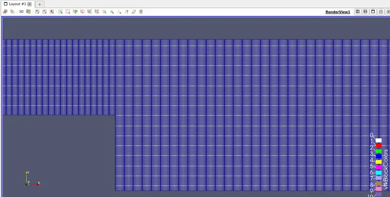
The following image is of blockMesh without grading.
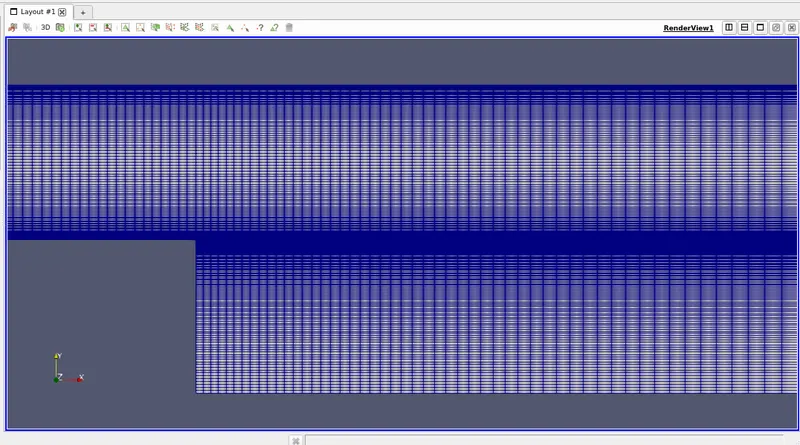
and the following image is of blockMesh with a grading of 0.2 near boundaries.
Why grade the mesh?
In this exercise, we grade the mesh near the boundary walls of the block because we are interested to observe the boundary layer phenomena near the boundary walls and separation phenomena near the step.
Plots
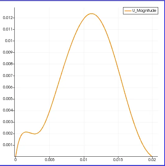
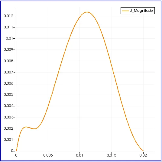
Velocity Profile at 0.085 m from inlet
Without Mesh Grading
With Mesh Grading with a grading factor of 0.2
Conclusion
We can notice that both the plots are nearly similar as we run the simulation for a very small interval of time. The significance of grading the mesh can be truly observed when we run for long intervals of time. Adding grading factor to mesh generate results nearly accurate to the real phenomenon.