Photo Realistic Rendering
1. Modeling and Photorealistic rendering of American Chopper
Objective: This course's objective is to model assembling adding decals appearance and rendering of American chopper with the help of Solidworks with Photoview 360 and Solidworks Visualize. To learn and understand the basic tools and commands of Solidworks.
- 1.Design individual components of American Chopper.
- 2.Adding Appearance after part designed.
- 3. Assembly of American Chopper from parts which we designed.
- 4.Adding decals, adding lights, camera, and scenes.
- 5. With the help of Solidworks Visualise give a photorealistic rendering of the American Chopper.
Introduction: This report contains basic part modeling adding appearance and decals and exploring the use of tools used in Solidworks.
Design methodology:
Following parts are designed and assembled in Solidworks
- Transmission Belt
- Kickstand
- Chain
- Rear Fender
- Rear Wheel
- Brake Pedal
- Front Fender
- Front Wheel
- Oil Tank
- Front Fork
- Chassis
- Engine
- Fuel Tank
Note to self: While designing any part, design constrained should use properly and make sure the sketch is fully defined then move further. Don't over define the sketch.
Basic Features which are we used while modeling our model.
Features Description:
1. Sketching Tools: Sketching is useful for creating irregular boundaries or for tracing with a digitizer. Specify the object type (line, polyline, or spline), increment, and tolerance before sketching.
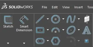
These are some basic tools we used while sketching.
Line,Circle,Spines,Rectangle,Arc,Polygon,Slot,Elipse.
- Smart Dimensions: This tool is used to give dimensions to our sketch as mentioned by the requirement.
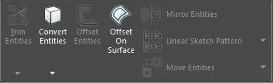
These are some more very useful sketch tools that save a lot of time while sketching.
- Convert Entities: These are used to create one or more curves in a sketch by projecting an edge, loop, face, curve, or external sketch contour.
- Offset: This tool is used to create parallel lines, concentric circles, and parallel curves. We can offset any object through a point or at a specified distance. We can create as many parallel lines and curves as with the help of the offset command.
2. Modeling Tools: These tools are used after we fully defined the sketch or completed our sketch and convert it into a 3D model with the help of these easy tools used simultaneously while modeling.
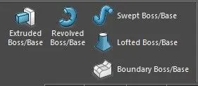
- Extrude Boss/Base: An Extruded Boss/Base feature will allow you to take a 2D sketch and add thickness to it in the third dimension (3D). This tool is used most of the time while modeling and model which is solid. In this tool, u also select where u want the extruded surface on offset or which plane.
- Revolved Boss/Base: An revolved boss/base is used to create a solid 3D model around an axis. You can revolve the sketch around an axis to add materials to it.
- Lofted Boss/Base: LOFT is one of the most basic 3D commands which is generally used for making complex and even organic shaped geometries with relative ease. The cross-sections determine the outer shape of the solid or surface. To create a 3D object using LOFT, we are required to specify at least two cross-sections.
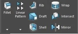
- Fillet: The fillet command is used to create rounded edges between the adjacent lines and faces in 2D and 3D. It is also used to connect two tangent arcs in 2D.
- Linear Pattern: The linear Pattern command consists of Circular pattern, Curve driven pattern, sketch driven pattern this tool help us to create more similar part or object concerning the original object and is used to create a different number of instances required to create pattern linearly.
- Circular Pattern: Circular Pattern command is used to create a different number of instances required to create patterns circularly.
- Draft: This command is used to giving draft or slope of angle provide on body or part.
- Shell: The Shell command converts a 3D solid into a hollow shell with a wall of wanted thickness.
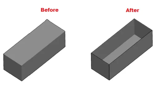
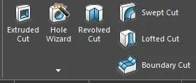
- Extruded Cut: This Command is used to removes material from the part. or select the part which will not be required in the selected contour.
- Revolved Cut: This command is used to remove the material concerning the axis. Revolved Cuts follow the same process, except they cut away material instead of adding it.
- Combine: This feature is used to combines multiple models into a single model without repositioning the models or adding bonds.
- Chamfer: This feature is used or to create slanted edges. We are required to select the two adjacent lines to create a chamfer between them and We can create the chamfer by specifying either the chamfer distance or angle.
1. Transmission Belt
A transmission Belt is used to transmit the power. The belt is a flexible element of a mechanical system. It is used to transfer the power from one System to another System.
Material Used for Belt Should be:
- It should be flexible.
- It should be reliable and durable.
- The material can withstand high tensile stress.
- More temperature can be resisted.
Feature Used to make Belt:
1. Boss Extrude
2. Fillet
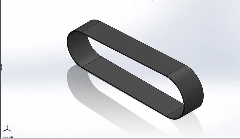
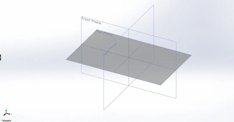
For making a transmission belt first we select the plane and then start to draw a sketch and then as per requirement we give dimensions and get a fully defined sketch and we give a 3.5mm of boss extrude and give fillet to sharp edges of Belt. The material used for the belt is Rubber so we give the appearance of matte rubber to our transmission belt.
2. KickStand:
A kickstand or Side stand is used to support our American Chopper. in most of the motorcycles that kept the bike upright without leaning against another object or the aid of a person. It helps to support the bike for parking or for standing by making contact with the ground to give stability.
Feature Used to make Kickstand:
1. Loft
2. Dome
3. Cut extrude
4. Boss extrude
5. Fillet
6. Split tool
Split Tool is used to performs the division of features into two or more using a line string drawn by the user as the splitting line. we can also able to split faces on multiple bodies with a single command.
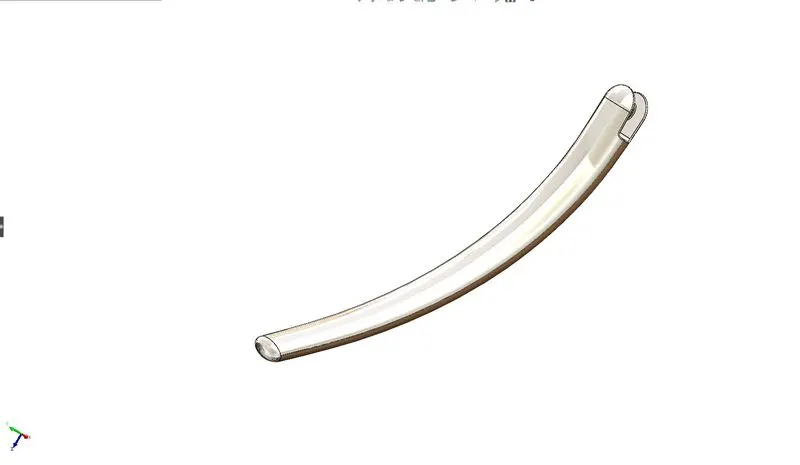
for making a kickstand we selected the right plane and make two ellipses one on the top side and one on the bottom side and a path is created for the loft with the help of this path which was created to connect the ellipses to create a body of our kickstand. Then we use the Dome feature on both sides. With the help of extruded cut, the slot is created with the help of a sketch to connect our stand with the chassis. The split command is used at the bottom where stand contact with the ground. Filets are provided to sharp edges. and give chrome plate appearance to our chopper kickstand.
3. Chain
The working of the chain drive is very simple. If you have seen how bicycles work on the chain, you pedal on the front and the chain rotates the rear via the chain. There are two sprockets, one on the front and the other on the rear with the chain connecting them. When the front is rotated, the chain moves along with it and this makes even the rear move since it is also connected to the chain. This is how the power is transmitted to the wheels via a chain. Now like bicycles, the same applies to motorcycles, just the front is connected to the engine and the gears and this transmits power to the rear via the chain.
Feature Used to make Chain:
1. Extrude Boss/Base
2. Curve Driven Pattern in (Liner Pattern)
3. Circular pattern
4. Fillet
5. Mirror
6. Combine
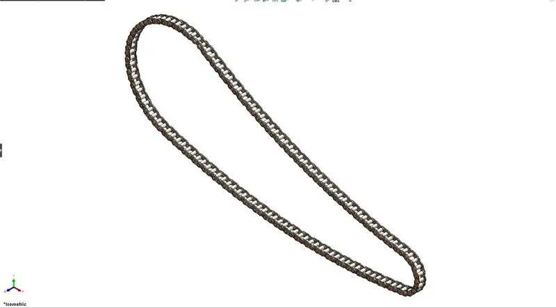
For making the drive chain of our chopper we created the profile for our chain with the help of 3 point arcs and tangent relation between them to create the path for chain drive. Then we created two different chain Plates which we are used to joint our chain with the help of connecting pins. For proper arrangement with the tangent profile of our chain we then select curve driven pattern to mirror and make a linear pattern for our chain. All the components of the chain are combined as a single part.
4. Rear Fender
Fenders (or “mudguards” ) are what will keep you from having a skunk stripe on your backside if you ride in the rain, and a front fender will help protect your feet and ankles from spray if you're riding in the rain or even through a puddle. The fender is also used as a rear-wheel cover. The fenders which we designed look like our chopper.
Feature Used to make Rear Fender:
1. Revolve Boss/Base
2. Split
3. Fillet
4. Shell
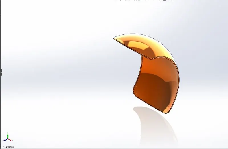
For making a fender we sketch the fender in the front plane using a three-point arc and offset tool to give thickness value for our fender. Then we created the axis of revolution and we give direction to revolved feature and select the contour for our revolved boss base feature. As per dimensions we create sketches on the fender with the help of the Intersection Curve in the Convert Entities tool and use this for making a curve design for our fender. Then we use the split feature and shell feature to complete our design.
5. Rear Wheel
A wheel is a circular object that, together with an axle, rolls easily. They are used to give motion to our chopper and help to move forward as well as give some amount of cushioning effect. The wheel can mean lots of other circular parts like Rim, Tyre, Rotor, caliper.
Feature Used to make Rear Wheel:
1.Revolve Boss/Base
2. Extruded Boss/Base
3. Extruded Cut
4. Revolved Cut
5. Circular Pattern
6. Chamfer
7. Fillet
9. Combine
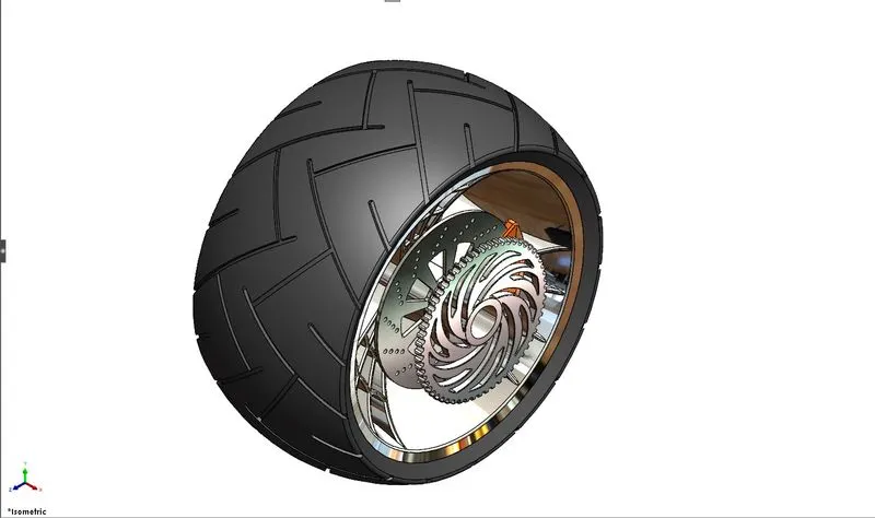
For making the rear wheel first we make a rim profile sketch on revolve about an imaginary axis on the front plane. Then we make a spider web design on Rim for the look and use the extruded boss base feature. For making this spider web design more attractive we use convert entities and use curve structure to give more look to the rim. And then use a circular pattern to make a copy of the rim required number. And use combine Then we make rotor with help of sketch and extruded boss base then we create some holes on the rotor to heat dissipation and use cut extruded feature and then use the linear pattern to copy that pattern all over the rotor. Then we again make a rear sprocket for a chain with help of extruded boss base and cut extrude for making a pattern on the sprocket. In the last, we convert entities of the rim and then use this sketch and use revolved boss/base feature to make a tire. and then use a sketch tool and draw a pattern for our tire to tire get a grip on the road while in motion.
6. Pedal
Pedal where rider of our chopper can place his foot on it or rest on it to handle the rear brake as well as gear.
Feature Used to make Pedal:
1. Extruded Boss/Base
2. Fillet
3. Revolve Boss/Base
4.Dome
5.Liner Pattern
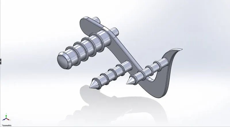
For making this Pedal or Foot support for our rider we sketched as per designed and then use the extruded boss base feature. For making or connect this pedal to intersect or attach with the chassis we draw some sketches and use the extruded boss base feature. Then for the footrest, we draw the cylinders on the side profile and make a ring-like design on that cylinders and use the linear pattern to make a copy of this ring-like structure.
7. Front Fender
Fender is designed to protecting the rider or other persons from sand, rock, or any other substances on road don't get revert back or damage anyone rider or surroundings persons or vehicle fender is also designed to protect our foot from mud and water, etc.
Feature Used to make Front Fender:
1. Revolve Boss/Base
2. Split
3. Fillet
4. Shell
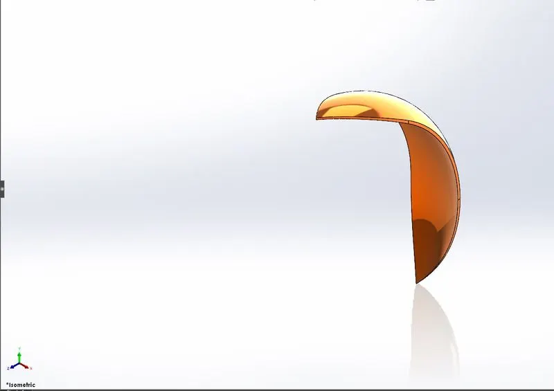
For making a fender we sketch the fender in the front plane using a three-point arc and offset tool to give thickness value for our fender. Then we created the axis of revolution and we give direction to revolved feature and select the contour for our revolved boss base feature. As per dimensions we create sketches on the fender with the help of the Intersection Curve in the Convert Entities tool and use this for making a curve design for our fender. Then we use the split feature and shell feature to complete our design.
8. Front Wheel
A wheel is a circular object that, together with an axle, rolls easily. They are used to give motion to our chopper and help to move forward as well as give some amount of cushioning effect. The wheel can mean lots of other circular parts like Rim, Tyre, Rotor, caliper.
Feature Used to make Front Wheel:
1.Revolve Boss/Base
2. Extruded Boss/Base
3. Extruded Cut
4. Revolved Cut
5. Circular Pattern
6. Chamfer
7. Fillet
9. Combine
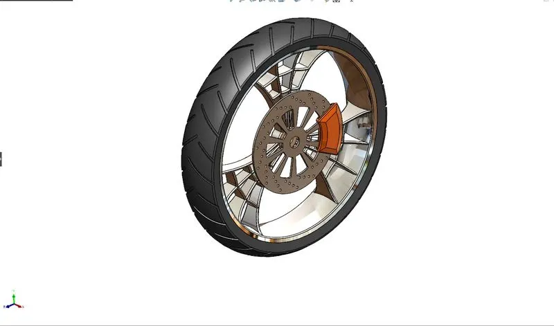
This wheel is front-wheel the size of this wheel is small as compared to rear-wheel dimensions are changed but the procedure for making the front wheel is the same. For making the Front-wheel first we make a rim profile sketch on revolve about an imaginary axis on the front plane. Then we make a spider web design on Rim for the look and use the extruded boss base feature. For making this spider web design more attractive we use convert entities and use curve structure to give more look to the rim. And then use a circular pattern to make a copy of the rim required number. And use combine Then we make rotor with help of sketch and extruded boss base then we create some holes on the rotor to heat dissipation and use cut extruded feature and then use the linear pattern to copy that pattern all over the rotor. Then we again make a rear sprocket for a chain with help of extruded boss base and cut extrude for making a pattern on the sprocket. In the last, we convert entities of the rim and then use this sketch and use revolved boss/base feature to make a tire. and then use a sketch tool and draw a pattern for our tire to tire get a grip on the road while in motion.
9. Oil Tank
Oil Storage for our chopper is used to motorcycle works properly smoothly and lubricate or supply the oil to the engine or other parts for lubrication.
Feature Used to make Oil Tank:
1. Extrude Boss/Base
2. Fillet
3. Shell
4. Combine
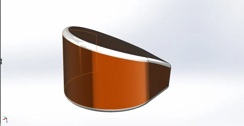
For making an Oil Tank for our chopper we select the proper plane then start to sketch by using 3 point arc and lines and make them tangent with arc and extrude it as per requirement. Then create another sketch and extrude it and to obtain that slope structure uses the split command and achieve the design of the Oil Tank. For making hollow oil tanks and specific thicknesses use the shell command.
10. Front Fork
A bicycle fork is the part of a bicycle that holds the front wheel. The “fork” is the suspension at the front of a motorcycle. It's called a fork because it has two prongs that go around each side of the wheel. It is a handle for our chopper and also consists of bike equipment like buttons and brake and clutch mount on the fork of our bike.
Feature Used to make Oil Tank:
1. Extrude Boss/Base
2. Revolved Boss/Base
3. Fillet
4. Extruded Cut
5. Dome
6. Revolved Cut
7. Swept Boss
8. Project Curve
9. Mirror
10. Combine
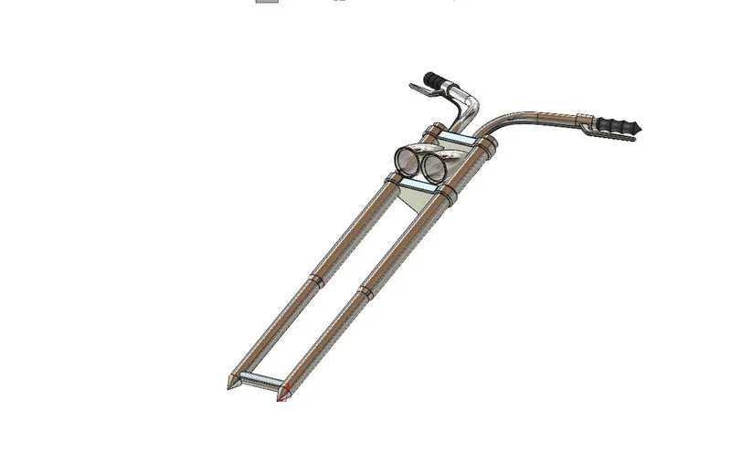
For making this fork we make one side of the fork then mirror another side because it's the same as this side create a sketch on the front plane then revolve it. Then create the half side of the triple clamp of the fork make a sketch and then use extrude boss/base. Then create a headlight using revolve boss base. Then sketch brake and use extrude boss base. And after that use profile path and sketch to make a cable. After that create a mirror using a plane. and combine all the bodies. Give appearance to Handle grip rubber and chromium plate for a fork.
11.Chassis
Chassis is the main support structure of the vehicle which is also known as 'Frame'. It bears all the stresses on the vehicle in both static and dynamic conditions. It is a skeleton on which all components of the bike are assembled or attached and fix on the chassis.
Feature Used to make Chassis:
1. Swept Boss
2. Project Curve
3. Mirror
4. Revolved Boss/Base
5. Linear Pattern
6. Fillet
7. Extruded Cut
8. Dome
9. Revolved Cut
10. Swept Boss
11. Project Curve
12. Mirror
13. Combine
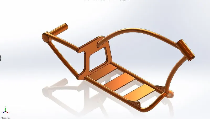
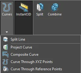
Project Curve: Project curve, well it is a tool you are going to use to form 3D curves from two 2D curves from two different planes. we need to do is basically select the two curves we drew and it will form a 3D Curve based on the curves we selected.
For making the Chassis or skeleton of our chopper model we need to insert a sketch image of our chopper model and then start our sketching and try to match the sketch profile using the spline curves tool which is very handy and make a tangent arc and add dimensions to sketches and make tangent relation and make fully define sketch. By using the very projected curve tool project curve and by using plane create a path for tube-like the structure of our bike. And after that all curves and chassis structures make a supports plate for our engine using extruded boss base. and at last, use combine tool to select all structures and combine chassis body.
12. Engine
An engine or motor is a machine designed to convert one form of energy into mechanical energy. Heat engines convert heat into work via various thermodynamic processes. An engine, or motor, is a machine used to change energy into a movement that can be used. The energy can be in any form. Common forms of energy used in engines are electricity, chemical (such as petrol or diesel), or heat. When a chemical is used to produce energy it is known as fuel.
Feature Used to make Chassis:
1. Extruded Boss/Base
2. Revolved Boss/Base
3. Extruded Cut
4. Revolved Cut
5. Circular Pattern
6. Project Curve
7. Swept Boss/Base
8. Dome
9. Combine
10. Mirror
11. Chamfer
12. Fillet
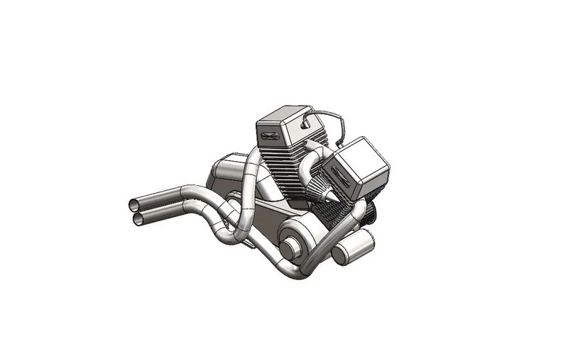
For making our Chopper twin type engine first we insert a sketch picture of our chopper then we create a sketch image and then one by one use Extruded Boss command and make an engine model with the help of boss base and midplane. after that we start to create two one big and small circles for our chain pulleys as per shown using an extruded boss base, then use extruded cut feature for cuts on pulley like an actual pulley for grip for our rubber. Then on another side of the engine, we make a small sprocket for our chain drive using the extruded boss base and extruded cut feature for cuts on sprockets. Then we start to make exhaust pipes for our engine for that we have to make 2d curves using tangency and 3 point arc then use the projected curve tool for making 3d curve for the exhaust pipe and create the swept boss base. Then we mirror our engine on a plane using the mirror command. And at the end, we make spark plugs for our engine. and we make an air filter for our chopper model using revolve boss base. Then use the combine tool and combine all the components of our engine.
Surface Features Description:
- Surface Tools: Surfacing tools are similar to solid tools but this tool creates surfaces instead of solid bodies. Surface tools like (Lofted surface, Swept surface, Surface trim, Boundary surface, Extruded Surface)
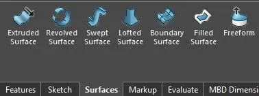
- Extruded Surface: This tool is used for extruding or extend the surface which was already created. we can extend the same surface with this tool or extend the surface which is tangent.
- Lofted Surface: Loft Surfaces are surfaces generated by multiple 3D Curves or existing edges creating a smooth tangency between the selected curves. Match Points are created between each selection denoting the orientation and path of the loft surface.
- Boundary Surface: Surface boundaries are defined from closed polygons, such as a closed polyline or a parcel, or surfaces.
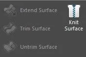
- Knit Surface: Surface knitting is a process of recognizing where two parts have surfaced in contact, and then splitting the surfaces if necessary to get identical surfaces.
13. Gas Tank
A fuel tank (also called a petrol tank or gas tank) is a safe container for flammable fluids. Though any storage tank for fuel may be so-called, the term is typically applied to part of an engine system in which the fuel is stored and propelled (fuel pump) or released (pressurized gas) into an engine. This tank is to store the fuel for our chopper.
Feature Used to make Chassis:
1. Swept Surface
2. Loft Surface
3. Boundary Surface
4. Project Curve
5. Knit Surface
6. Swept Cut
7. Combine
8. Shell
9. Mirror
10. Fillet
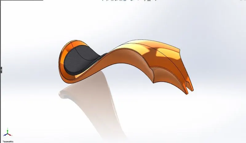
For making a gas tank we use surface features to create a gas tank of our chopper we use the front plane for making our tank using splines and make tangent relations. Then use project curve to make curve profile for our gas tank and use extrude surface. Then create a slot for gas tank fitted with chassis using the sketch and swept cut feature and boundary surface. Then create a sketch for the seat and use surface extrude. after that use the knit surface command to get the identical surface. and at last use a fillet command on sharp edges of our tank.
- Using all these features we completed part modeling for our American Chopper. Before start our assembly of the chopper we add some decals on our Rear Fender, Gas tank, Oil Tank to give a more cool look for our chopper and try to make a realistic design. After adding decals we start Assembling parts of our American Chopper.
Assembly of American Chopper:
- After adding decals we choose the assembly section for mating of our chopper parts like engine, fender, wheel, pedal, chain, Transmission Belt, etc.
- For mating and assembly on chopper components, we use mating-type like Concentric, Coincident, Parallel, etc.
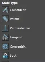
- Mating Types:
- Coincident: A coincident constraint causes two points to coincide, or a point to lie anywhere on an object or the extension of an object.
- Parallel: In geometry, parallel lines are lines in a plane that do not meet; that is, two straight lines in a plane that do not intersect at any point are said to be parallel.
- Concentric: Circle those having a common center or the same point.
- Advance Mate: This type of mate is an advanced mate in which we have to select the two faces and the selection of width.
- After selecting the Assembly section we first insert components of our chopper one by one step by step we use all these mate type constraints for our chopper parts. First, we insert our Engine and simply click ok then Solidworks will automatically fix our chassis. We can change to float if we want to unfix our chassis or object.
- Then we insert our Engine and use the mating-type we want for more advanced and accurate mating we choose planes of our parts for proper and defined assembly if our mating parts is not fully constrained we can see (-) this sign in our feature manager shows our parts is not fully constraint with that body or part.
- Like that we insert all the parts one by one and complete our American Chopper assembly successfully.
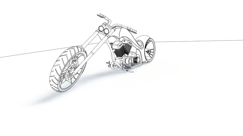
This is a contour or wireframe image of our assembled American Chopper in Solidworks.
- After assembly, we need to get a photorealistic appearance to our chopper model using Photoview 360 and Solidworks Visualize.
- Rendering: Rendering or image synthesis is the process of generating a photorealistic or non-photorealistic image from a 2D or 3D model utilizing a computer program. The resulting image is referred to as the render.
- PhotoView 360: PhotoView 360 is a visualization and rendering solution included with SOLIDWORKS Professional and SOLIDWORKS Premium. Providing a highly interactive environment for viewing designs as well as for creating photo-realistic renderings that can be used to showcase your designs.
- Solidworks Visualize: SOLIDWORKS® Visualize allows you to leverage your 3D CAD data to create photo-quality content in the fastest and easiest way you can–from images to animations, interactive web content, and immersive Virtual Reality.
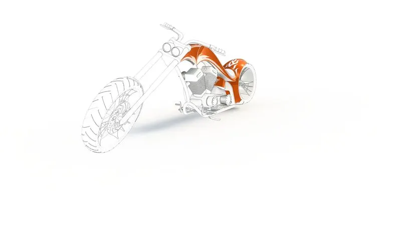
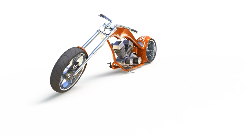
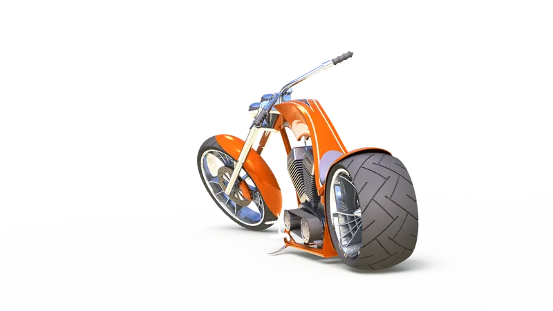
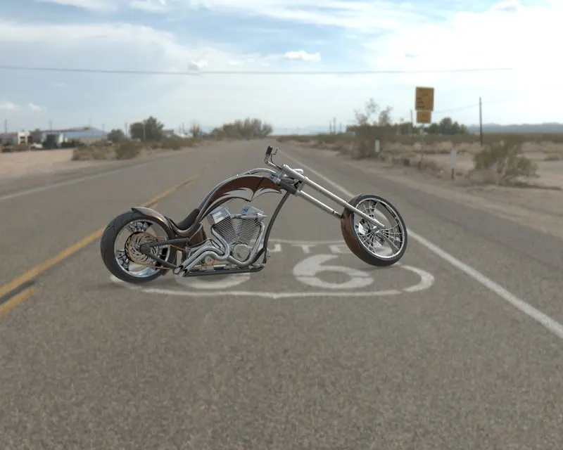
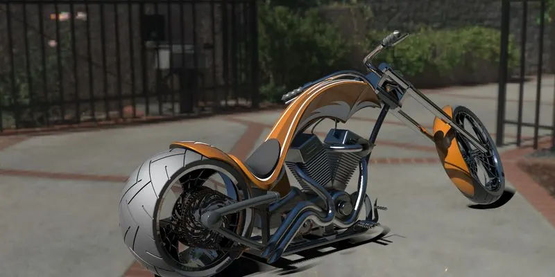
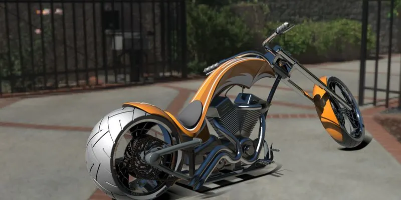
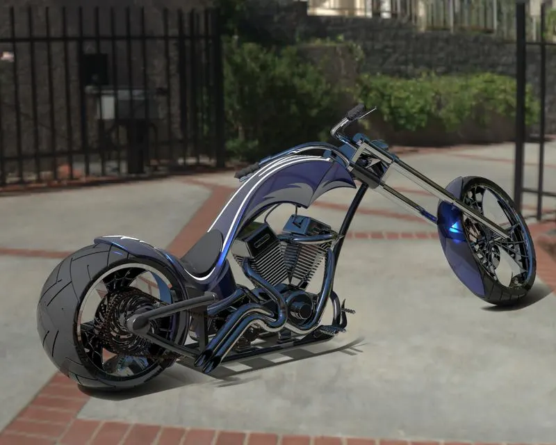
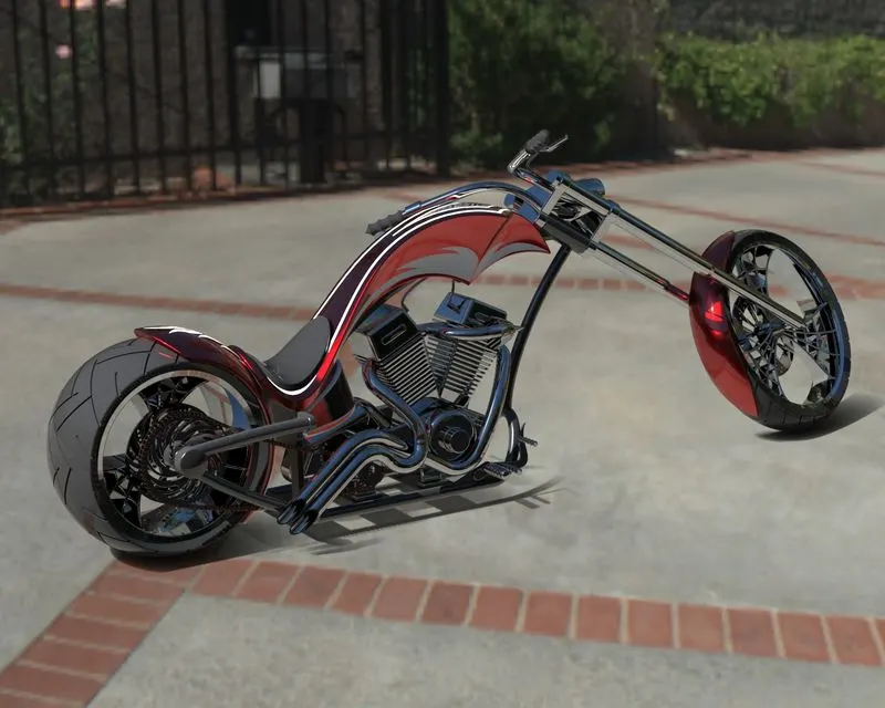
Conclusion: We can model any complex design in Solidworks and if we want to make any changes we can do Solid works. In this project of the model of American chopper, we learn some new tools use decals rendering use photo view 360 more simple tools which are very simple to use.