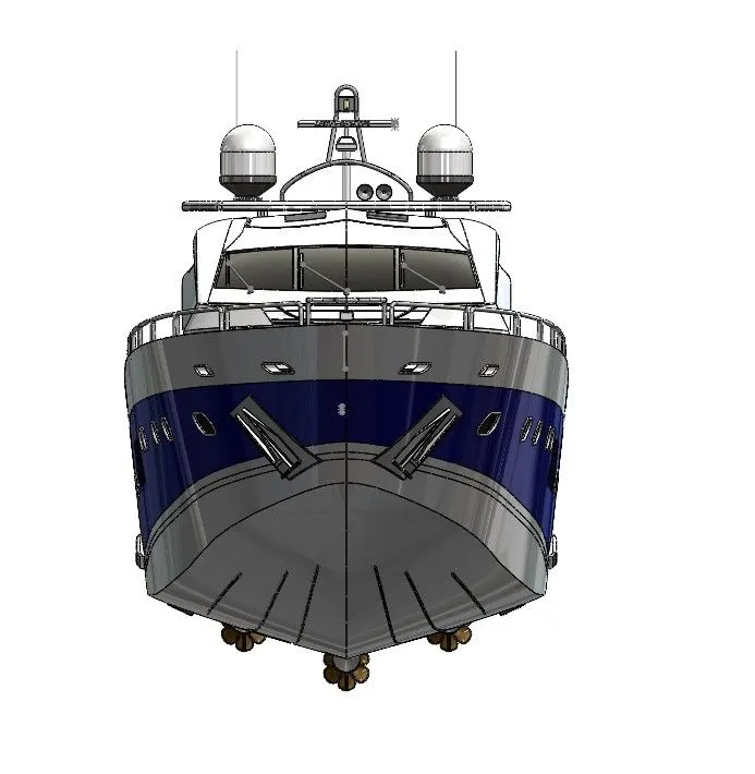
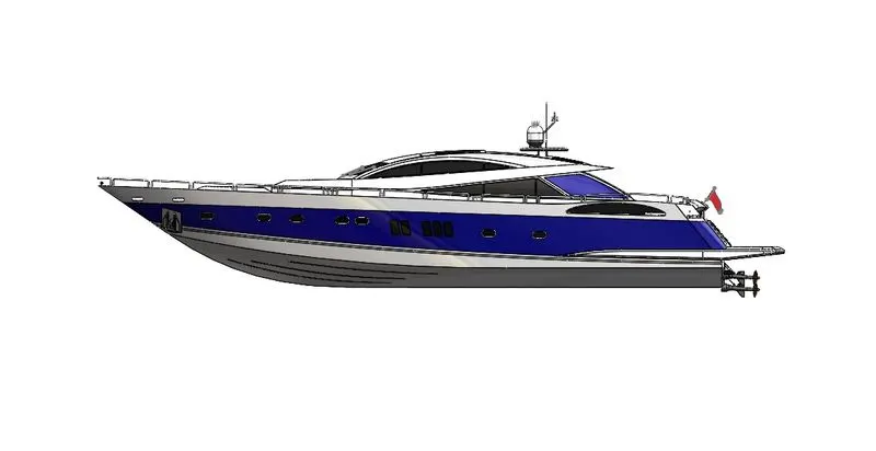
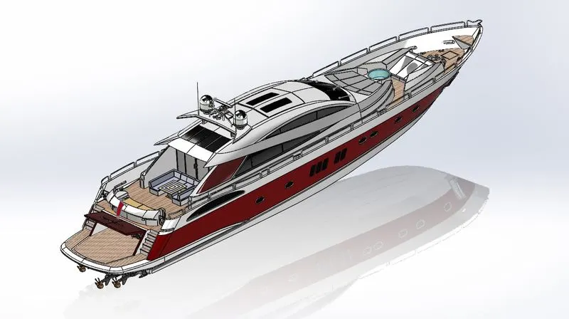
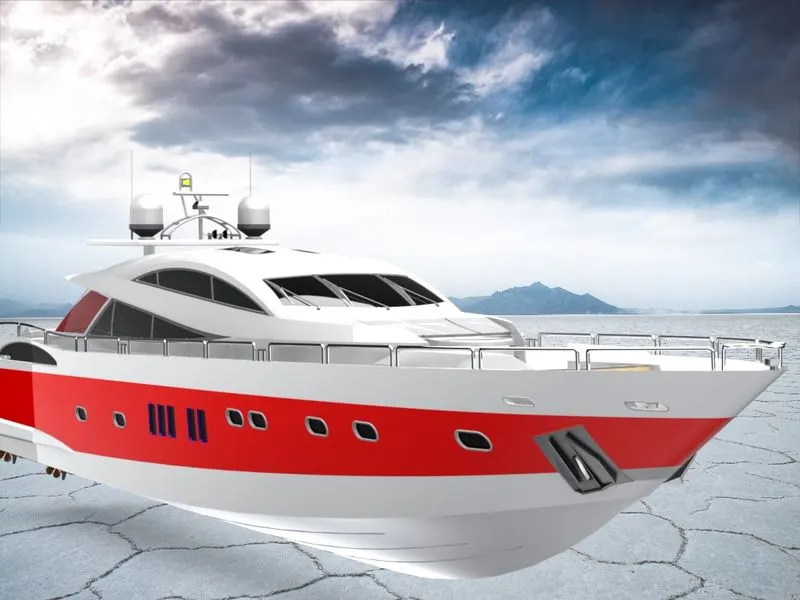
Radar Mast & Final Assembly of Yacht
1. Modeling and Final Assembly of Yacht and Radar Mast
- Objective:
- In this Yacht Modeling basically, we learn basic tools use for surface modeling for complex design or structure.
- We also use basic features for our Yacht to model and then assemble the yacht.
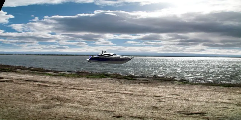
- Then we use Photoview 360 for Photorealistic Rendering for yachts.
- Introduction:
Solidworks is the CAD Software we use for this entire modeling assembling and rendering of the yacht.
- Yacht: A yacht is a sailing or power vessel used for pleasure, cruising, or racing. There is no standard definition, so the term applies to such vessels that have a cabin with amenities that accommodate overnight use. To be termed a yacht, as opposed to a boat, such a pleasure vessel is likely to be at least 33 feet (10 m) in length and may have been judged to have good aesthetic qualities. The YAcht is a vessel used for private cruising, racing, or other noncommercial purposes.
- Design Methodology for Yacht:
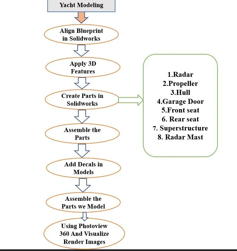
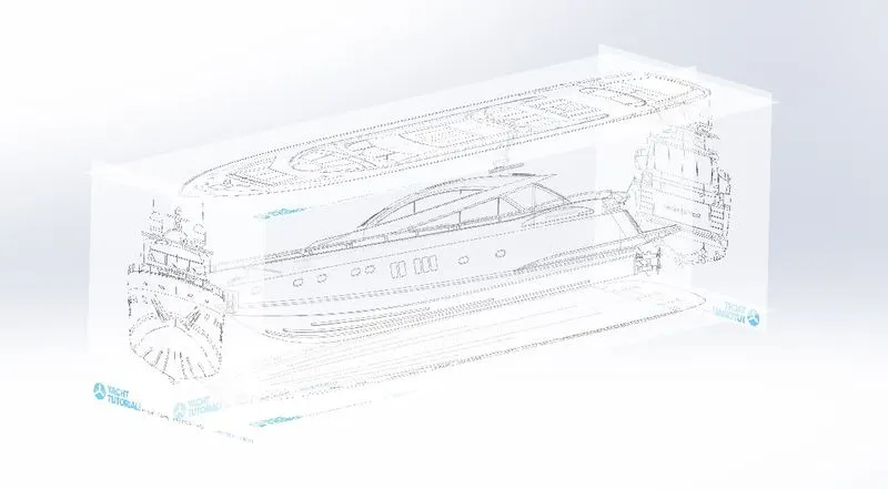
- Description: Before Creating and start part Modeling we set up our Blueprints of Yacht with proper alignment and Dimensions.
Features Description:
- Sketching Tools: Sketching is useful for creating irregular boundaries or for tracing with a digitizer. Specify the object type (line, polyline, or spline), increment, and tolerance before sketching.
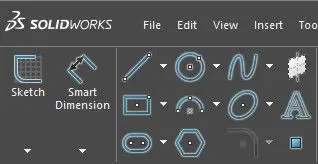
These are some basic tools we used while sketching.
Line,Circle,Spines,Rectangle,Arc,Polygon,Slot,Elipse.
- Modeling Tools: These tools are used after we fully defined the sketch or completed our sketch and convert it into a 3D model with the help of these easy tools used simultaneously while modeling.
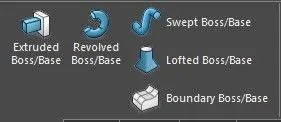
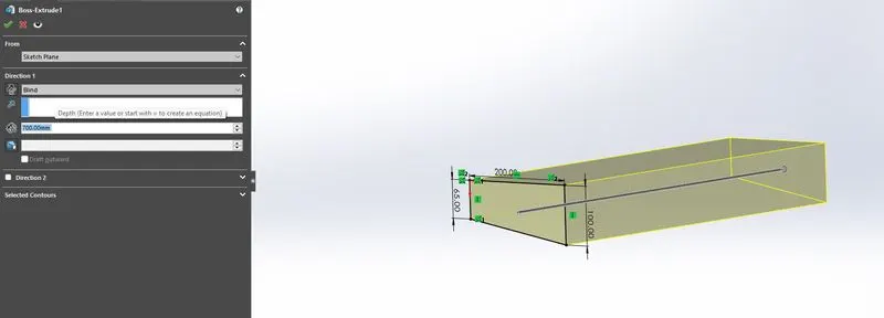
- Extrude Boss/Base: An Extruded Boss/Base feature will allow you to take a 2D sketch and add thickness to it in the third dimension (3D). This tool is used most of the time while modeling and model which is solid. In this tool, u also select where u want the extruded surface on offset or which plane.
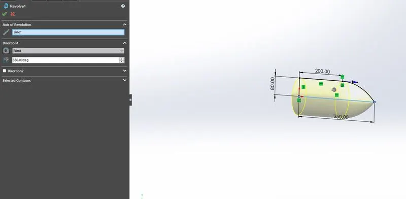
- Revolved Boss/Base: An revolved boss/base is used to create a solid 3D model around an axis. You can revolve the sketch around an axis to add materials to it.
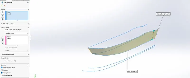
- Lofted Boss/Base: LOFT is one of the most basic 3D commands which is generally used for making complex and even organic shaped geometries with relative ease. The cross-sections determine the outer shape of the solid or surface. To create a 3D object using LOFT, we are required to specify at least two cross-sections. We use guide curves for the more perfect creation of our surfaces.
Modeling Tools:
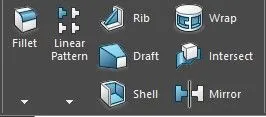
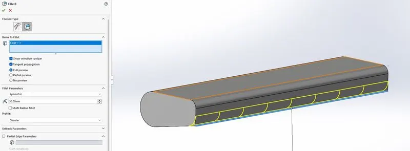
- Fillet: The fillet command is used to create rounded edges between the adjacent lines and faces in 2D and 3D. It is also used to connect two tangent arcs in 2D.
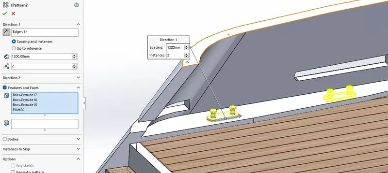
- Linear Pattern: The linear Pattern command consists of Circular pattern, Curve driven pattern, sketch driven pattern this tool help us to create more similar part or object concerning the original object and is used to create a different number of instances required to create pattern linearly.
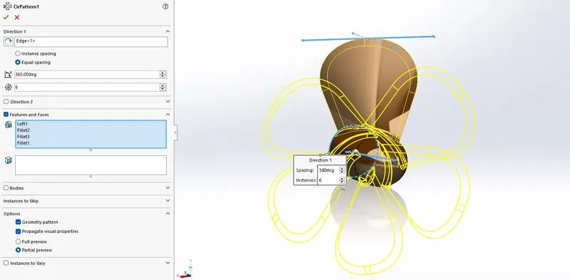
- Circular Pattern: Circular Pattern command is used to create a different number of instances required to create patterns circularly.
- Draft: This command is used to giving draft or slope of angle provide on body or part.
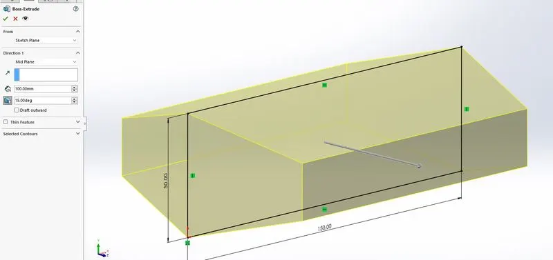
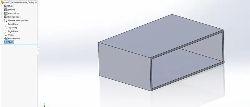
- Shell: The Shell command converts a 3D solid into a hollow shell with a wall of wanted thickness.
Modeling Tools:
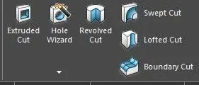
- Extruded Cut: This Command is used to removes material from the part. or select the part which will not be required in the selected contour.
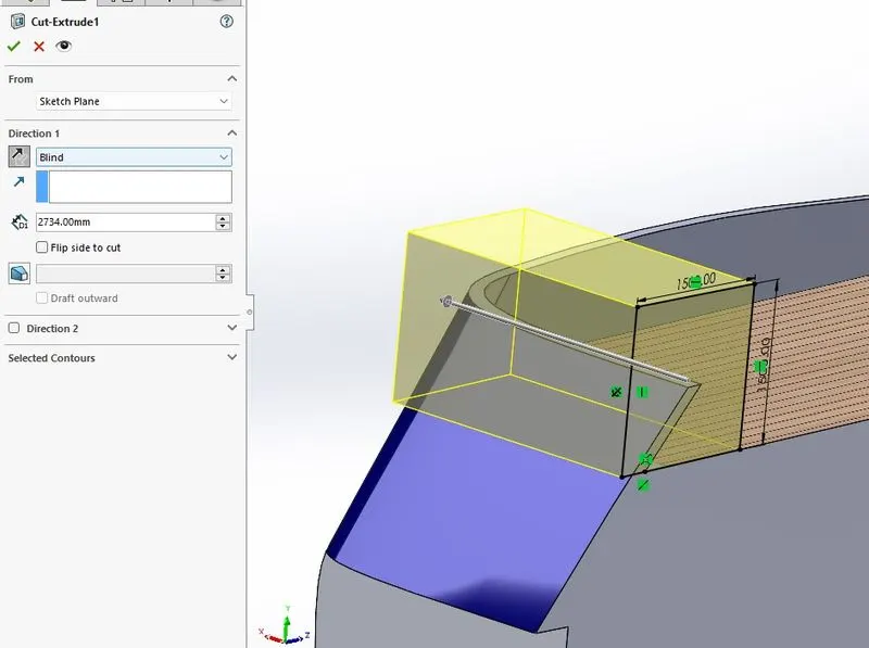
- Revolved Cut: This command is used to remove the material concerning the axis. Revolved Cuts follow the same process, except they cut away material instead of adding it.
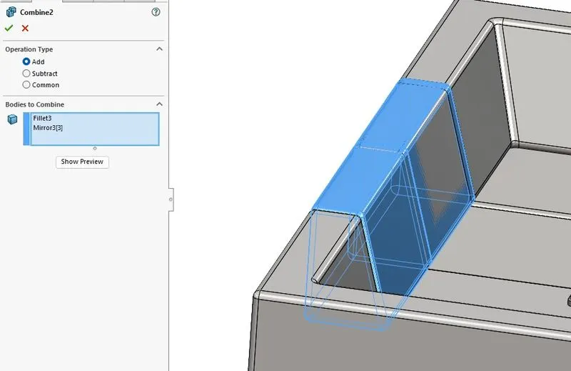
- Combine: This feature is used to combines multiple models into a single model without repositioning the models or adding bonds.
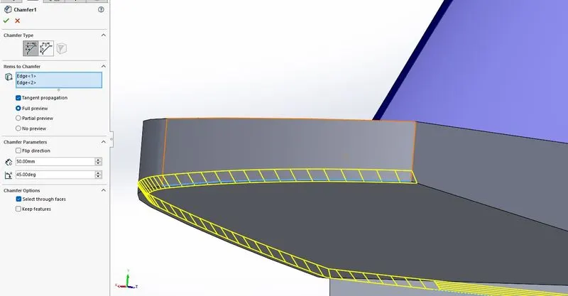
- Chamfer: This feature is used or to create slanted edges. We are required to select the two adjacent lines to create a chamfer between them and We can create the chamfer by specifying either the chamfer distance or angle.
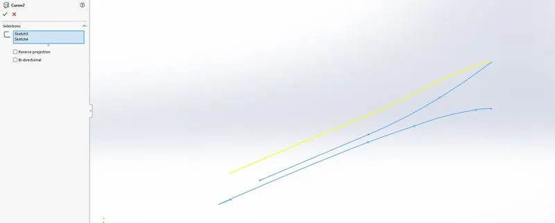
Project Curve: Project curve, well it is a tool you are going to use to form 3D curves from two 2D curves from two different planes. we need to do is basically select the two curves we drew and it will form a 3D Curve based on the curves we selected.
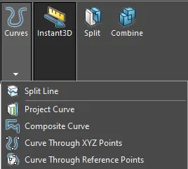
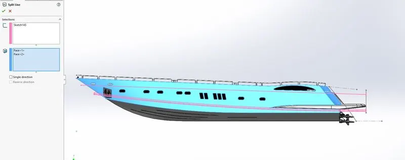
- Split Line: A split line is a tool that projects an entity (sketch, solid, surface, face, plane, or surface spline) to surfaces or curved or planar faces. It divides a selected face into multiple separate faces.
Surface Features Description:
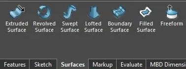
- Surface Tools: Surfacing tools are similar to solid tools but this tool creates surfaces instead of solid bodies. Surface tools like (Lofted surface, Swept surface, Surface trim, Boundary surface, Extruded Surface)
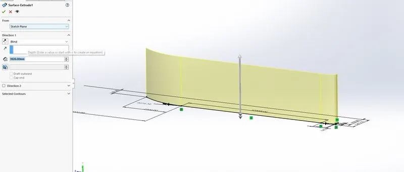
- Extruded Surface: This tool is used for extruding or extend the surface which was already created. we can extend the same surface with this tool or extend the surface which is tangent.
- Lofted Surface: Loft Surfaces are surfaces generated by multiple 3D Curves or existing edges creating a smooth tangency between the selected curves. Match Points are created between each selection denoting the orientation and path of the loft surface.
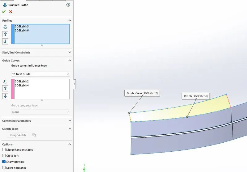
- Boundary Surface: Surface boundaries are defined from closed polygons, such as a closed polyline or a parcel, or surfaces.
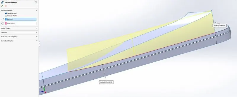
- Swept Surface: Sweep Surfaces are surfaced that are generated from a section curve positioned along a path. Parallel Sweep is defined as a section curve moving along a guide path while maintaining the section curve to be parallel to the guide path.
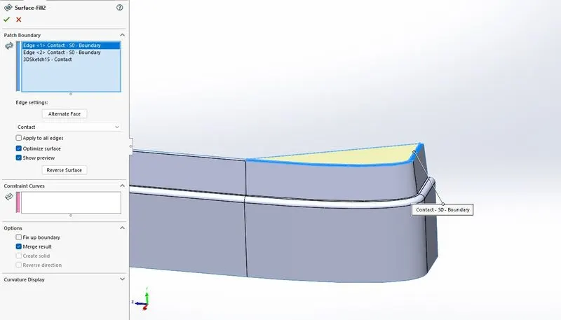
- Surface Fill: The Filled Surface feature constructs a surface patch with any number of sides, within a boundary defined by existing model edges, sketches, or curves, including composite curves. You can use this feature to construct a surface to fill a gap in a model.
Modeling Tools:
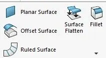
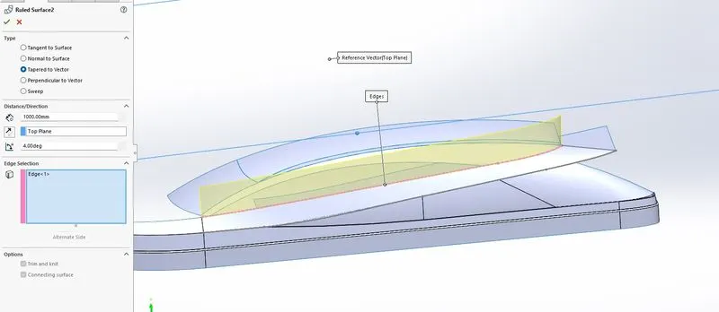
- Ruled Surface: A ruled surface can be described as the set of points swept by a moving straight line. For example, a cone is formed by keeping one point of a line fixed whilst moving another point along a circle. A surface is doubly ruled if through every one of its points there are two distinct lines that lie on the surface.
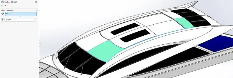
- Offset Surface: The surface can be offset from the reference mesh by points or by a fixed distance, and additional options for offsetting points can be adjusted once the surface has been created.
- Design methodology:
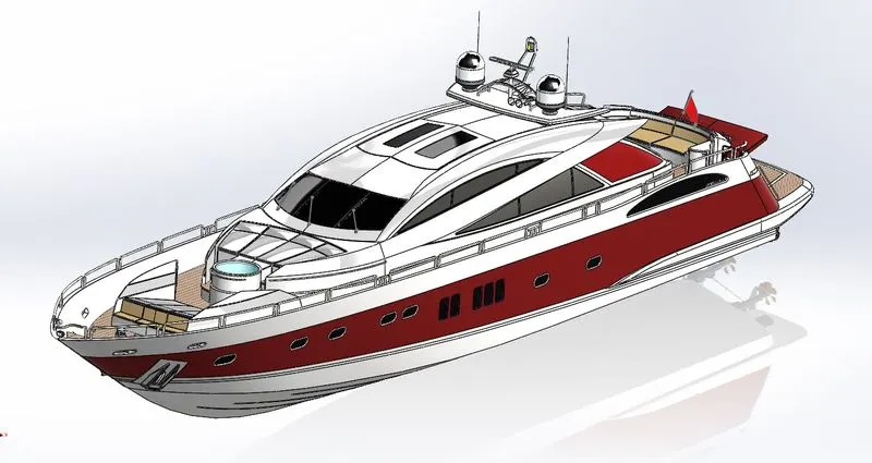
Following parts are designed and assembled in Solidworks
- Propeller
- Radar
- Hull
- Garage Door
- Front Seat
- Middle Seat
- Rear Seat
- Superstructure
- Radar Mast
Note to self: While designing any part, design constrained should use properly and make sure the sketch is fully defined then move further. Don't over define the sketch.
1. Propeller
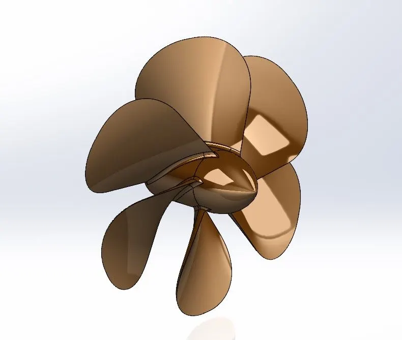
A propeller is a device with a rotating hub and radiating blades that are set at a pitch to form a helical spiral, that, when rotated, exerts linear thrust upon a working fluid, such as water or air. Propellers are used to pump fluid through a pipe or duct or to create thrust to propel a boat through water or an aircraft through the air. The blades are specially shaped so that their rotational motion through the fluid causes a pressure difference between the two surfaces of the blade by Bernoulli's principle which exerts a force on the fluid.
Features used for making Propeller:
- Revolve Boss/Base
- Lofted Boss/Base
- Cut Extrude
- Fillet
- Circular Pattern
2. Radar
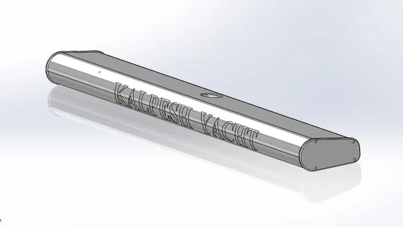
Radar will show what is around the yacht, seeing through the darkness, precipitation, and poor visibility. Whether you’re crossing a busy shipping channel in thick fog, looking for squalls offshore, or identifying a harbor entrance in the dark, Radar offers significant aid to navigation and safety.
Features used for making Radar:
- Extruded Boss/Base
- Cut Extrude
- Fillet
- Sketch Pattern
- Split Line
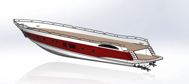
3. Hull
The body of a boat is called its hull. At the upper edges of the boat's hull are the gunwales. The gunwales provide extra rigidity for the hull. The cross-section of the stern, where you attach an outboard motor, is called the transom. A hull is the watertight body of a ship, boat, or flying boat. The hull may open at the top (such as a dinghy), or it may be fully or partially covered with a deck. Atop the deck may be a deckhouse and other superstructures, such as a funnel, derrick, or mast.
Features used for making Hull:
- Projected Curve
- Lofted Surface
- Surface Trim
- Cut Extrude
- Extruded Boss/Base
- Knit Surface
- Swept Surface
- Fillet
- Linear Pattern
- Split Line
- Helix/Spiral
- Split Line
- Offset Surface
- Mirror
- Chamfer
3. Garage Door
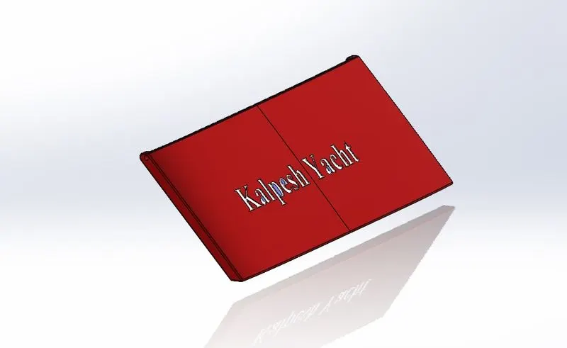
The garage door of our yacht is for protecting or placed our car or bike on the backside of our yacht while traveling in the yacht.
Features used for making Garage Door:
- Extruded Boss/Base
- Cut Extrude
- Fillet
- Mirror
- Chamfer
- Shell
4. Front Seat
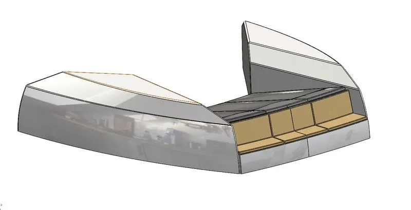
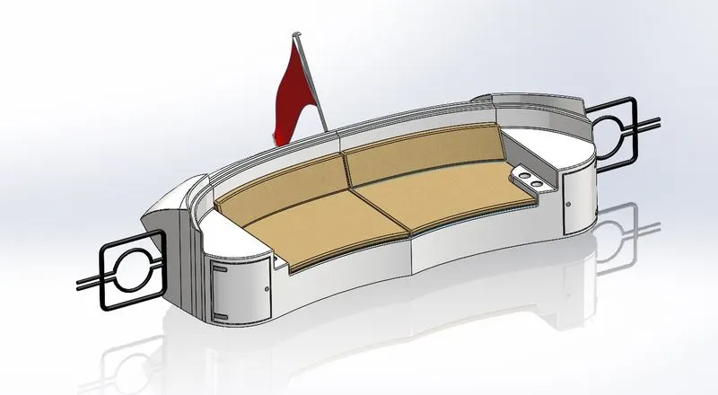
This is the Front Seat of our yacht which is located on the front side which having very awesome looks and comfortable yacht seats for passengers.
Features used for making Front Seat:
- Sweep Surface
- Extruded Surface
- Surface Fill
- Lofted Surface
- Trim Surface
- Revolved Surface
- Chamfer
- Mirror
- Knit Surface
5. Middle Seat
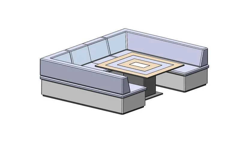
This is the middle Seat of our yacht which is located on the mid-side which having very awesome looks and comfortable yacht seats for passengers with tables for dinner or lunch with having a wonderful sea experience on the yacht.
Features used for making Middle Seat:
- Extruded Boss/Base
- Chamfer
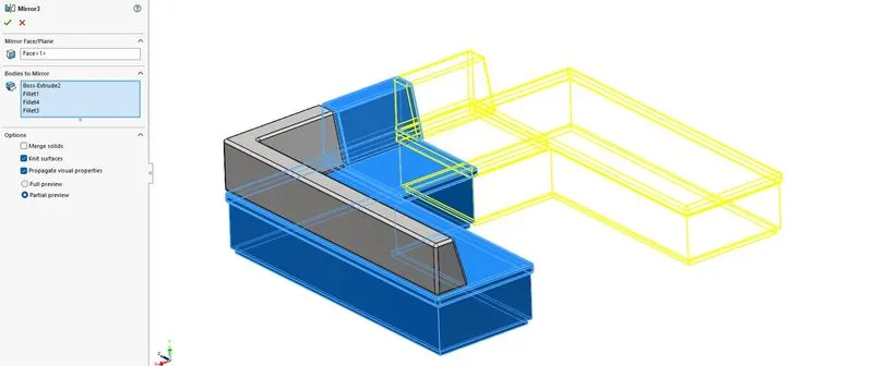
- Mirror
- Fillet
- Combine
6. Rear Seat
This is the Rear Seat of our yacht which is located on the rear side which having very awesome looks and comfortable yacht seats for passengers with having a wonderful backside sea experience on the yacht.
Features used for making Rear Seat:
- Sweep Surface
- Extruded Surface
- Surface Fill
- Lofted Surface
- Trim Surface
- Revolved Surface
- Chamfer
- Mirror
- Knit Surface
- Ruled Surface
7. SuperStructure
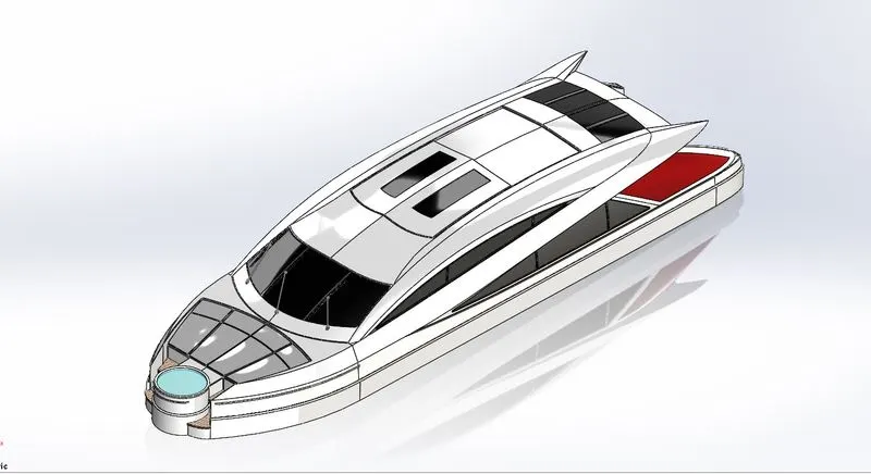
On watercraft, the superstructure consists of the parts of the ship or a boat, including sailboats, fishing boats, passenger ships, and submarines, that project above her main deck. This does not usually include its masts or any armament turrets. This Superstructure then assembles on the hull of the yacht. the part of a building or construction entirely above its foundation or basement. any structure built on something else. the overlying framework or features of an organization, institution, or system, built or superimposed on a more fundamental base.
Features used for making Superstructure:
- Projected Curve
- Ruled Surface
- Lofted Surface
- Surface Trim
- Cut Extrude
- Extruded Boss/Base
- Knit Surface
- Swept Surface
- Fillet
- Linear Pattern
- Split Line
- Helix/Spiral
- Split Line
- Offset Surface
- Mirror
- Chamfer
8. Radar Mast
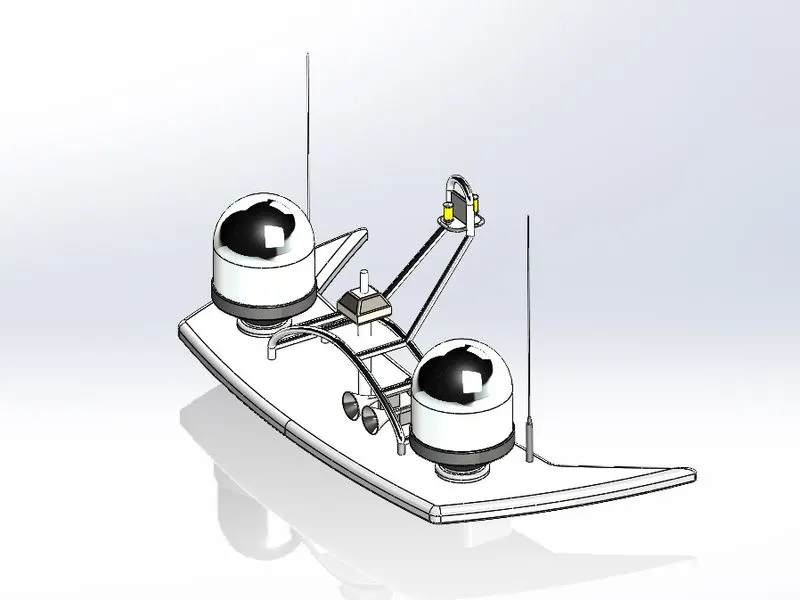
It does so by detecting other ships and land obstacles, to give bearing and distance for collision avoidance and navigation while on water. A marine radar device acts as a major navigation aid for boaters. It helps in detecting boats, birds, landmasses, and weather systems - even if the visibility is less than usual.
Features used for making Radar Mast:
- Extruded Boss/Base
- Revolved
- Sweep Surface
- Fillet
- Chamfer
- Shell
- Dome
Assembly of Yacht
After all 8 parts are modeled we have to go to the assembly section of Solidworks to assemble these Yacht parts.
- After adding materials we choose the assembly section for mating of our Yacht parts like Hull, Radar, Propeller, Superstructure, Front middle rear seats, radar mast, etc.
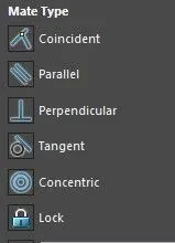
- For mating and assembly on Yacht components, we use mating-type like Coincident, Parallel, etc.
- Mating Types:
- Coincident: A coincident constraint causes two points to coincide, or a point to lie anywhere on an object or the extension of an object.
- Parallel: In geometry, parallel lines are lines in a plane that do not meet; that is, two straight lines in a plane that do not intersect at any point are said to be parallel.
- Concentric: Circle those having a common center or the same point.
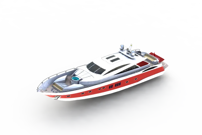
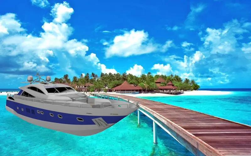
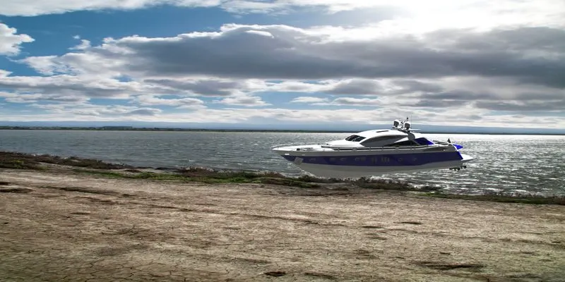
- Rendering: Rendering or image synthesis is the process of generating a photorealistic or non-photorealistic image from a 2D or 3D model utilizing a computer program. The resulting image is referred to as the render.
- PhotoView 360: PhotoView 360 is a visualization and rendering solution included with SOLIDWORKS Professional and SOLIDWORKS Premium. Providing a highly interactive environment for viewing designs as well as for creating photo-realistic renderings that can be used to showcase your designs.
- Solidworks Visualize: SOLIDWORKS® Visualize allows you to leverage your 3D CAD data to create photo-quality content in the fastest and easiest way you can–from images to animations, interactive web content, and immersive Virtual Reality.