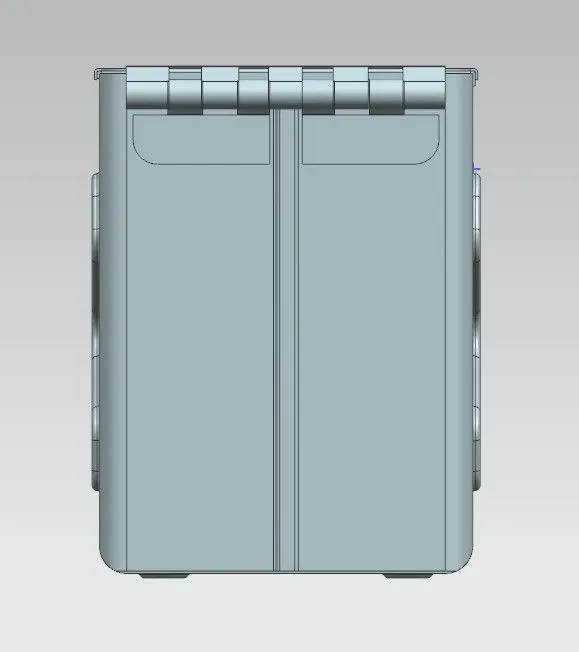
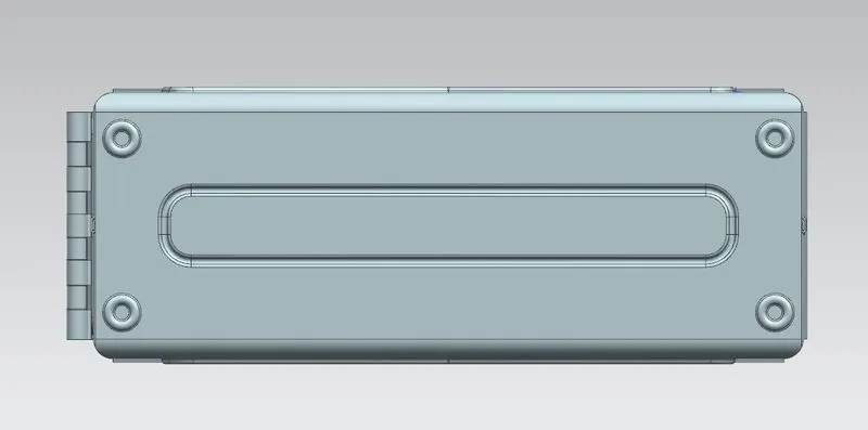
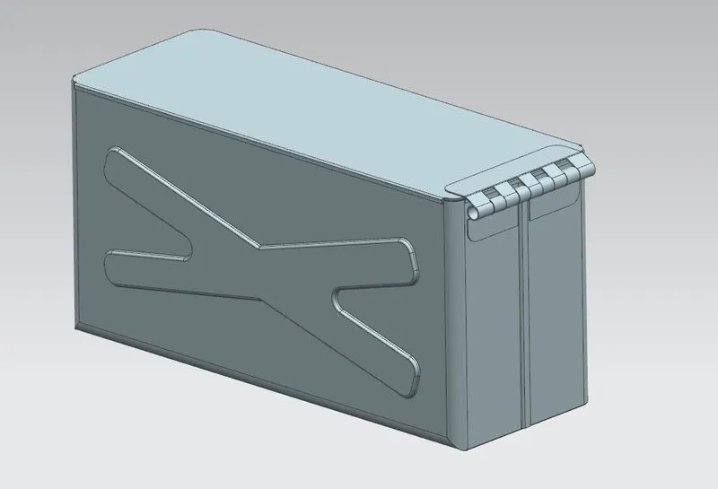
Advanced Sheet Metal Design Using NX Cad Challenge_2_Box Assembly
Sheet Metal Box Assembly using NX Cad
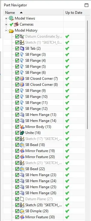
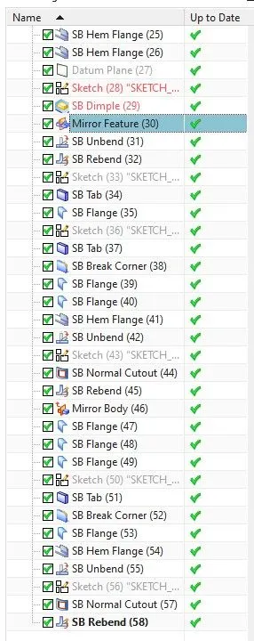
Objective: Creating Box Assembly in NX using Sheet Metal. In this Model, we use some New features like Hem Flange, Corner, Mirror along with Tab, Bead, Dimple, Bend, Unbend, etc.
Introduction: Sheet metal is metal formed by an industrial process into thin, flat pieces. Sheet metal is one of the fundamental forms used in metalworking, and it can be cut and bent into a variety of shapes. Countless everyday objects are fabricated from sheet metal. Thicknesses can vary significantly; extremely thin sheets are considered foil or leaf, and pieces thicker than 6 mm (0.25 in) are considered plate steel or "structural steel".
Features we Used in Box Assembly Design:
1. Tab Features: It is similar to Extrude Feature. We can use Set parameter values or we can also be able to use Local values which we needed. To Execute this command base profile sketch is required. In this tab feature, we draw a rectangle of 150mmx200mm Dimension. And use 1mm Thickness of Tab.
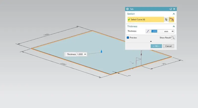
2. Flange: This feature is used to get flanged at the planer face we have to select the edge where we want flange we can control bend radius, Length, Angle of flange direction where we want also we can choose where we want to flange outside or inside of the material to proper use of sheet metal in Industries. For creating Box we create 200mm length of Flange at 2edges of our tab.
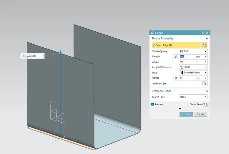
Then we created another 2 flanges on another edge of our tab of 70mm in length.
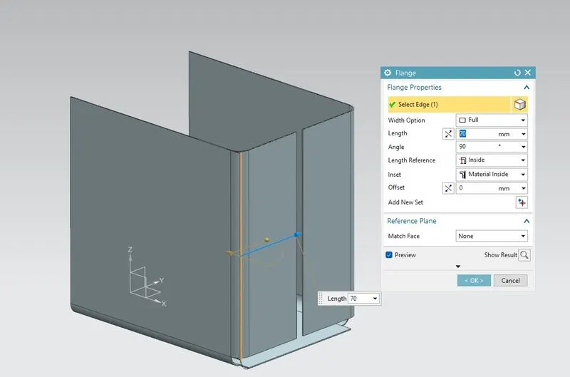
3. Close corner: To close the remaining bottom portion of our box we use the close corner feature to close the corner of the flange concerning the tab at the bottom.
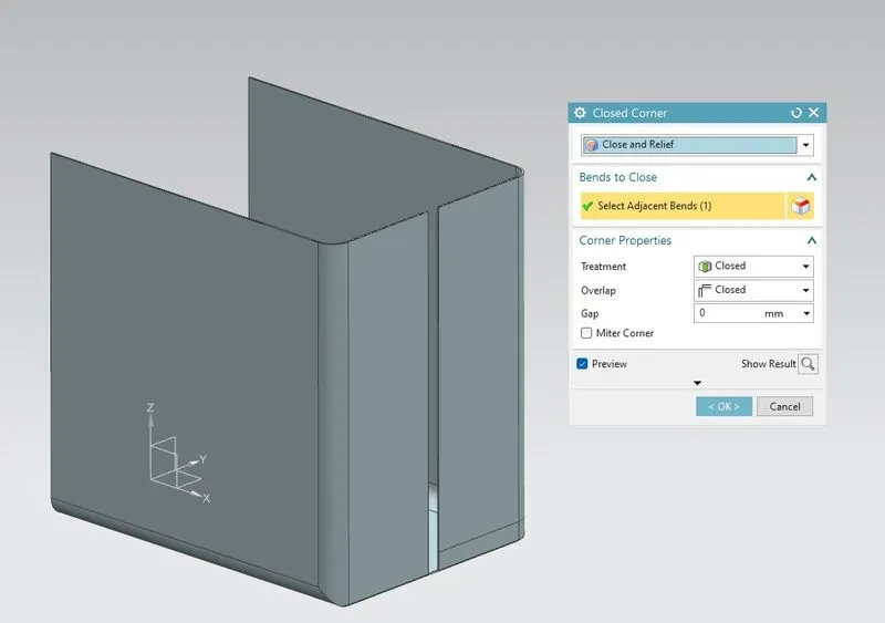
4. Hem Flange: Before we use hem flange we created 2 flanges for locking of flanges we created two more flanges with 0.02mm and another with 6.5mm of the flange. Then we created a hem flange at that two flanges for box assembly with 0.5mm of bend radius and 3.5 mm flange length.
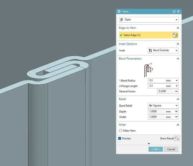
5. Mirror: Then we mirrored this one side of the box assembly.
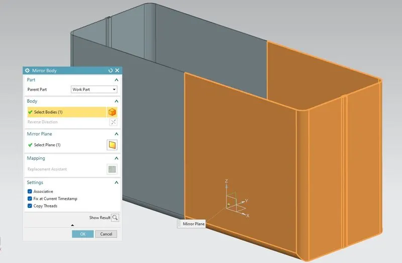
6.Unite: After using the mirror feature to combine the two or more solid bodies into a single body we use unite feature which is similar to the combine feature.
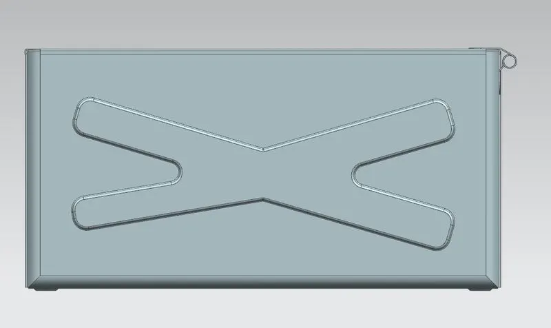
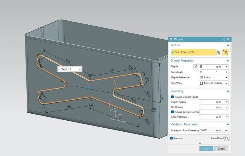
7. Dimple: For our box assembly we created an X shape sketch on one side of the box then we use a Dimple feature with a depth of 2mm. Then we mirrored it to another side also. To Give looks to our Box.
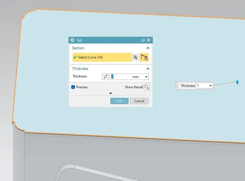
After creating this we have to create a lid to our box assembly to lock our box that firstly we have to create a datum plane about 201mm of the box then we create a sketch with respect to the edges of our box and crate tab of 1mm of thickness.
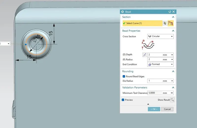
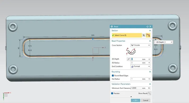
8. Bead: Then we created a bead of 15mm at the bottom face of our box and mirror it to another four side corner of the box. We created another bread at the center of the box on the bottom side with 320mmx40mm in dimension with a bead depth of 2mm.
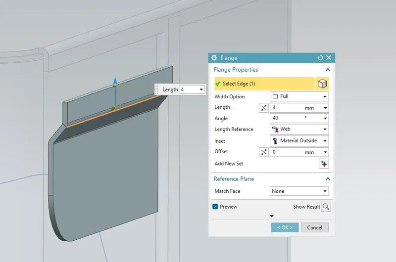
9. Tab and Flange: Then we created a 1mm thickness of tab feature on a side face of Box and crate flange at edge of tab having 40deg in angle. And use break corners of radius 10mm to eliminate the sharp edges of the tab which we have created.
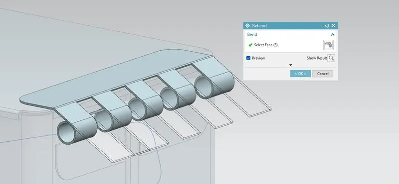
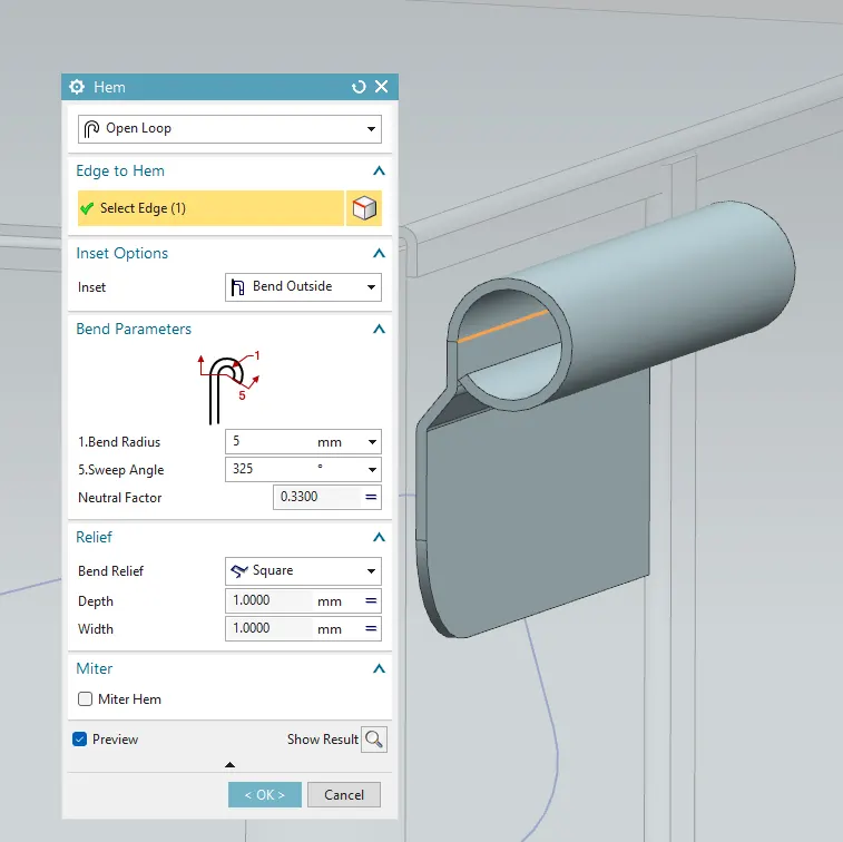
10. Hem Flange: Then we create another hem flange of open-loop type with a radius of 5mm and sweep angle of 125 deg.
Then we unbend this hem flange and create a sketch and use a normal cutout to get the desired cutout on the hem flange. And again rebend it.
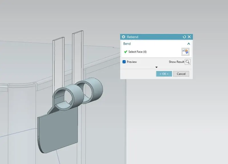
and we use the mirror command to mirror this hinge feature on another side.
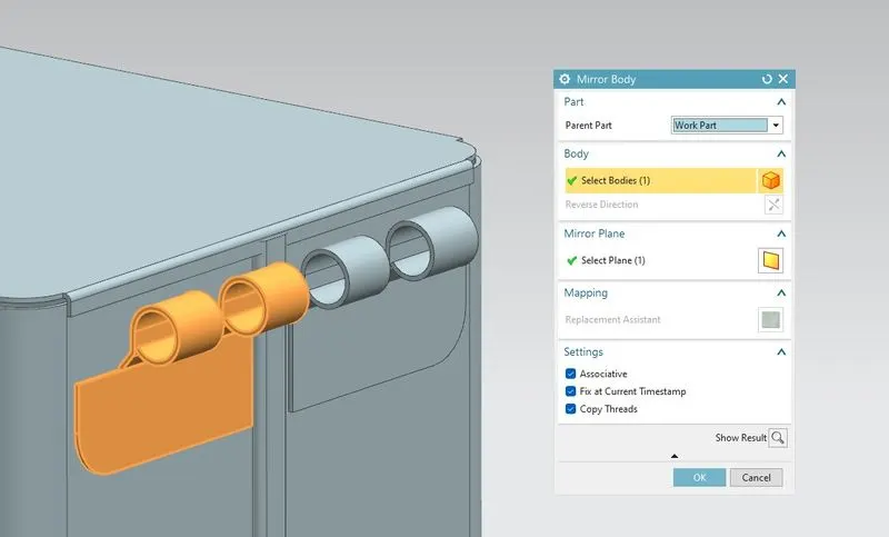
To complete this hinge lock to the top lid of the box we follow the same feature to create this and we completed our box assembly succesfully.