Week 11- Assembly Workbench
Assembly Workbench
Quick return mechanism
A quick return mechanism is an apparatus to produce a reciprocating motion in which the time taken for travel in return stroke is less than in the forward stroke. It is driven by a circular motion source (typically a motor of some sort) and uses a system of links with three turning pairs and a sliding pair. A quick-return mechanism is a subclass of a slider-crank linkage, with an offset crank.
Quick return is a common feature of tools in which the action is performed in only one direction of the stroke, such as shapers and powered saws, because it allows less time to be spent on returning the tool to its initial position.
Applications
Quick return mechanisms are found throughout the engineering industry in different machines:
- Shaper
- Screw press
- Power-driven saw
- Mechanical actuator
- revolver mechanisms
Design
The disc influences the force of the arm, which makes up the frame of reference of the quick return mechanism. The frame continues to an attached rod, which is connected to the circular disc. Powered by a motor, the disc rotates and the arm follows in the same direction (linear and left-to-right, typically) but at a different speed. When the disc nears a full revolution, the arm reaches its furthest position and returns to its initial position at a quicker rate, hence its name. Throughout the cut, the arm has a constant velocity. Upon returning to its initial position after reaching its maximum horizontal displacement, the arm reaches its highest velocity.
The quick return mechanism was modeled after the crank and slider (arm), and this is present in its appearance and function; however, the crank is usually hand powered and the arm has the same rate throughout an entire revolution, whereas the arm of a quick return mechanism returns at a faster rate. The "quick return" allows for the arm to function with less energy during the cut than the initial cycle of the disc.
Specifications
When using a machine that involves this mechanism, it is very important to not force the machine into reaching its maximum stress capacity; otherwise, the machine will break. The durability of the machine is related to the size of the arm and the velocity of the disc, where the arm might not be flexible enough to handle a certain speed. Creating a graphical layout for a quick return mechanism involves all inversions and motions, which is useful in determining the dimensions for a functioning mechanism. A layout would specify the dimensions of the mechanism by highlighting each part and its interaction among the system. These interactions would include torque, force, velocity, and acceleration. By relating these concepts to their respective analyses (kinematics and dynamics), one can comprehend the effect each part has on another.
Mechanics
In order to derive the force vectors of these mechanisms, one must approach a mechanical design consisting of both kinematic and dynamic analyses.
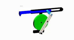
Quick Return Mechanism
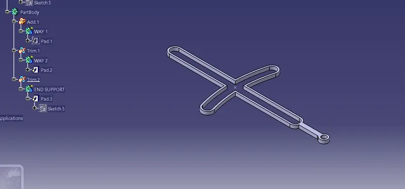
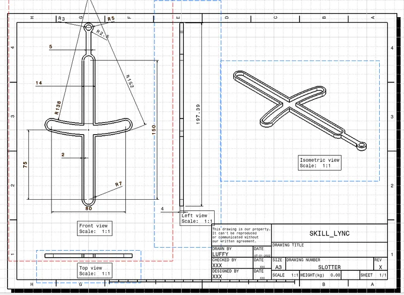
1. SLOTTER
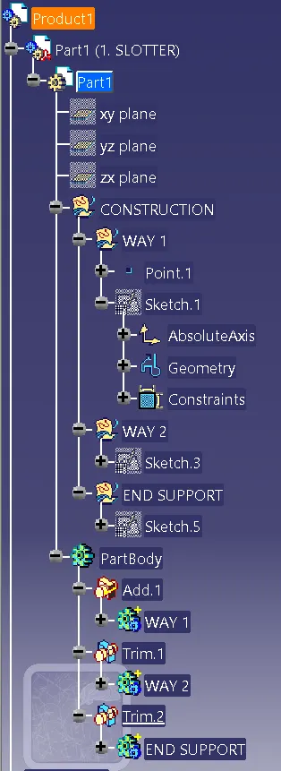
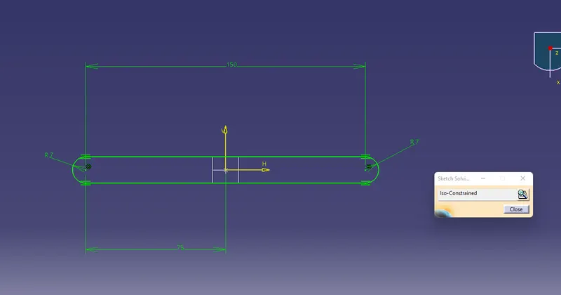
1. Slotter
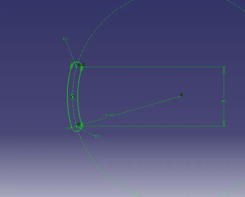
2. Slottwer Way 2
3. End Support
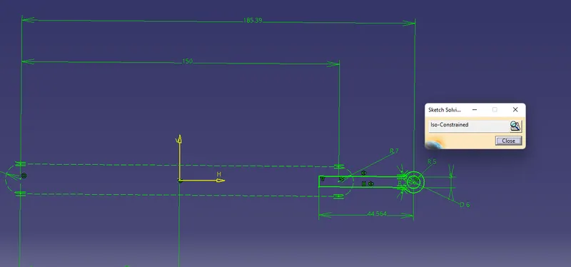
Now Pad and Give Thickness to All parts
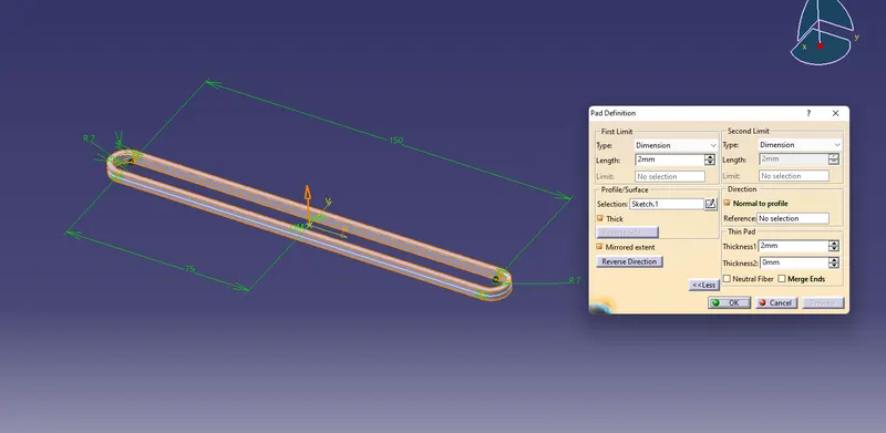
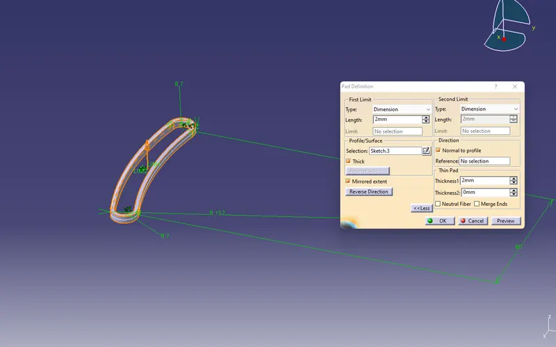
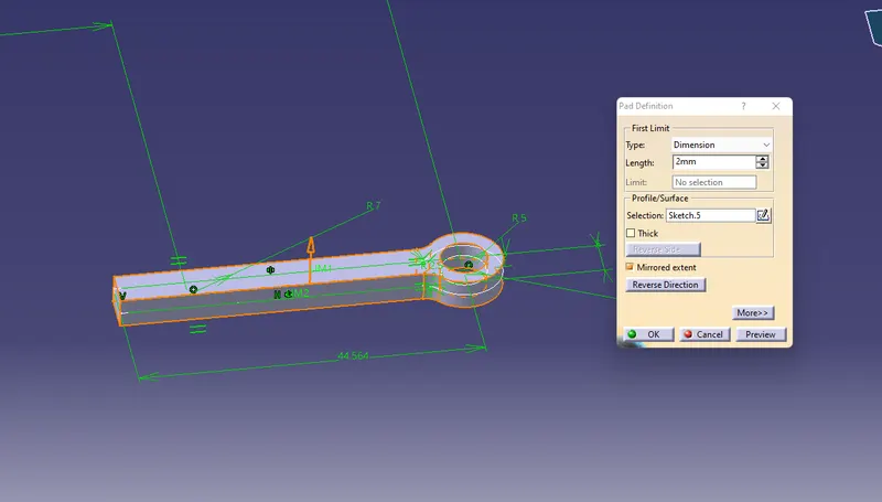
Now join and use Boolean Operation Like (Add & Trim) used
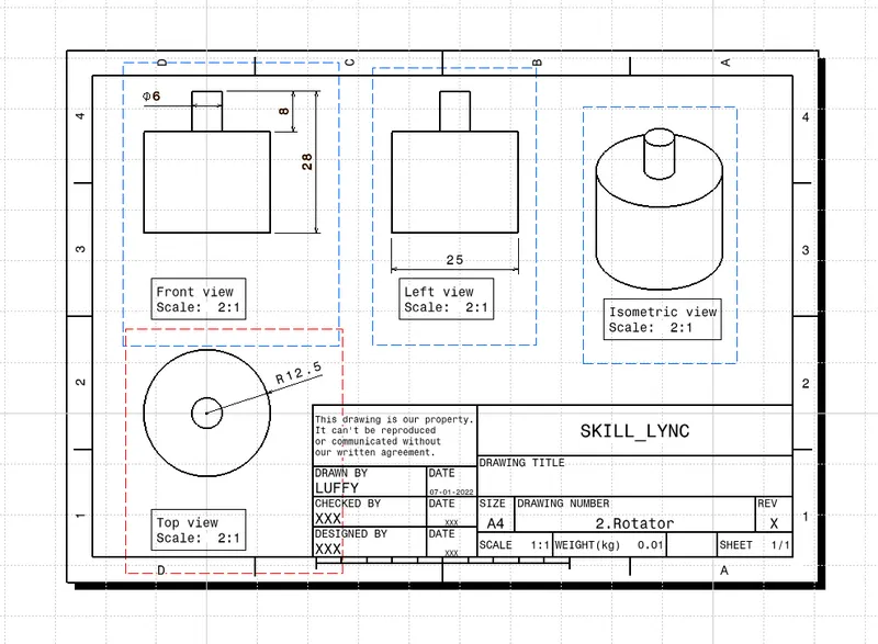
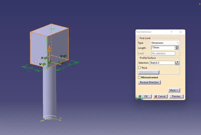
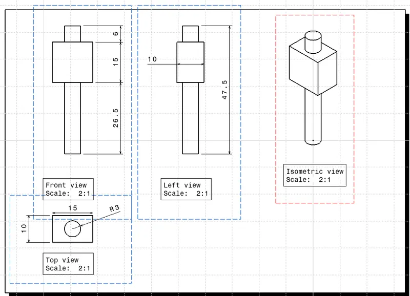
2. Rotator Block
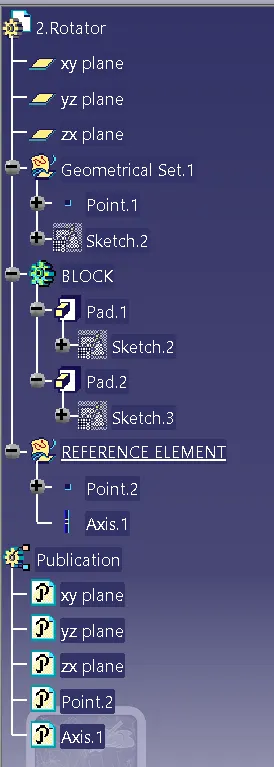
Base of Block
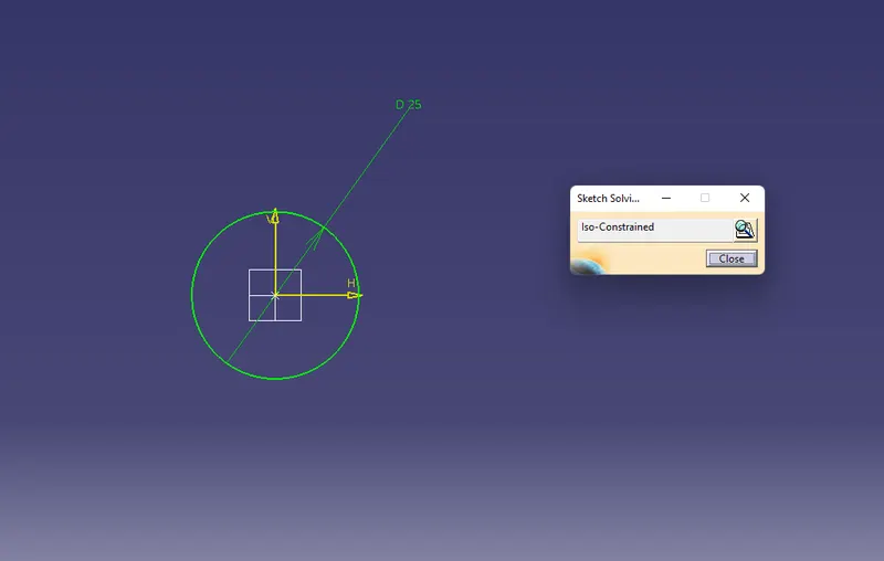
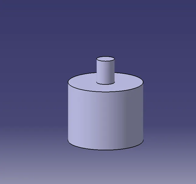
Pin On Block
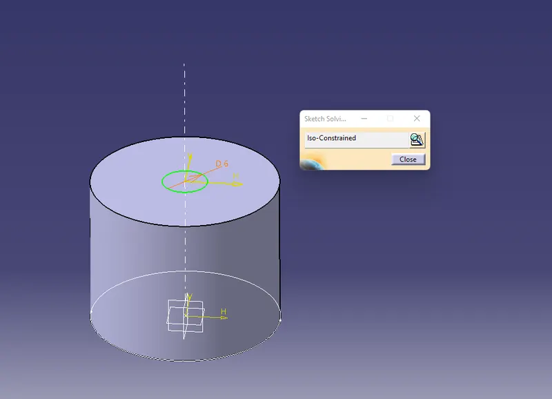
Use the Pad feature and join all solid bodies
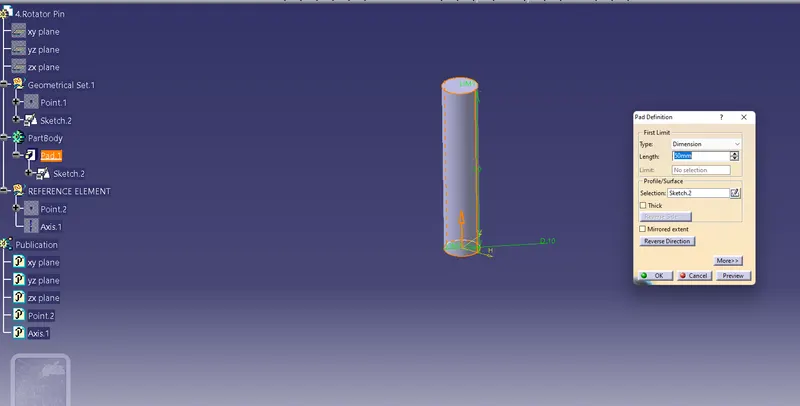
3. Rotating Pin
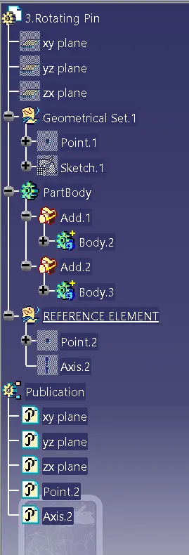
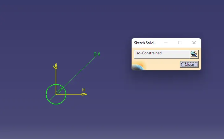
Use Pad Feature to make Solid Body
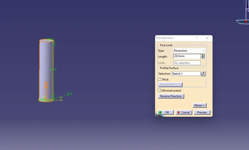
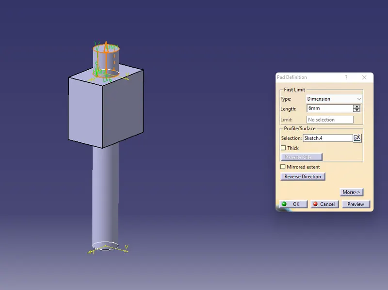
4. Rotator Pin
5. Slider
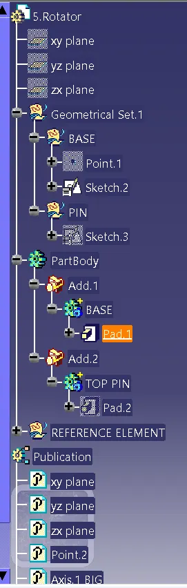
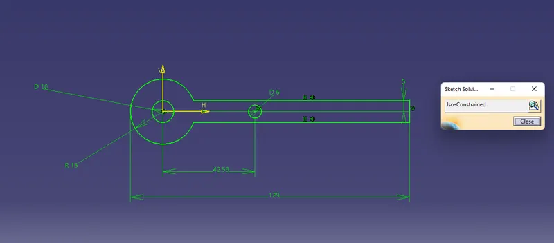
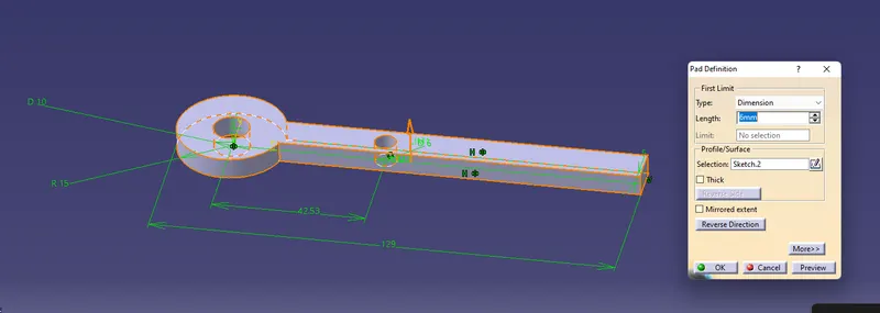
Add small pin on top and use Add operation to join
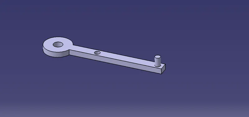
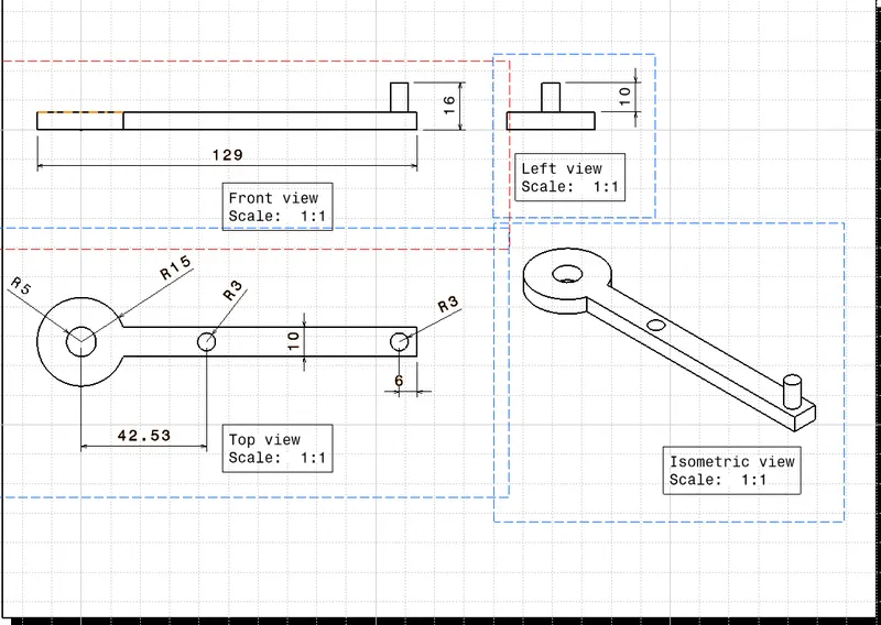
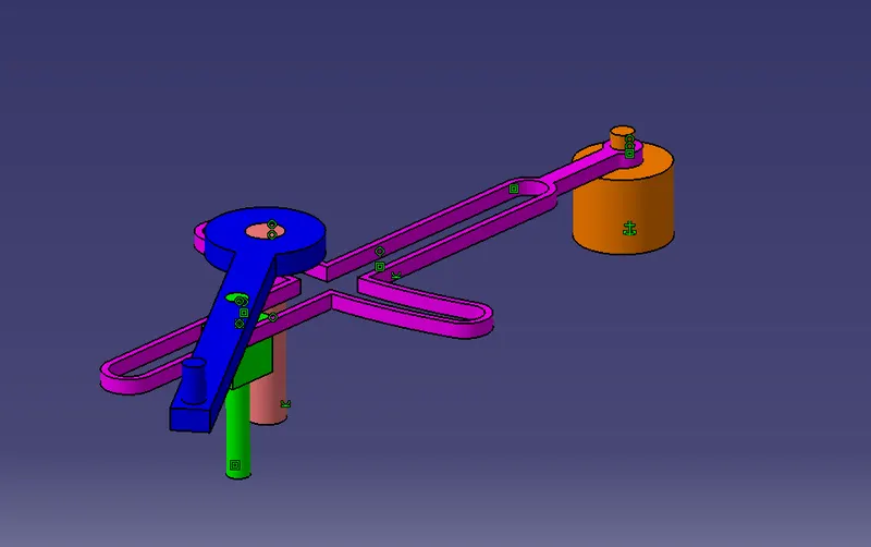
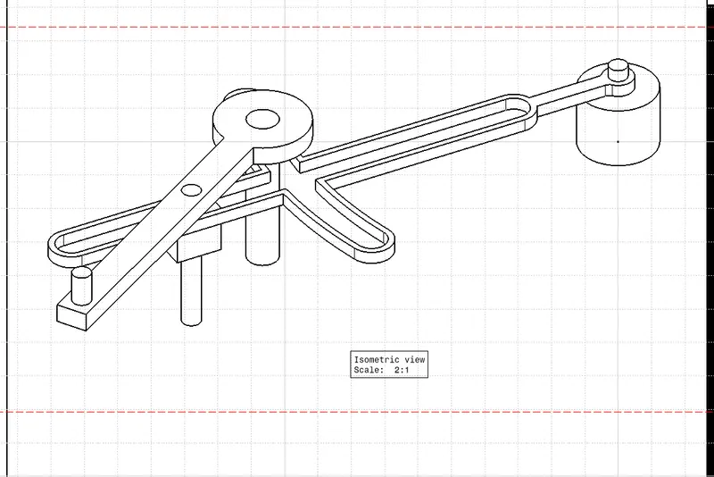
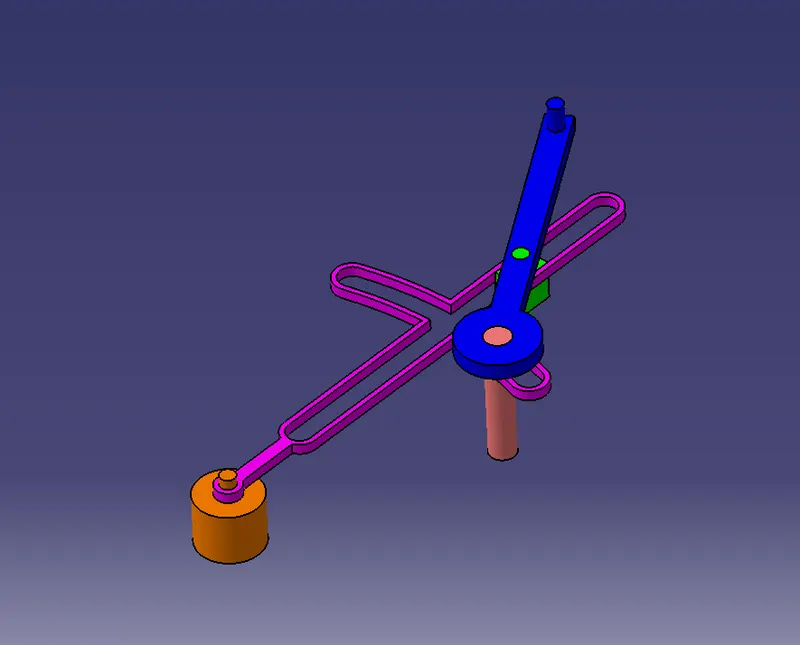
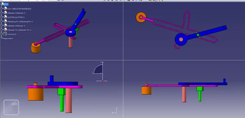
Now Assemble all parts together of Quick Return Mechanism
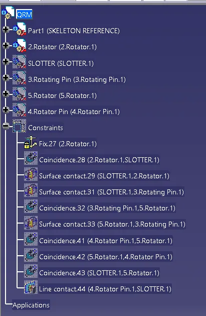
Fix the Rotator
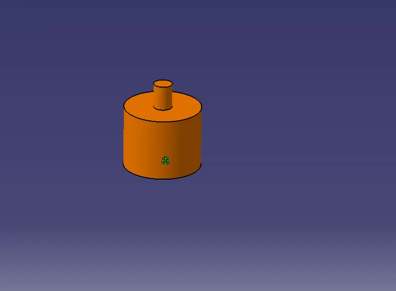
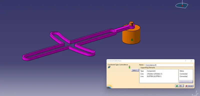
Use Coincidence command for Rotator and Slotter
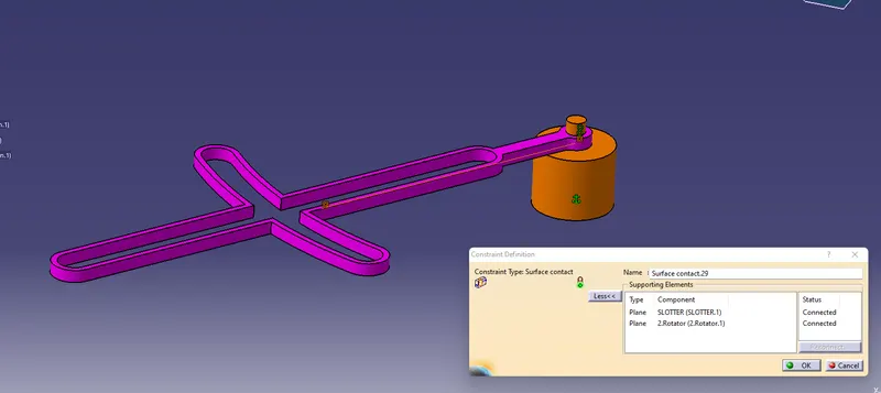
Make Surface contact between two
now make surface contact between slotter and mechanism pin
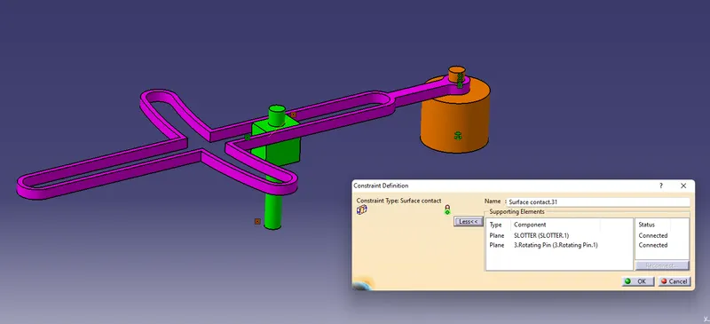
Use Coincidence between Rotator and Rotating Pin
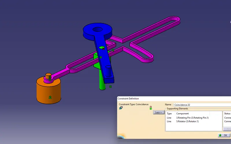
make surface contact between both
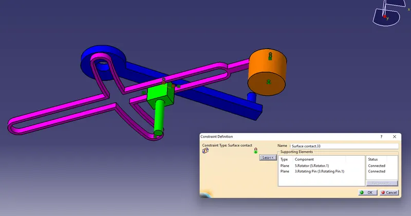
coincidence between rotator and rotator pin
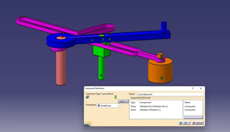
Surface contact between Slotter and Rotator
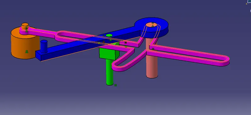
Assembly of QRM
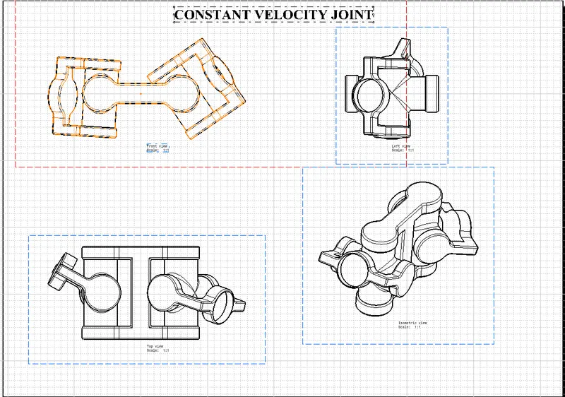
2. CONSTANT VELOCITY JOINT
Constant-velocity joints (also known as homokinetic or CV joints) allow a drive shaft to transmit power through a variable angle, at constant rotational speed, without an appreciable increase in friction or play. They are mainly used in front wheel drive vehicles. Modern rear wheel drive cars with independent rear suspension typically use CV joints at the ends of the rear axle halfshafts and increasingly use them on the drive shaft.
Constant-velocity joints are protected by a rubber boot, a "CV gaiter", usually filled with molybdenum disulfide grease. The six spheres are bounded by an anti-fall gate that prevents the spheres from falling when the shaftings are perfectly aligned. Cracks and splits in the boot will allow contaminants in, which would cause the joint to wear quickly as grease leaks out. (Parts in contact would not get proper lubrication, small particulates would cause damage and scratching, while water ingress causes metal components to rust and corrode.) Wear of the boot often takes the form of small cracks, which appear closer to the wheel, because the wheel produces most of the vibration and up and down motions. Cracks and tears in the areas closer to the axle are usually caused by external factors, such as packed snow, stones or uneven rocky off-road paths. Aging and chemical damage can also cause boot failure.
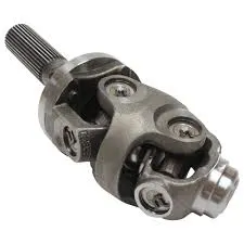
1. CROSS JOINT
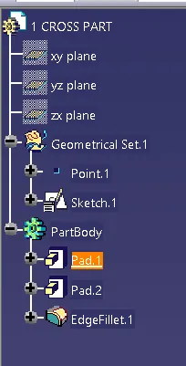
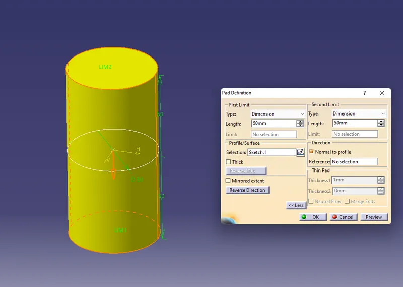
Draw a sketch of the hole with 50mm dia and Pad it 50mm Both side
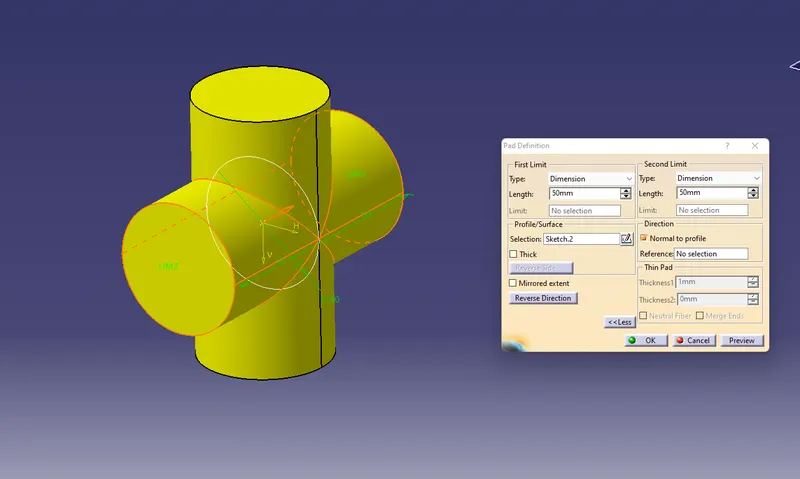
Draw the same dia circle and pad it 50mmm both the side
now give edge fillet of radius 5mm
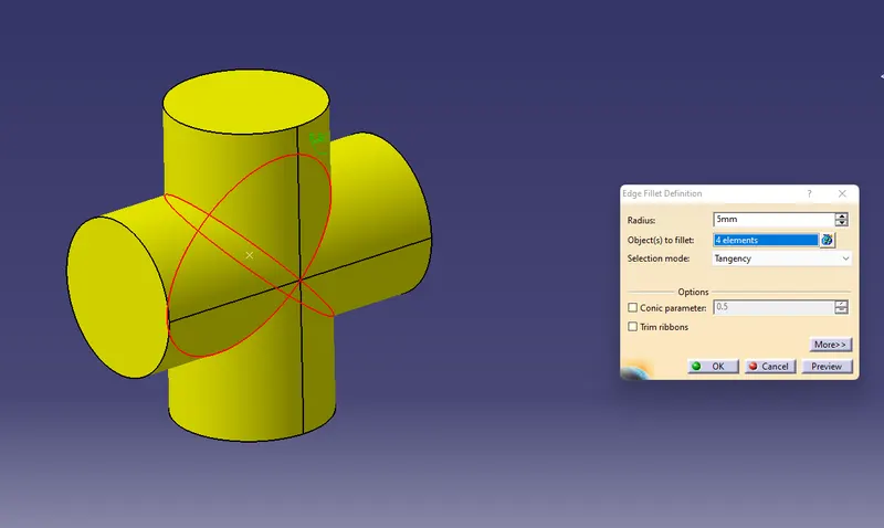
Cross Joint
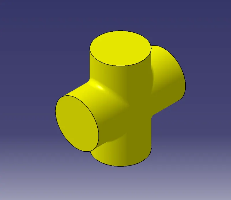
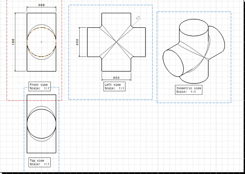
Part 2
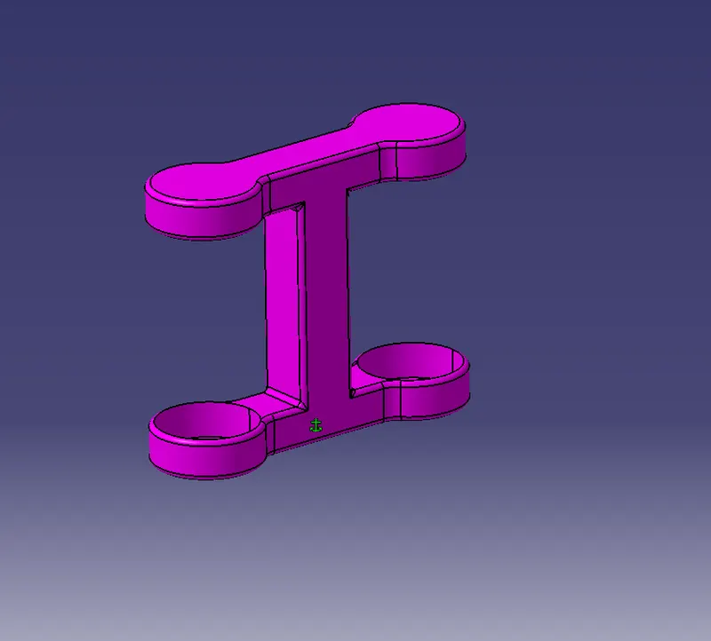
2. 4 WAY RING
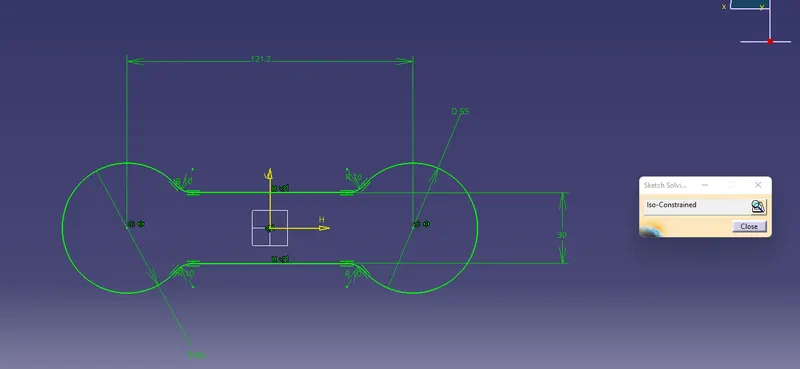
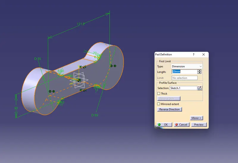
Pad it for 20mm
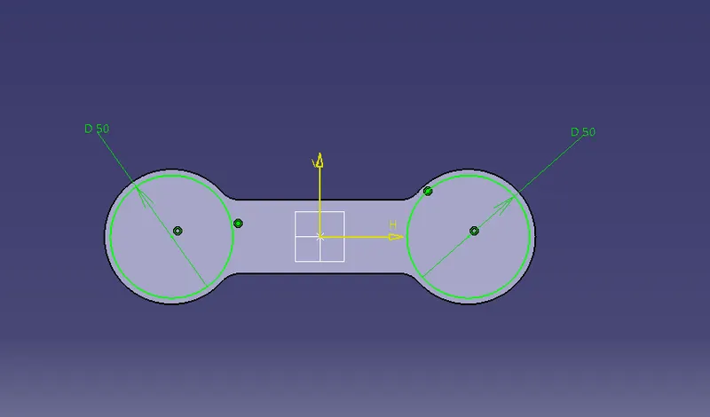
Create two 50mm dia of the hole to make cutouts
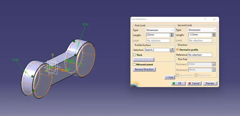
Pad it
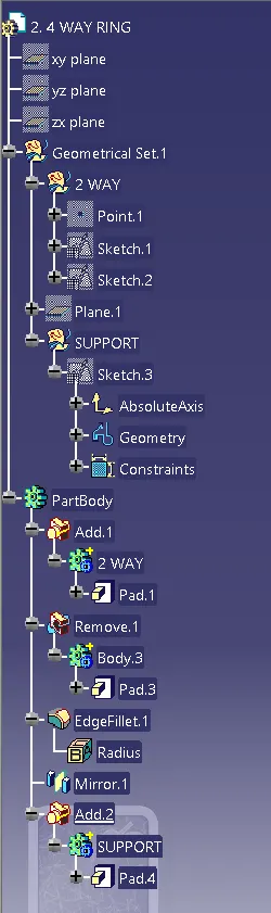
ADD both solid and then use remove boolean operation
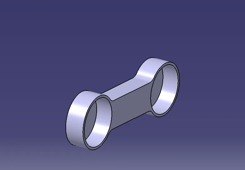
Give edge fillet of 2.5mm
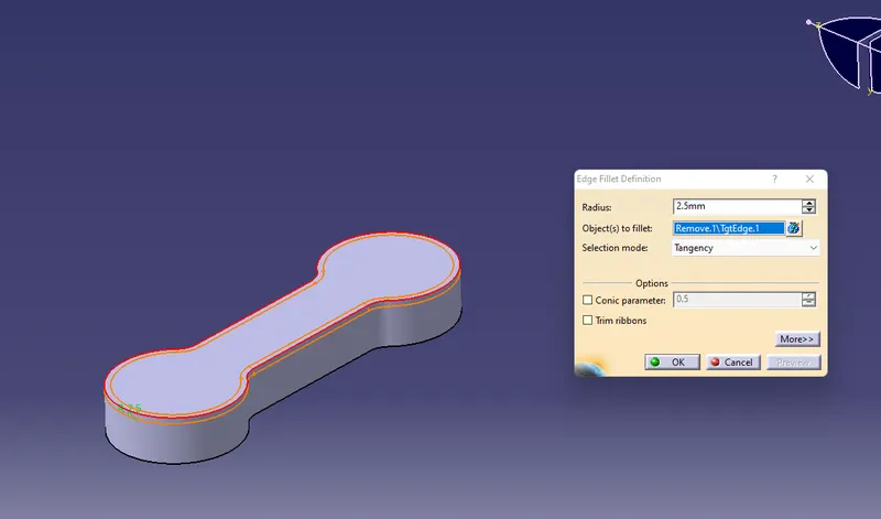
Mirror it to other side
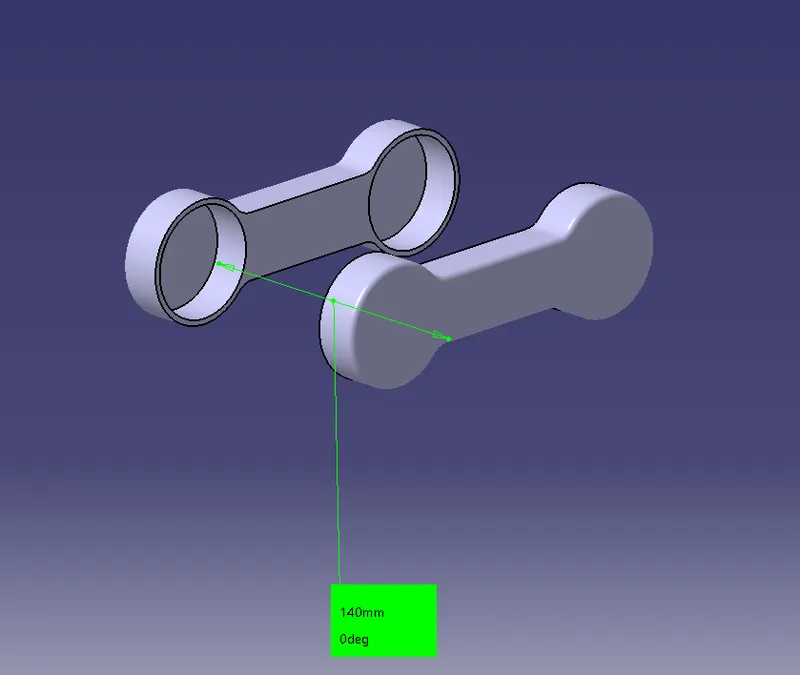
Now create support between two rings and use boolean operation add to merge solid bodies
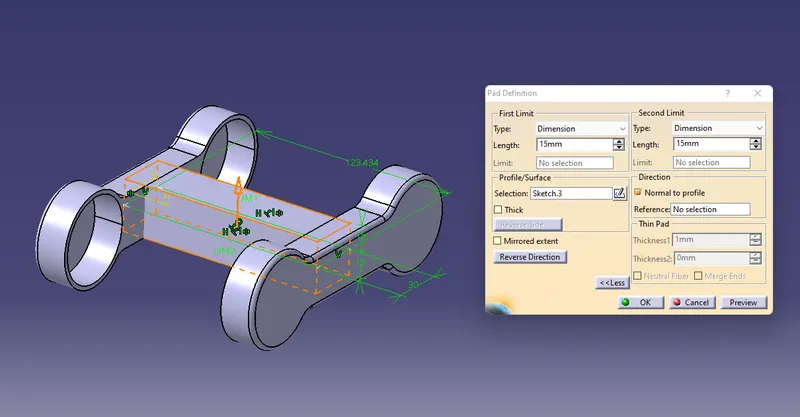
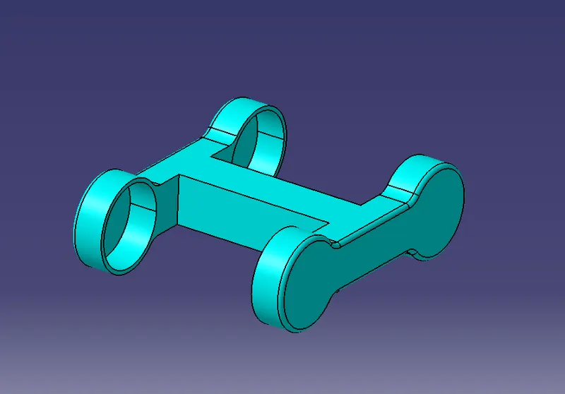
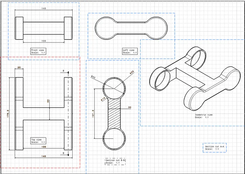
PART 3
3. 3 WAY HANDLE
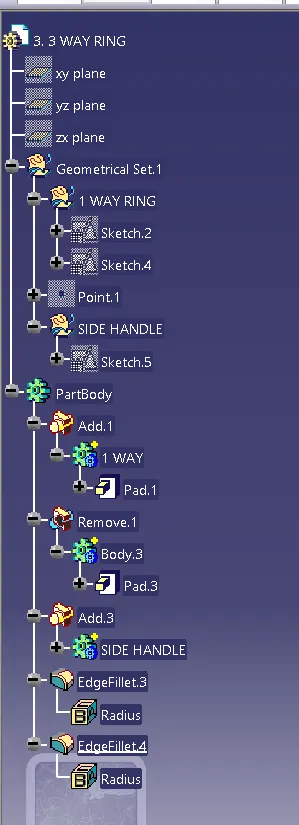
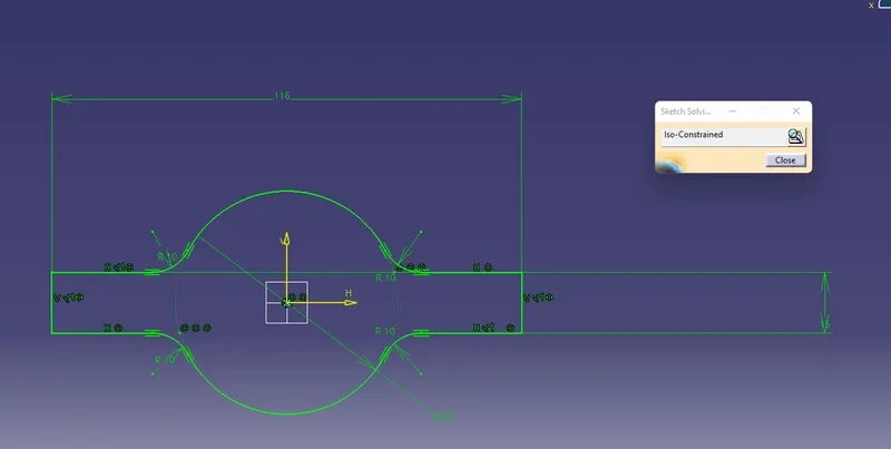
create sketch
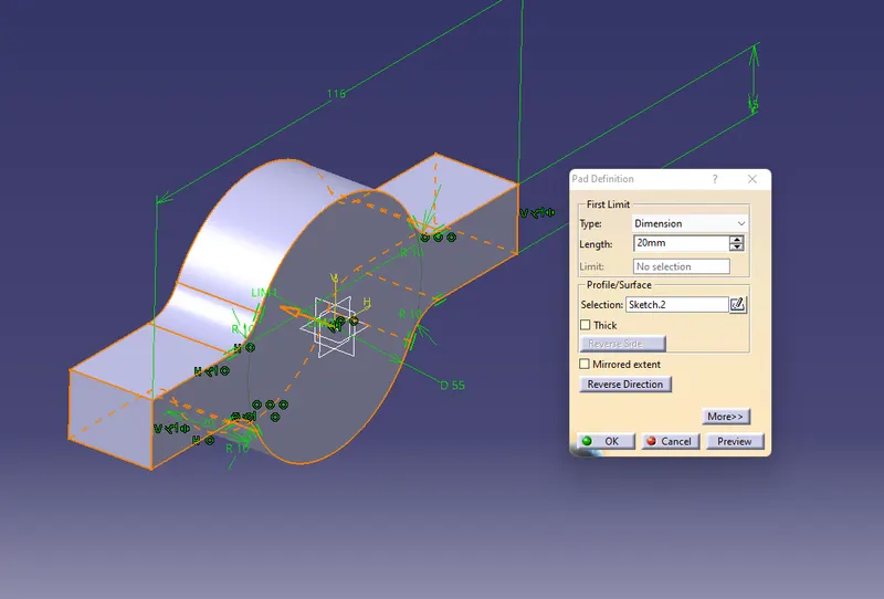
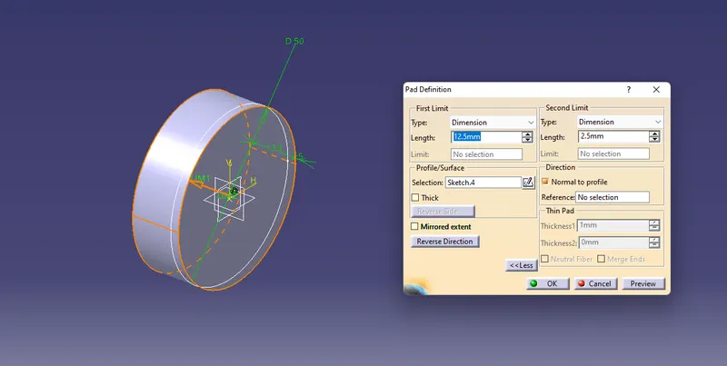
use add and remove command to create this cutout
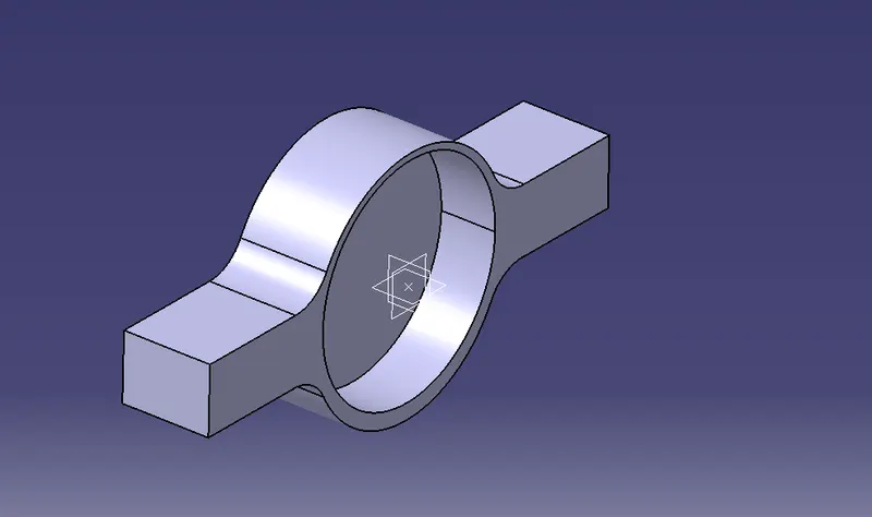
Create side handle pad it and then use mirror command to mirror on other side of handle
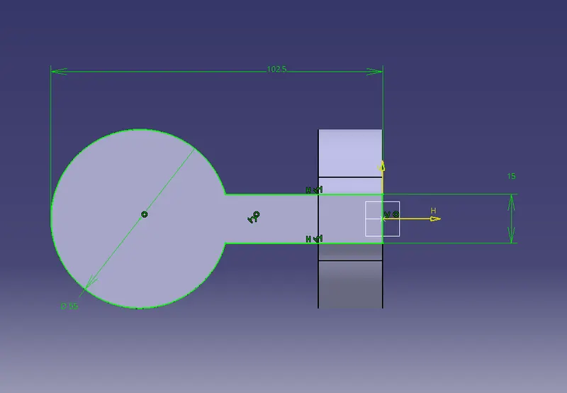
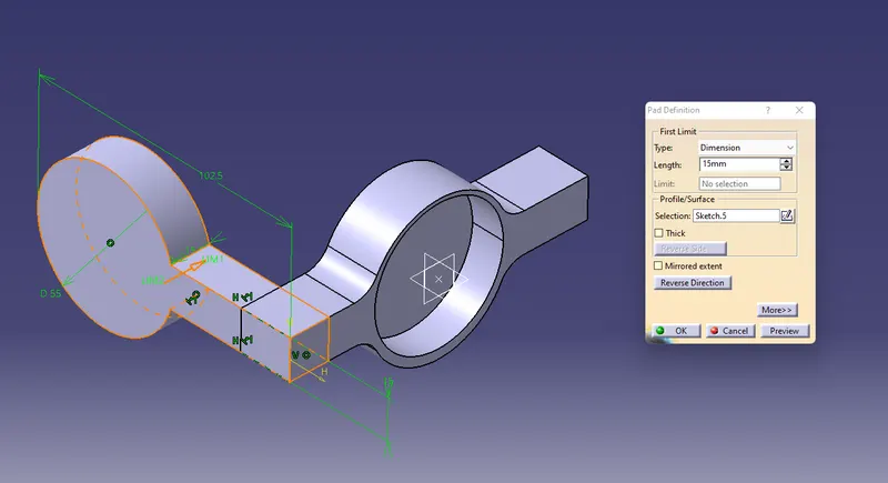
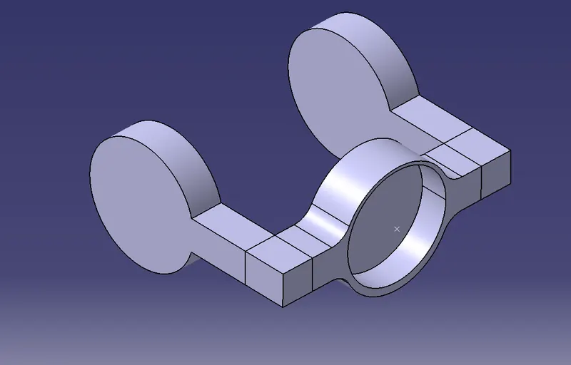
Create 50mm dia circle pad it then use remove operation
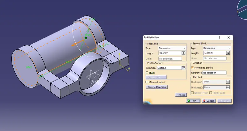
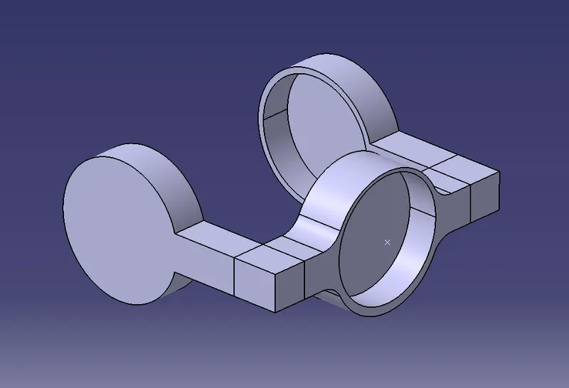
then use add command
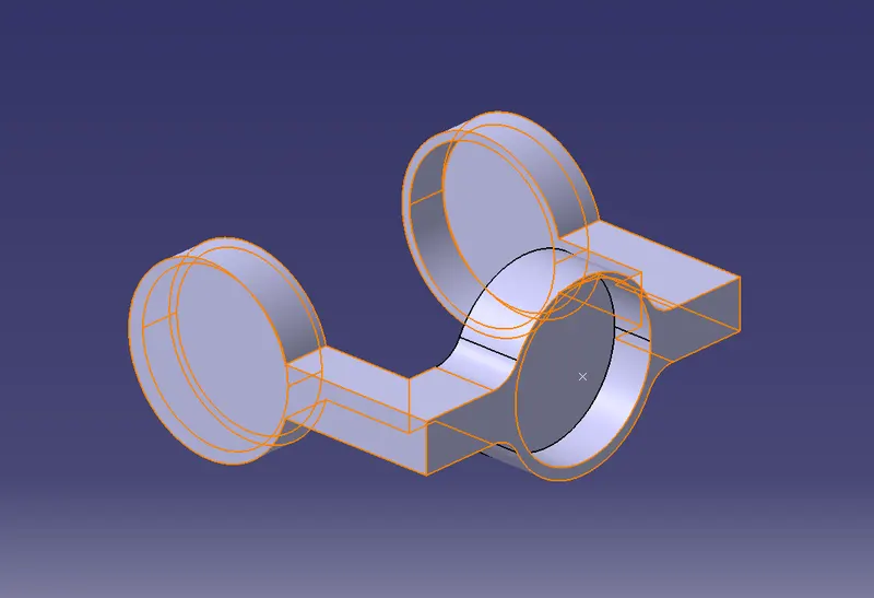
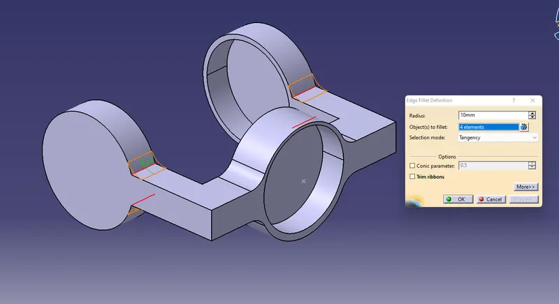
Give 10mm edge fillet
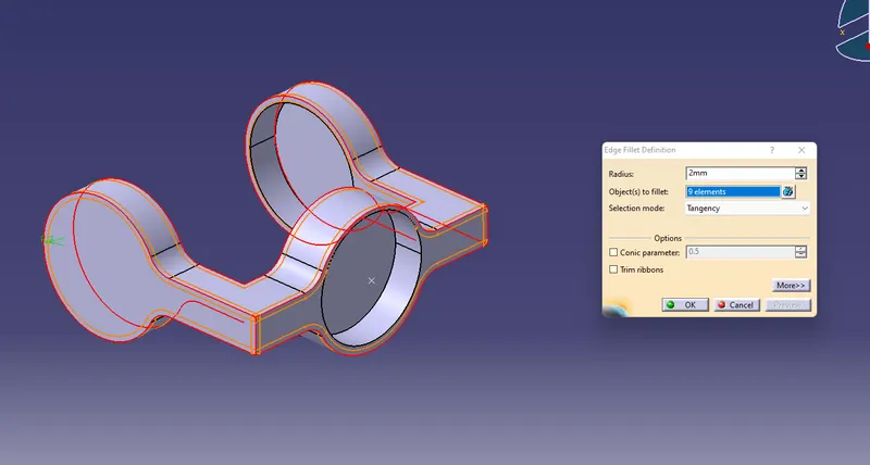
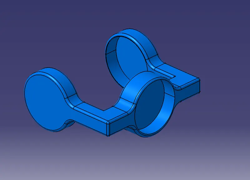
2mm fillet to corners of our handle
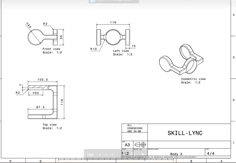
Now its time to assemble all the CV joint Parts together
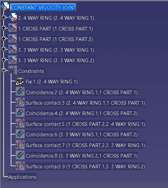
First fix the 4 WAY locator handle
Then use coincidence between 4 way handle and Cross point
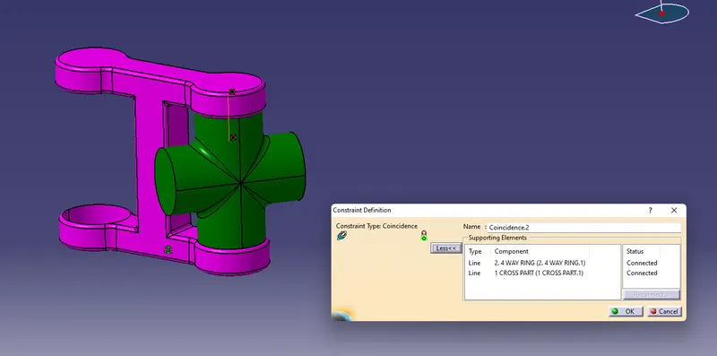
and create surface contact between faces of both joints
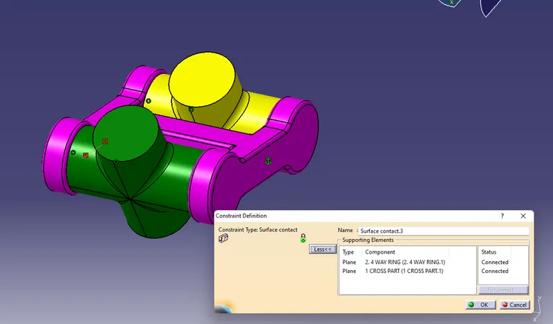
Just like that add copy of cross joint and use coincidence
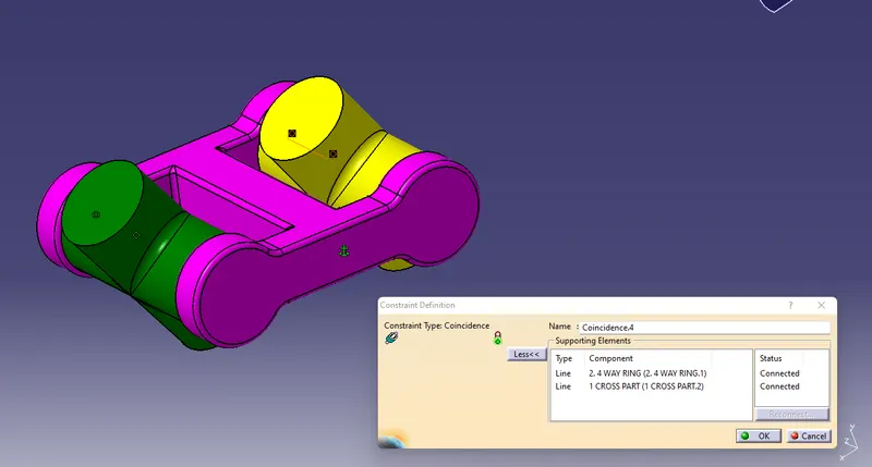
and create surface contact between faces of both joints
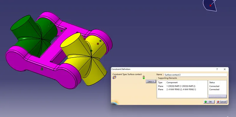
then insert 3 Way handle and use coincidence between handle and cross joint and then use surface contact between surfaces of both joints and do same copy for another 3 way handle
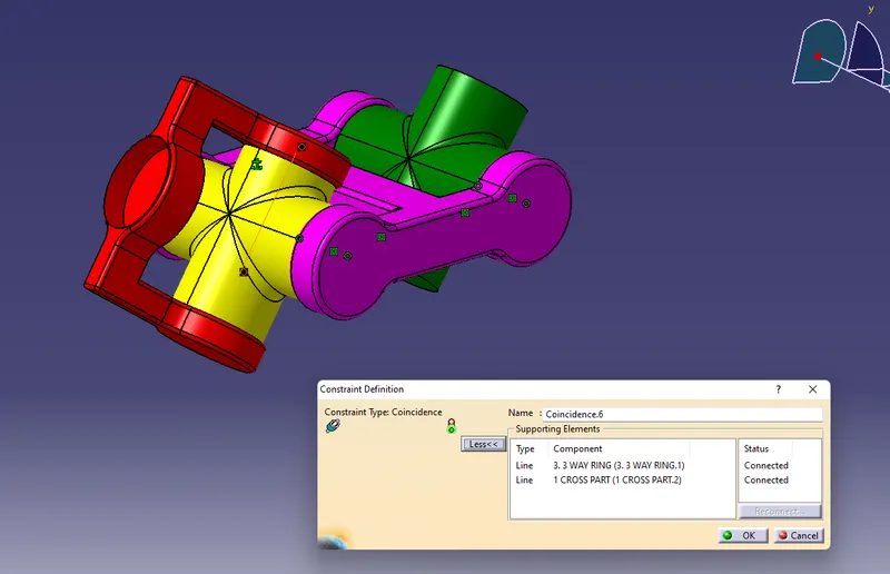
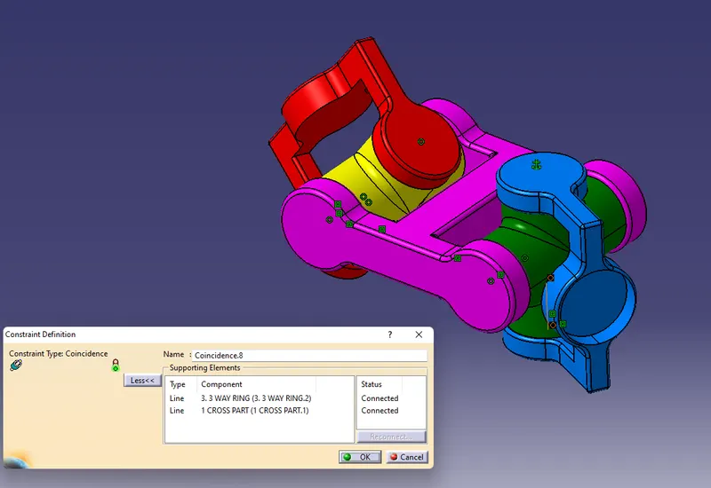
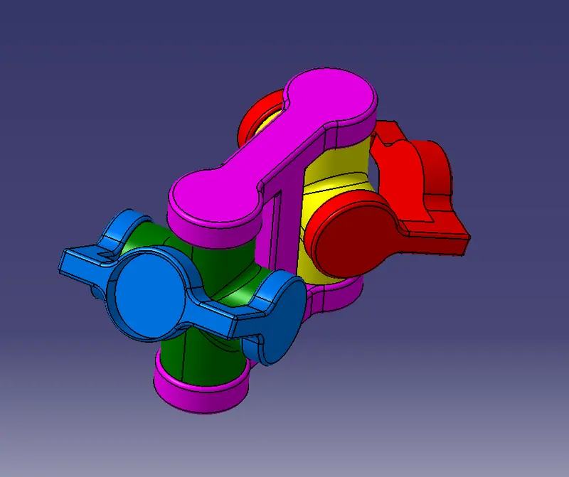
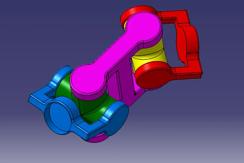
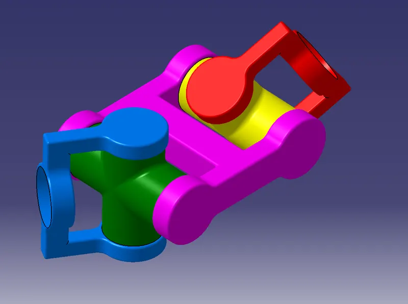
Complete Assembly of Constant Velocity Joint
.