Week 9 - Project - Master Section Development
Project - Master Section Development
Aim: Master Section Development
Pillars In Cars
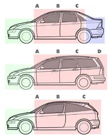
Pillars are the vertical or nearly vertical supports of a car's window area or greenhouse—designated respectively as the A, B, C, or (in larger cars) D-pillar, moving from front to rear, in profile view.
The consistent alphabetical designation of a car's pillars provides a common reference for design discussion and critical communication. As an example, rescue teams employ pillar nomenclature to facilitate communication when cutting wrecked vehicles, as when using the jaws of life.
Design
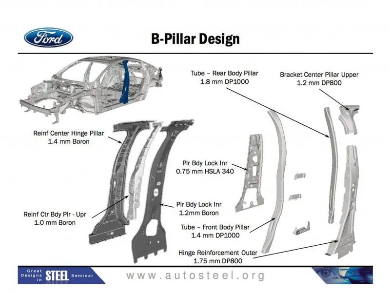
In the case of the B (or center) pillar on four-door sedans, the pillar is typically a closed steel structure welded at the bottom to the car's rocker panel and floorpan, as well as on the top to the roof rail or panel. This pillar provides structural support for the vehicle's roof panel and is designed for latching the front door and mounting the hinges for the rear doors.
As the most costly body components to develop or re-tool, a vehicle's roof and door design are a major factor in meeting safety and crash standards. Some designs employ slimmer, chamfered windscreen pillars, A-pillars, to help improve driver vision (thus reducing blind spots) through the use of stronger alloy steel in these components. As "perhaps the most complex of all the structures on the vehicle", the center or B-pillar may be a multi-layered assembly of various lengths and strengths.
Closed vehicles without a B-pillar are widely called hardtops and have been available in two or four-door body styles, in sedans, coupes, and wagons. Designs without a center or "B" pillar for roof support behind the front doors offer increased occupant visibility, while in turn requiring underbody strengthening to maintain structural rigidity. In the early 1970s, General Motors broadened their definition of "hardtop" to include models with a B-pillar although: "up to then, everybody thought a hardtop was a car without a center pillar.
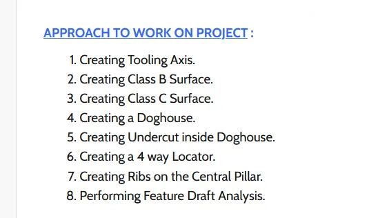
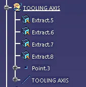
1. Creation of Tooling Axis
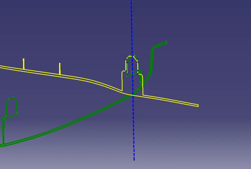
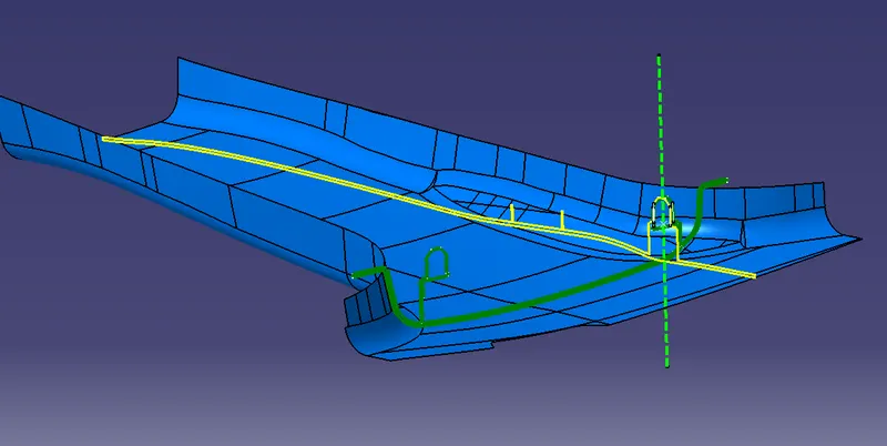
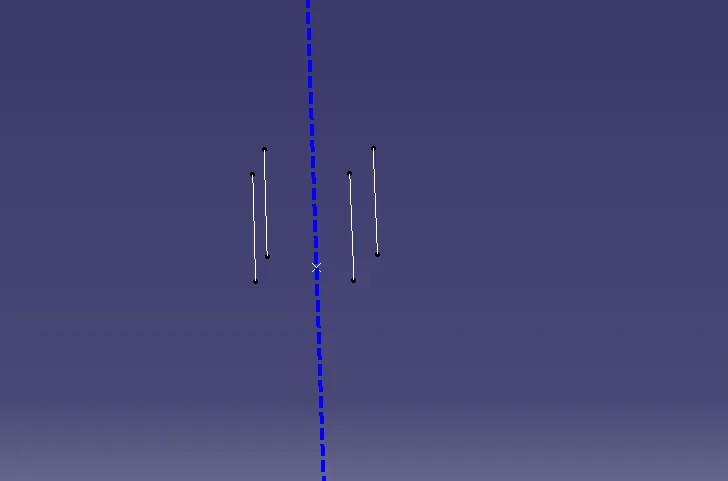
2: Procedure for creating B Surface
1. Offset the Surface about 2mm
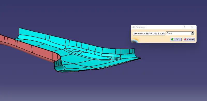
Create a plane using three points on mastersection
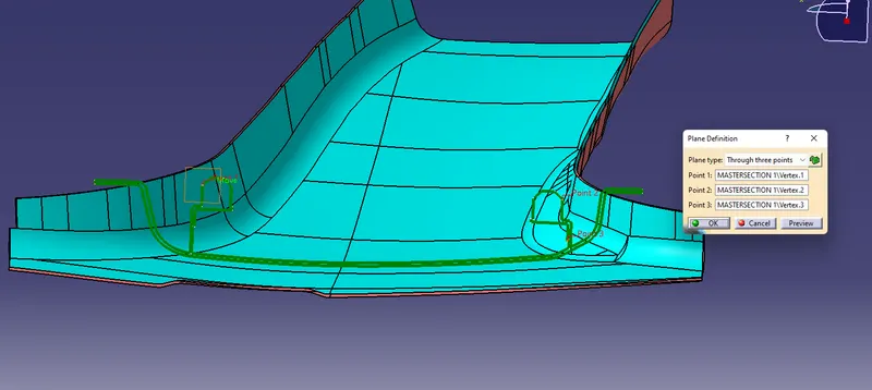
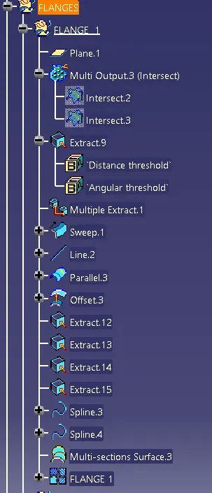
Tangentially extract the boundary using multiple extracts
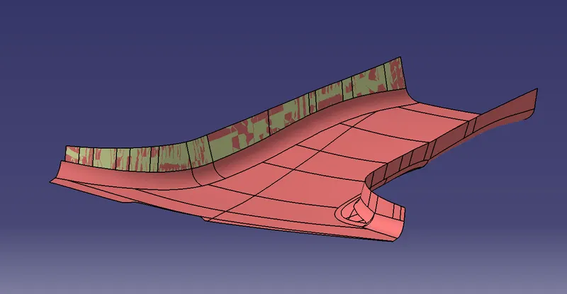
Create flange and trim with class a surface
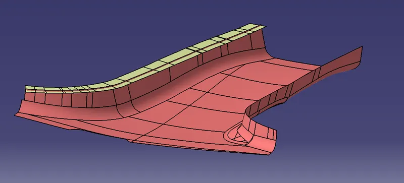
Create Flange 1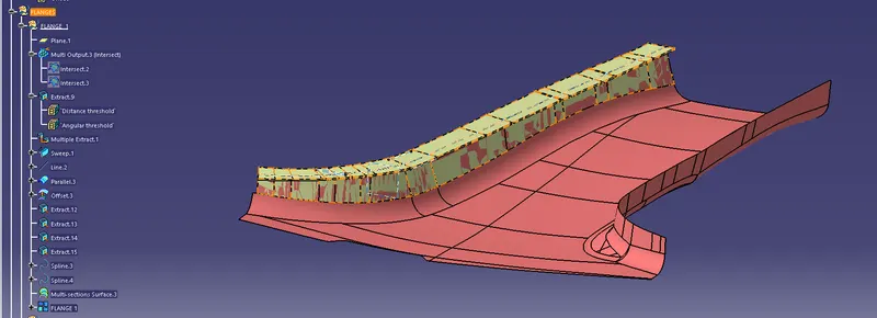
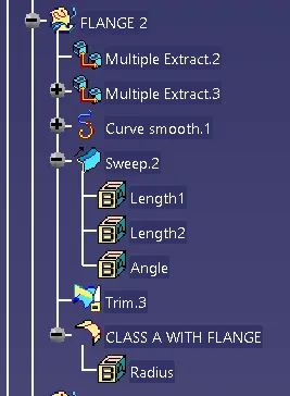
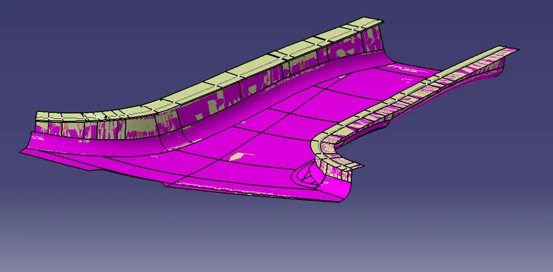
Trim the flange with class A surface
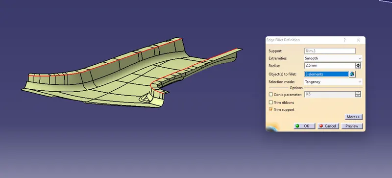
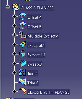
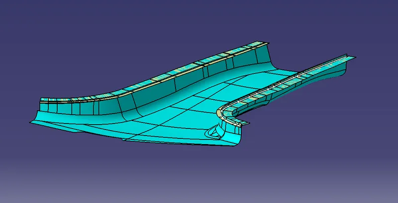
Create the Same flange on B Surface
Procedure for creating C Surface
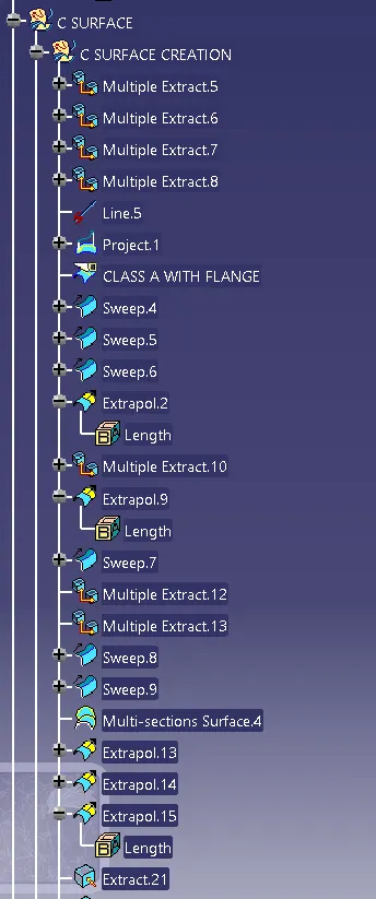
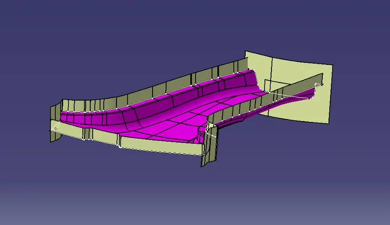
for creating the side face make sure sweep angle should be outside
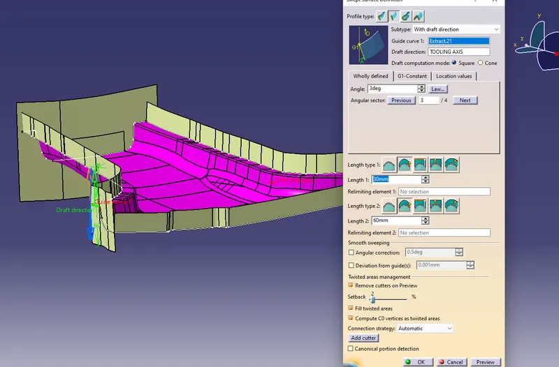
Now its time to trim this with Both Class A And B for Class C Creation
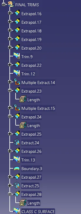
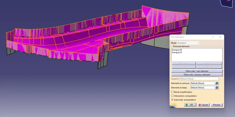
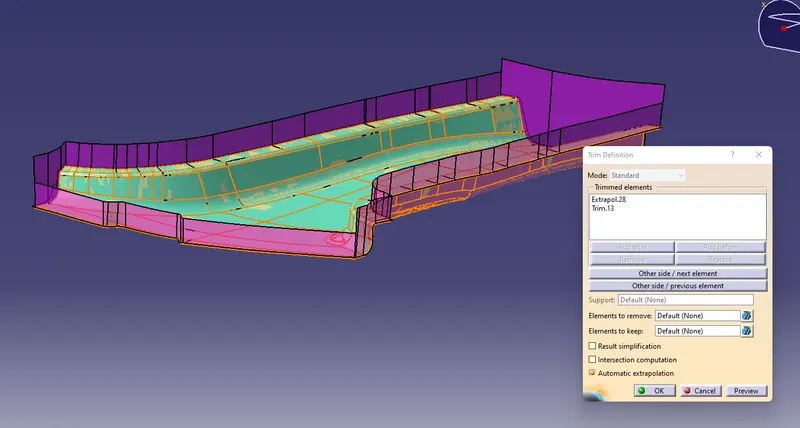
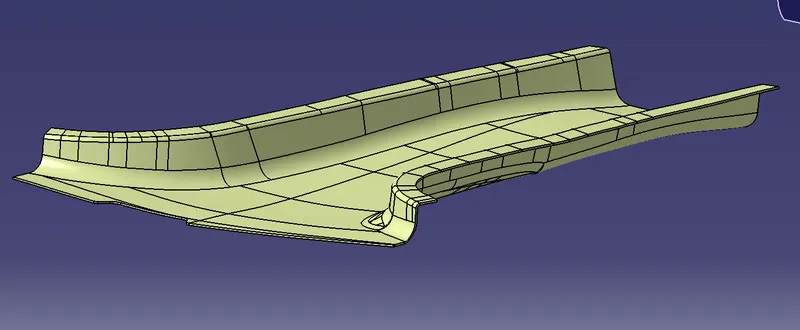
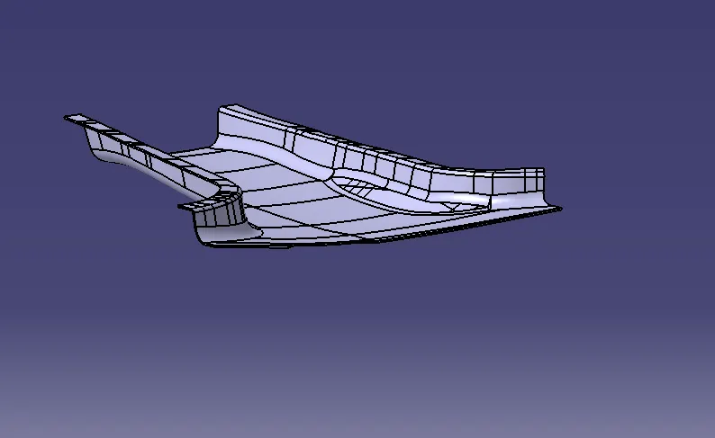
Creation of Dog House and 4 Way Locator
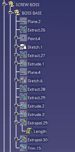
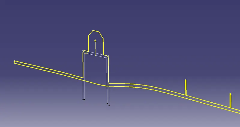
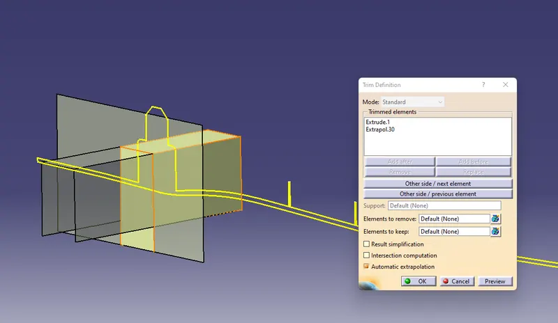
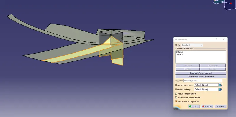
creation of 4 Way locator
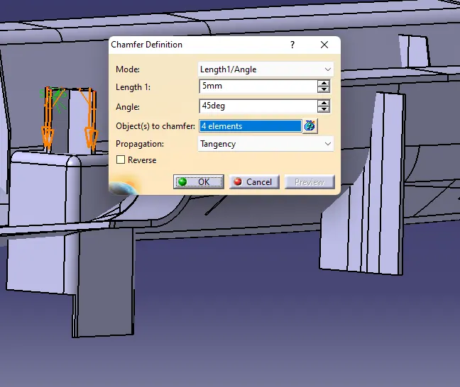
provide chamfer of 5mm to 45deg
and a draft of 0.5 deg
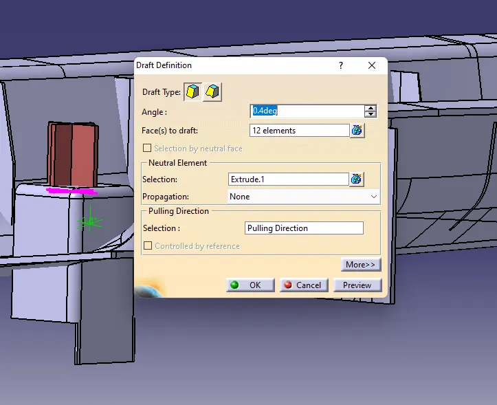
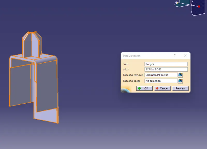
After creating Dog House and Locator one Side make asymmetry on another side on the master section
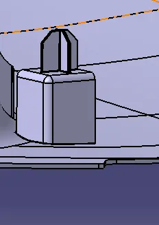
Creation of Ribs
Draw the sketch of rib with 50mm distance between each ribs
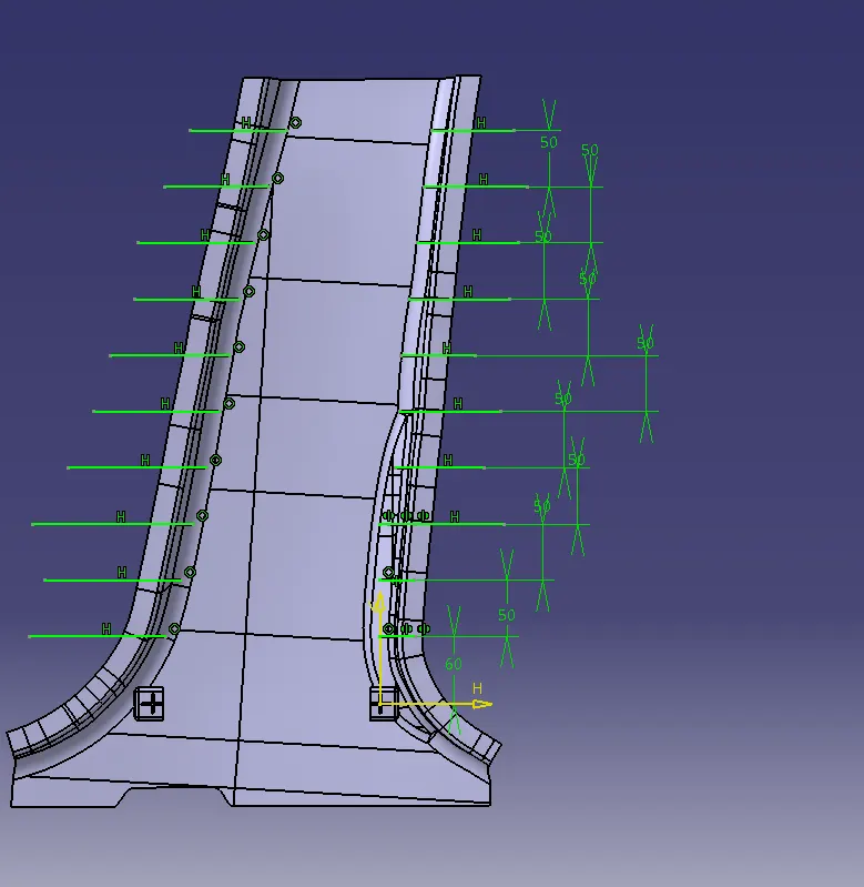
extract the all individual line from sketch
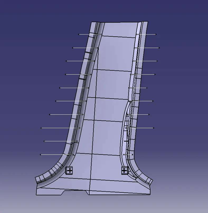
Extrude all ribs
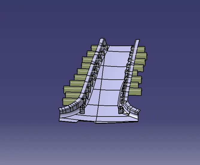
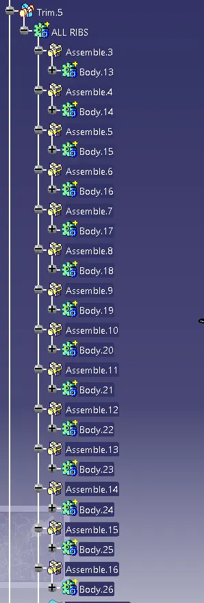
Thicken all ribs one by one
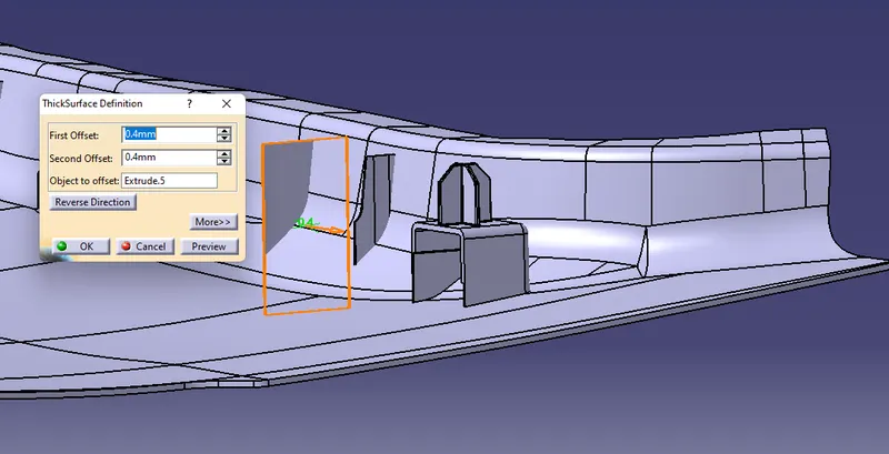
provide a draft angle of 0.5 deg
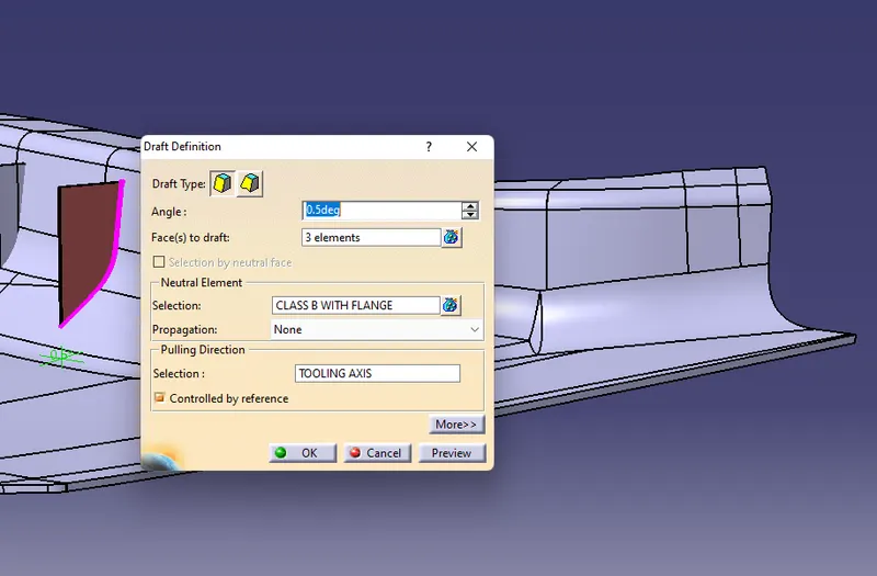
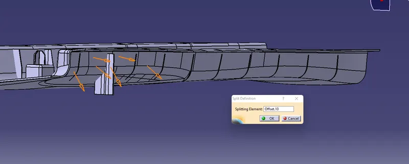
Split all the Ribs with offset surface
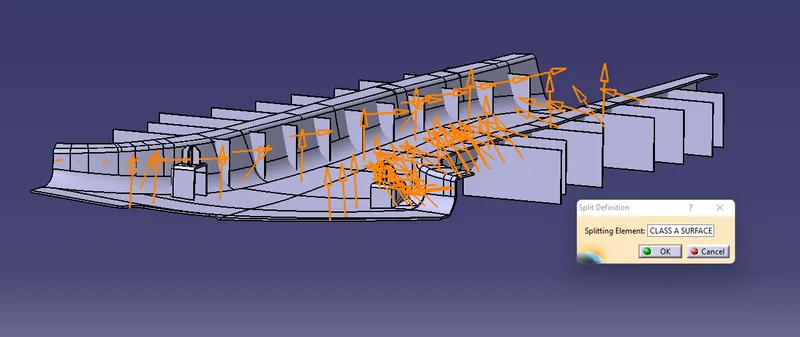
Split all ribs with class A surface
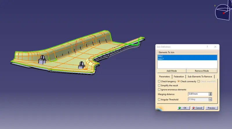
Trim all ribs with offset surface
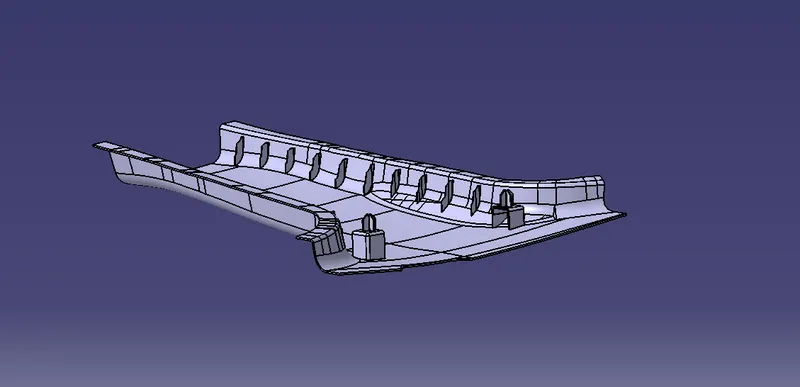
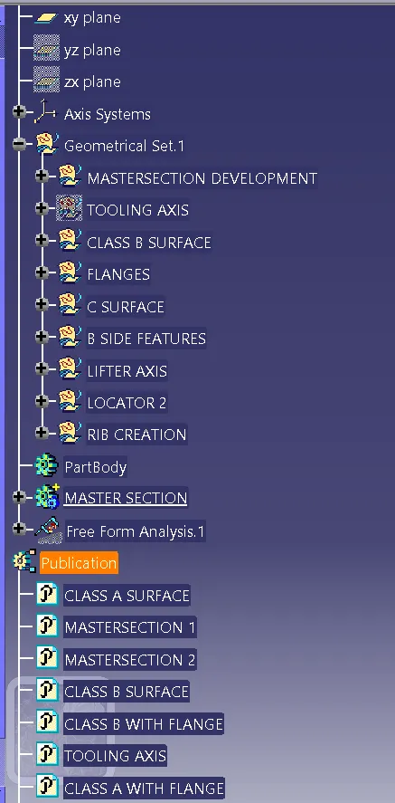
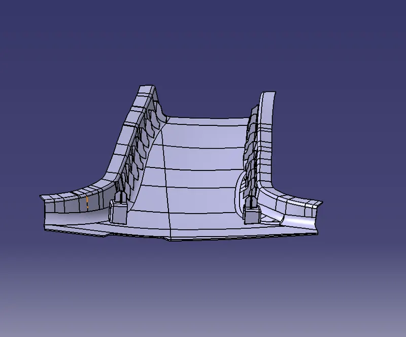
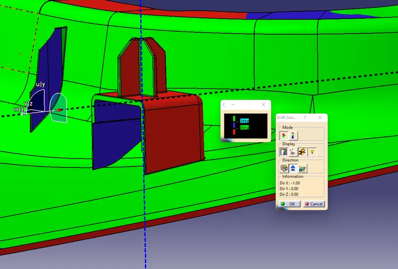
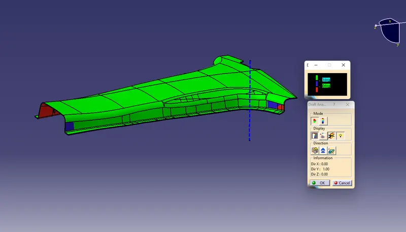
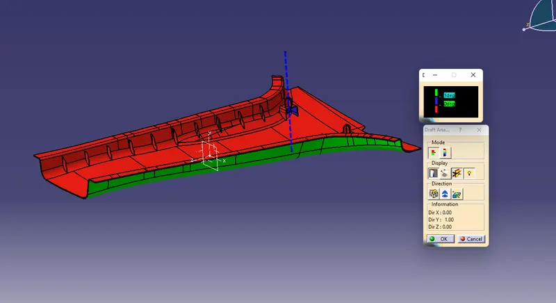
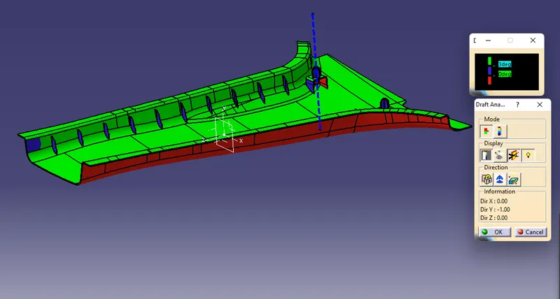
Draft Analysis
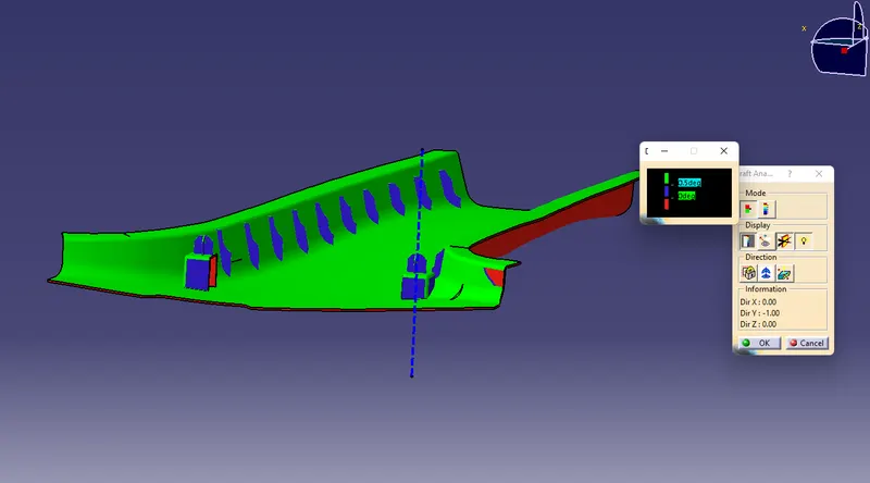
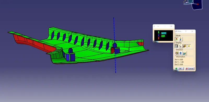
Draft Analysis on Dog House and 4 Way Locator
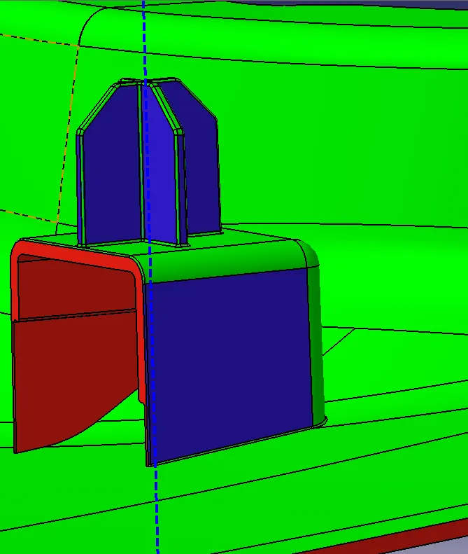
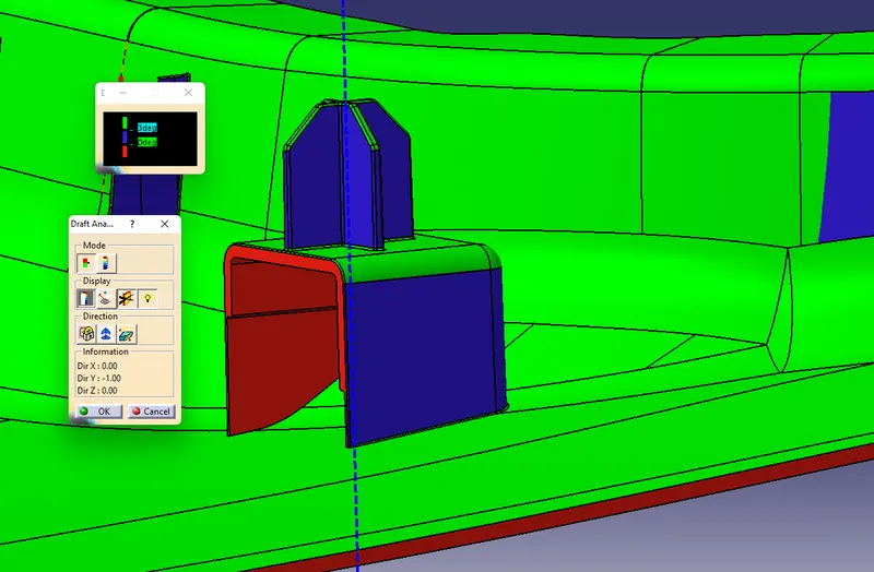
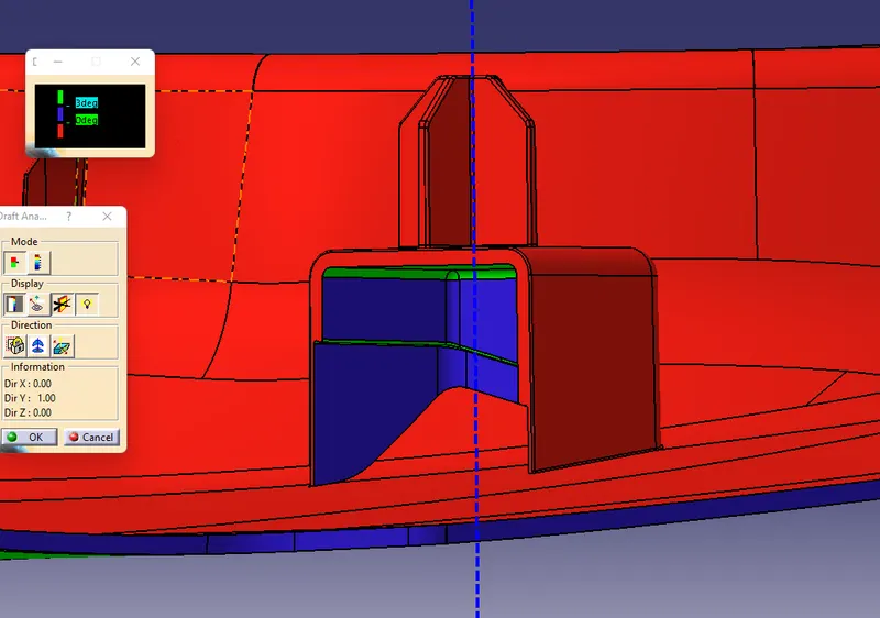
draft Analysis on Dog house using Lifter Axis