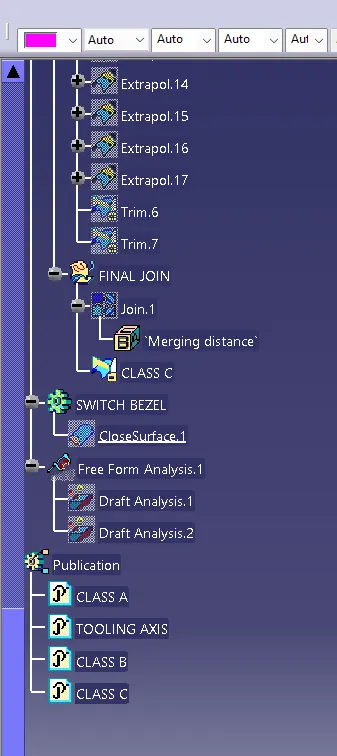
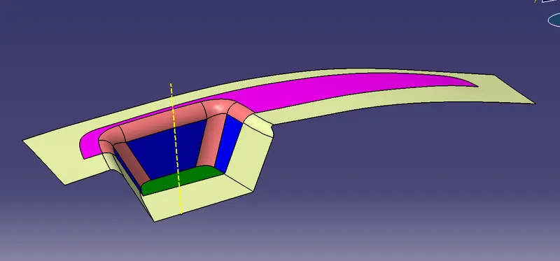
Week 8 - Challenge 3 - Switch Bezel Design
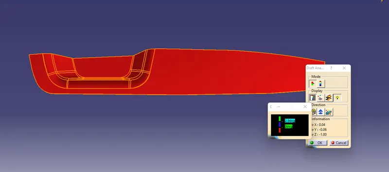
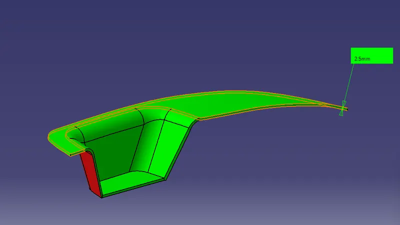
Draft Analysis
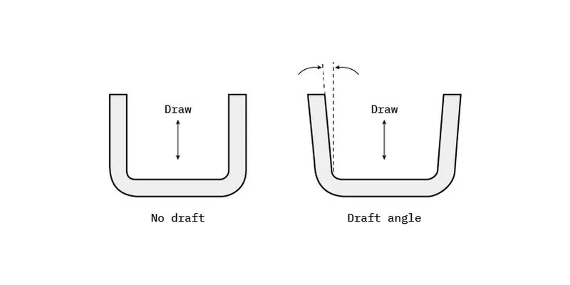
In engineering, the draft is the amount of taper for molded or cast parts perpendicular to the parting line. It can be measured in degrees or mm/mm (in/in).
Consider the fabrication of a hollow plastic box, without a lid. Once the plastic has hardened around the mold, the mold must be removed. As the plastic hardens, it may contract slightly. By tapering the sides of the mold by an appropriate "draft angle", for instance, 2° (two degrees), the mold will be easier to remove. This is a practice that is used, in applicable cases, when working with fiberglass.
PERFORMING A DRAFT ANALYSIS
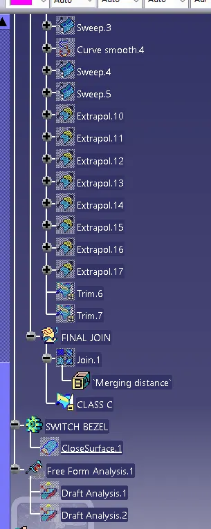
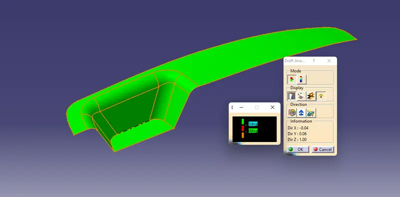
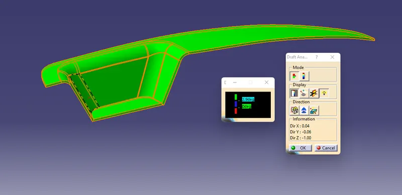
The Draft Analysis command enables you to detect if the part you drafted will be easily removed.
- This type of analysis is performed based on color ranges identifying zones on the analyzed element where the deviation from the draft direction at any point, corresponds to specified values.
These values are expressed in the unit as specified in Tools > Options > General > Parameters > Unit tab.
You can modify them by clicking on their corresponding arrow or by entering a value directly in the field. - The mapping texture accuracy depends on the video card used. Therefore, colors displayed on surfaces could be wrong according to the color scale, when the value displayed on the fly is right because the analysis is recomputed at the cursor location.
Sometimes, in the case of extremely closed values, it is recommended to switch to the Quick mode to improve the color display accuracy. - The maximal draft analysis accuracy is 0.01 deg. According to the graphic card performance, this accuracy can be debated.
- The different mapping analyses of the same surfaces cannot be displayed simultaneously, even if you have set the mapping analyzes in no show. You need to visualize them one after the other.
TOOLING AXIS CREATION
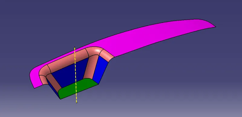
The tooling axis is created towards the core side of the mold which is analyzed visually for the best possible tooling axis.
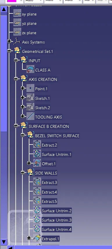
- Before creating the tooling axis at CG dummy axis is created using the point and direct command.
- Using intersection, lines contact with the walls, the line bisecting the two lines passing through the point will be the tooling axis.