Hood design-Week 2
Hood Design
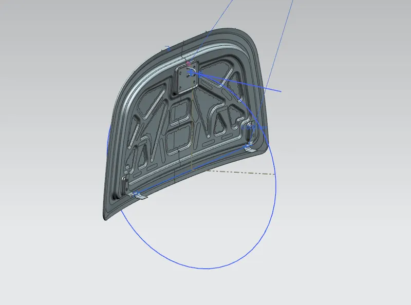
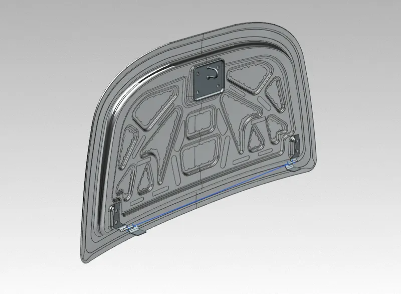
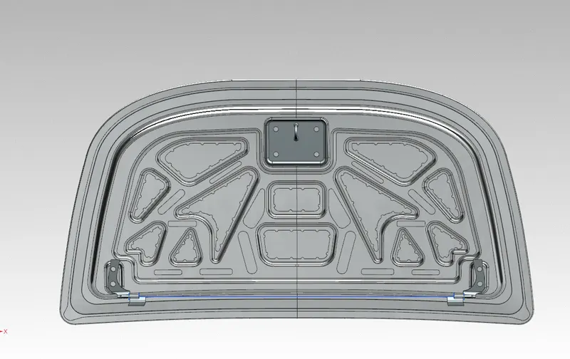
Aim: Design the Hood outer panel, inner panel, and the necessary reinforcements by following the Master section mentioned with the design parameter explained in the videos. Submit an assembly of the Hood inner panel, outer panel, latch, hinge, and reinforcements.
The hood (North American English) or bonnet (Commonwealth English) is the hinged cover over the engine of motor vehicles. Hoods can open to allow access to the engine compartment or trunk (boot in Commonwealth English) on rear-engine and some mid-engine vehicles) for maintenance and repair.
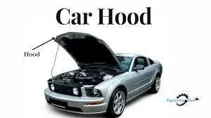
Styles and materials
On front-engined cars, the hood may be hinged at either the front or the rear edge, or in earlier models (e.g. the Ford Model T) it may be split into two sections, one on each side, each hinged along the centerline.
Hoods are typically made out of the same material as the rest of the bodywork. This may include steel, aluminum, fiberglass, or carbon fiber. However, some aftermarket companies produce replacements for steel hoods in fiberglass or carbon fiber to make the vehicle lighter.
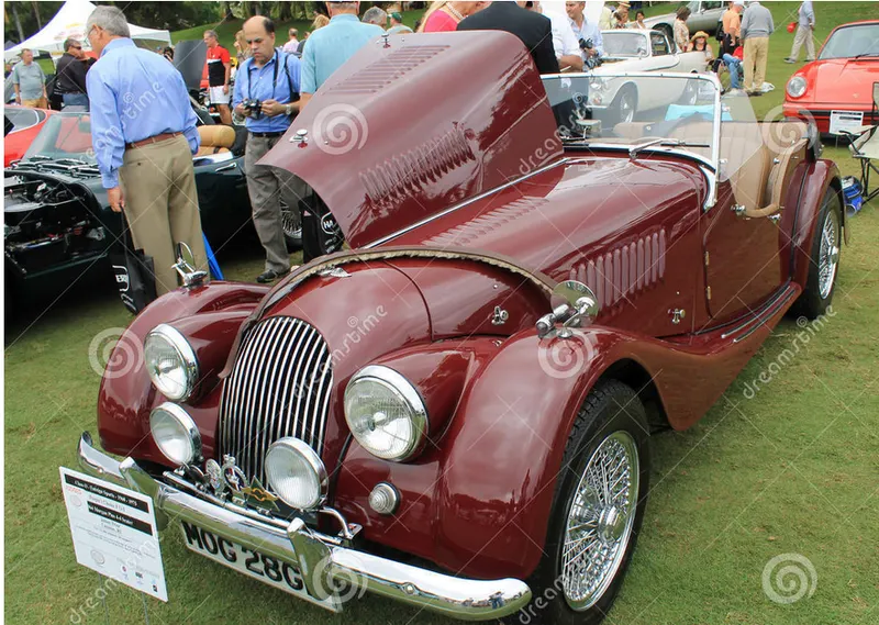
A further variant combines the bonnet and wheel arches into one section and allows the entire front bodywork to tilt forwards around a pivot near the front of the vehicle (e.g. that of the Triumph Herald).
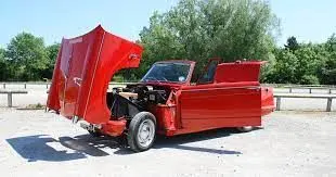
ENGINE HOOD: Hood which is also called ENCON, serves as an access panel to ENGINE COMPARTMENT of an automobile. It is an assembly made of OUTER and INNER PANELS to meet various safety & design requirements. Following are the design considerations involved to design hood,
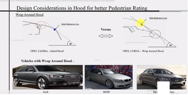
1. PEDESTRIAN SAFETY.
2. VEHICLE QUALITY.
3. OCCUPANT SAFETY.
4. STYLING.
5. MANUFACTURABILITY.
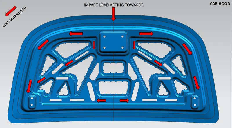
1. PEDESTRIAN SAFETY: Pedestrian safety is always a factor involved in the design of the hood. This is achieved by proper selection of material that can readily deform avoiding risk during impact, providing emboss to inner panels, etc. This is one of the major factors for a vehicle to have better safety ratings.
2. VEHICLE QUALITY: This involves how best the hood can be designed to have better quality in terms of torsional stiffness, dentb resistance (Hailstone and stone chippings), corrosion resistance, better weight distribution, and noise attenuation.
3. OCCUPANT SAFETY: The design consideration must include the impact caused due to FRONTAL CRASH COLLAPSE. Under such a scenario it is expected that the HOOD maintains its integrity with hinges and also retains any of the loosed components from engine compartments.
4. STYLING: Better surface quality (A-class surface finishing), Tight radii on hemmed panel edges & low strain between curved regions of the inner and outer panel.
5. MANUFACTURABILITY: The design should be always considered for Manufacturability e.g. embossing on the inner panel should have sufficient draft angles provided for the punching tool to flow in and flow out.
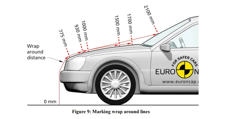
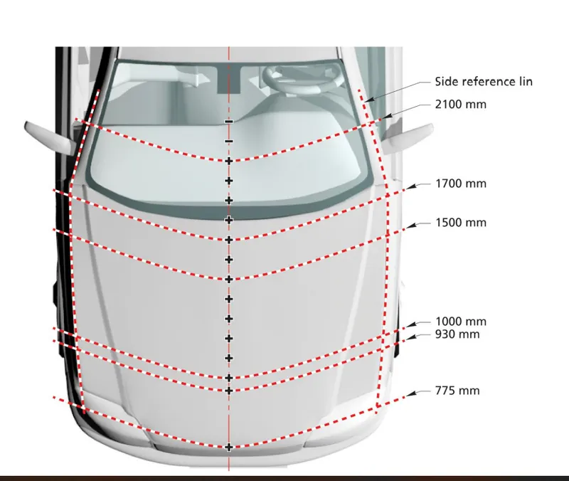
- Marking Wrap Around Distances
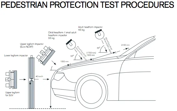
The headform test area is defined as the outer structure that includes the upper surface of all outer
structures. It includes, but is not limited to, the bonnet, wings, windscreen scuttle, wiper
arms/spindles, windscreen frame, A-pillars, and roof. It is bounded by the geometric trace of the
1000mm wrap-around line in the front, the Bonnet Side Reference Lines, and the 2100mm wrap-around distance (WAD).
- Begin at the vehicle centreline.
Place the end of a flexible tape measure or graduated wire on the floor vertically below the front face of the bumper. - Wrap the tape or wire over the bumper, bonnet windscreen, and roof ensuring that it is maintained in a vertical longitudinal (X, Z) plane and that its end is still in contact with the ground.
- The tape should be held taut throughout the operation, vertically below the front face
of the bumper, see Figure - Mark on the bumper/grille, bonnet top, windscreen, A-pillars, and/or roof the wrap-around distances of 775mm, 930mm, 1000mm, 1500mm, 1700mm, and 2100mm. These are the geometric traces described on the outer surface of the vehicle by the end of the flexible tape or wire 775mm, 930mm, 1000mm, 1500mm, 1700mm, or 2100mm long, when it is held in a vertical fore/aft plane of the car and traversed across the front of the bonnet and bumper.
Impact-absorption bonnet and bumpers
Mazda uses various methods to reduce injury to pedestrians in the event of a collision.
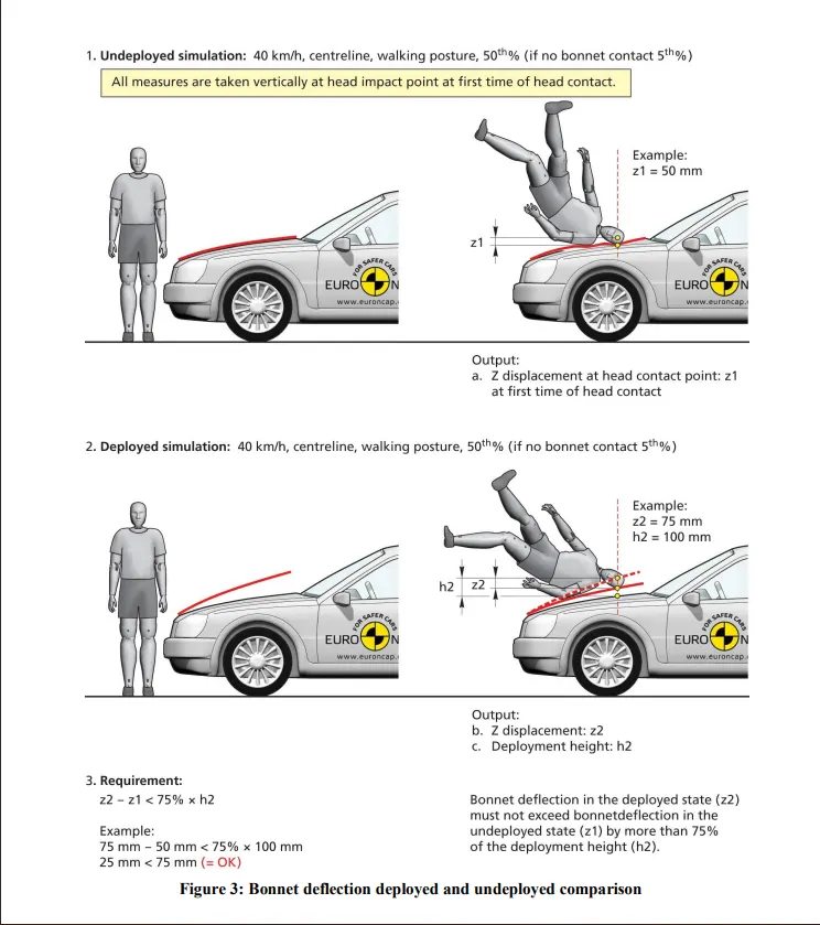
The Impact Absorption Bonnet mitigates the impact to a pedestrian's head in a pedestrian accident.
Active Bonnet is designed to mitigate the shock to the head in the event the vehicle collides with a pedestrian. Designed to activate with a defined speed range, the system causes the rear end of the bonnet to pop up when an impact exceeding a certain threshold is detected, creating a shock-absorbing space between the bonnet and the engine.
Energy absorption materials are used in the front part of the vehicle which hits pedestrians' knees to mitigate the severity of pedestrian's knee injuries. Also, stiffening reinforcement is placed at the bottom of the bumper to better prevent pedestrian's legs from going under the vehicle. In anticipation of an accident, the shape of the bonnet is carefully designed to reduce the damage to the pedestrians' knees, which are an important part of the body for walking.
How Active Bonnet works
Bonnet Side Reference Line
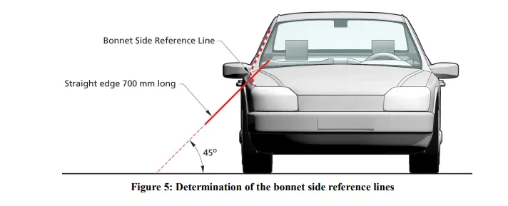
The Bonnet Side Reference Line is defined as the geometric trace of the highest points of contact between a straight edge 700mm long and the side of a bonnet, as defined in Section 3.3.1 and A-Pillar, when the straight edge, held parallel to the lateral vertical plane of the car and inclined inwards by 45is traversed down the side of the bonnet top and A-Pillar, while remaining in contact with the surface of the body shell, any contact with door mirrors is ignored. See Figure 5. Where multiple or continuous contacts occur the most outboard contact shall form the bonnet side reference line.
Figure: Determination of the bonnet side reference lines
Fix a straight edge that is 700mm long at 45 to the vertical. With this edge in a plane parallel to the lateral vertical plane of the car, position the straight edge at the front of the front wing and in contact with, the bonnet.
- Mark the uppermost point of contact of the straight edge and wing.
- Pull the straight edge away from the wing, move it towards the other end of the vehicle by
not more than 100mm, and then back into contact with the wing. - Mark the uppermost point of contact of the straight edge and wing
Data to be used:
Hood Thickness Information
- Outer Panel Thickness = 0.75mm
- Inner Panel Thickness = 0.75mm
- Reinforcement Thickness = 1.5mm
Master sketch:
- Embossing:
The metal sheet embossing operation is commonly accomplished with a combination of heat and pressure on the sheet metal, depending on what type of embossing is required. Theoretically, with any of these procedures, the metal thickness is changed in its composition.
The metal sheet is drawn through the male and female roller dies, producing a pattern or design on the metal sheet. Depending on the roller dies used, different patterns can be produced on the metal sheet. The pressure and a combination of heat actually "irons" while raising the level of the image higher than the substrate to make it smooth. The term "impressing" refers to an image lowered into the surface of a material, in distinction to an image raised out of the surface of a material.
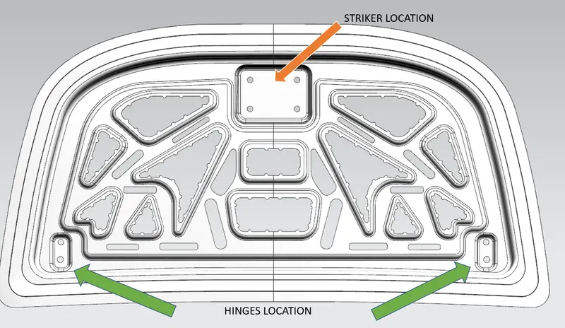
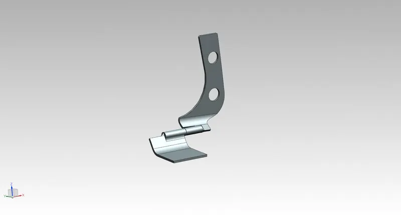
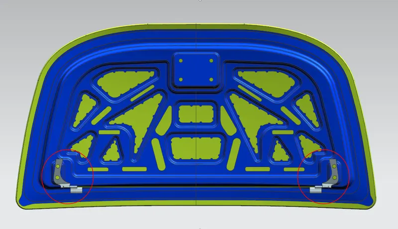
Hinges are used to join two parts together while allowing them to rotate relative to each other. They typically have two flat faces, known as leaves. One leaf is attached to each of the parts being joined.
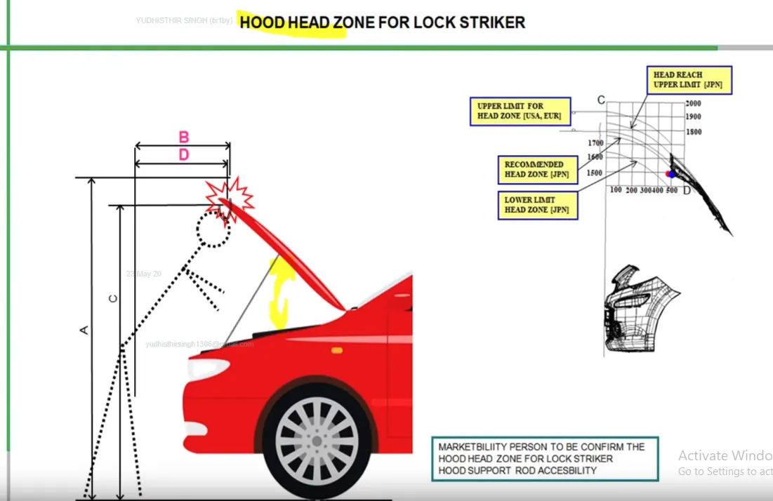
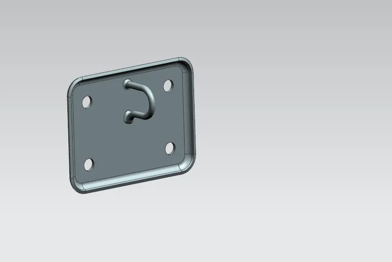
Hood striker It bolts to the underside of the hood at the front. It engages the hood latch when closed.
For the term hood striker may also exist other definitions and meanings, the meaning and definition indicated above are indicative not be used for medical and legal or special purposes.
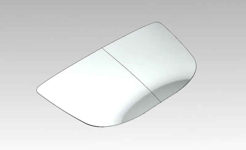
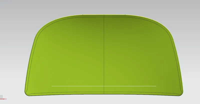
External Skin or Outer Panel of Car Hood to cover the Engine and Protect the Engine as well as Aesthetic of a car
Hemming
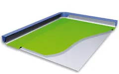
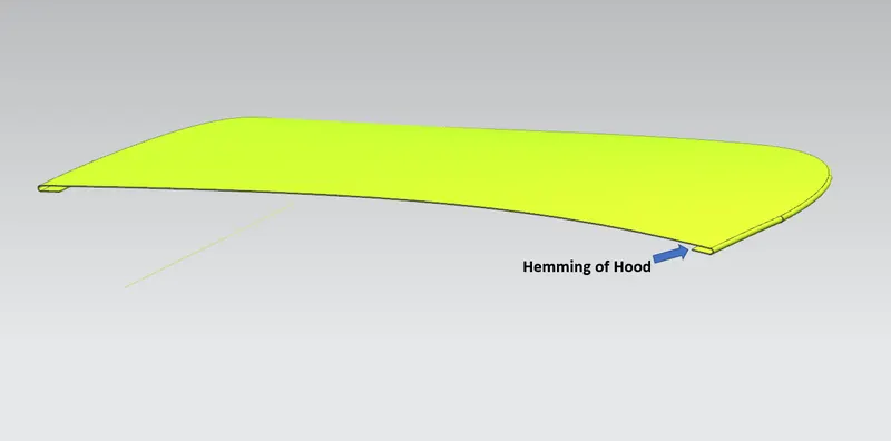
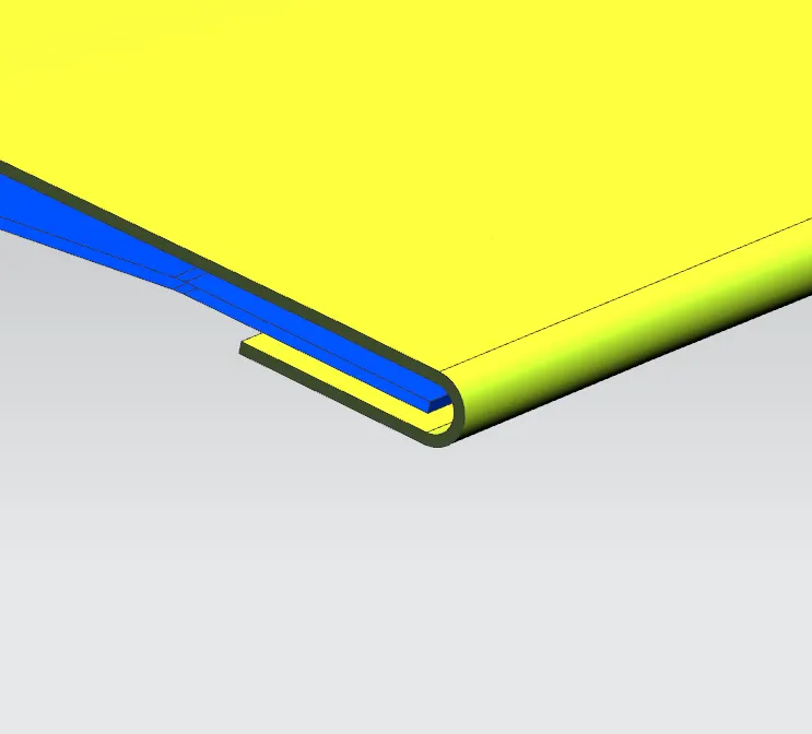
Hemming is a forming operation in which the edges of the sheet are folded or folded over another part in order to achieve a tight fit. Normally hemming operations are used to connect parts together, to improve the appearance of a part and to reinforce part edges.
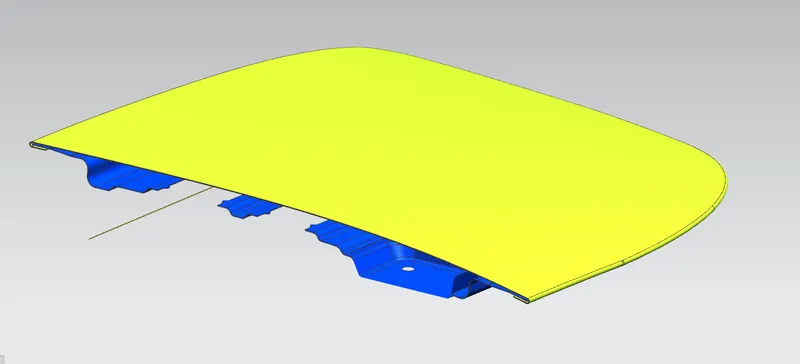
In car part production, hemming is used in assembly as a secondary operation after deep drawing, trimming and flanging operations to join two sheet metal parts (outer and inner) together. Typical parts for this type of assembly are hoods, doors, trunk lids and fenders.
The accuracy of the hemming operation is very important since it affects the appearance of the surface and surface quality. Material deformations, which occur during the hemming process, can lead to dimensional variations and other defects in parts. Typical hemming defects are splits or wrinkles in the flange, material overlaps in the corner areas or material roll-in. This is why it is important to use simulation tools in order to, on the one hand, better understand the hemming process and, on the other hand, significantly reduce the number of “trial and error” loops during tryout und production.
There are various types of hemming operations:
- Conventional die hemming
- Roll hemming
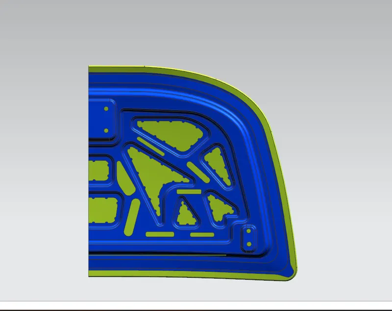
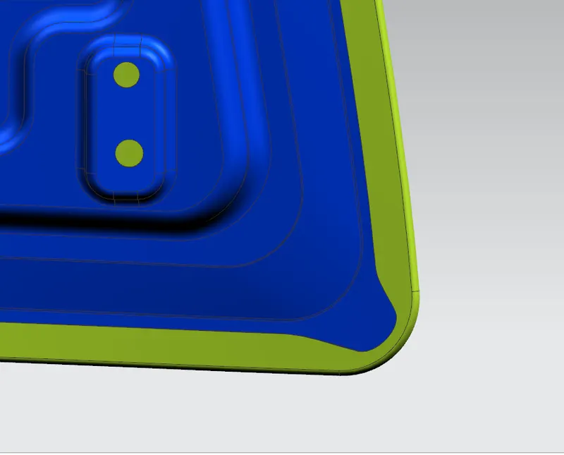
Body Sealer
-
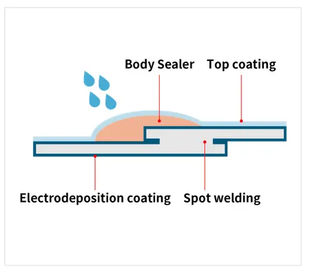
Body sealers that provide manufacturers with truly waterproof, dustproof, and corrosion‐proof solutions for automotive body joints that are susceptible to environmental threats. These one‐component PVC sol/acryl sol sealing materials accommodate multiple wet-on-wet coating applications without requiring the time and expense of oven curing between coats. These sealers are tough on the elements, yet easy on your team—and your bottom line.
Distinct Benefits
- Protection at its best. Body Sealer keeps dust and moisture out, preserving the integrity of steel panels inside and outside of the automobile cabin. It puts a durable, rustproof coating on vulnerable steel plate edges, virtually eliminating corrosion.
- Ultimate application flexibility. Body Sealer can be applied manually or robotically during the paint process, then cured in the paint shop’s baking oven.
- Excellent adhesion. Our body sealer is engineered to provide exceptional adhesion, including bonding securely to electrodeposition coatings.
- Tailored to your needs. Sunstar’s flexible design allows for the material’s properties and performance characteristics to be optimized for each working environment, application, coating, and working condition. Custom specifications can be set to further fine‐tune coating properties and assure exceptional paint finishing for your shop.
- Excellent compatibility. Our Body Sealer systems are highly compatible with virtually all adherents and paints and are cured in conventional OEM paint shop baking ovens one time (no need for curing between each applied coating). Achieving excellent results is easy when everything works together.
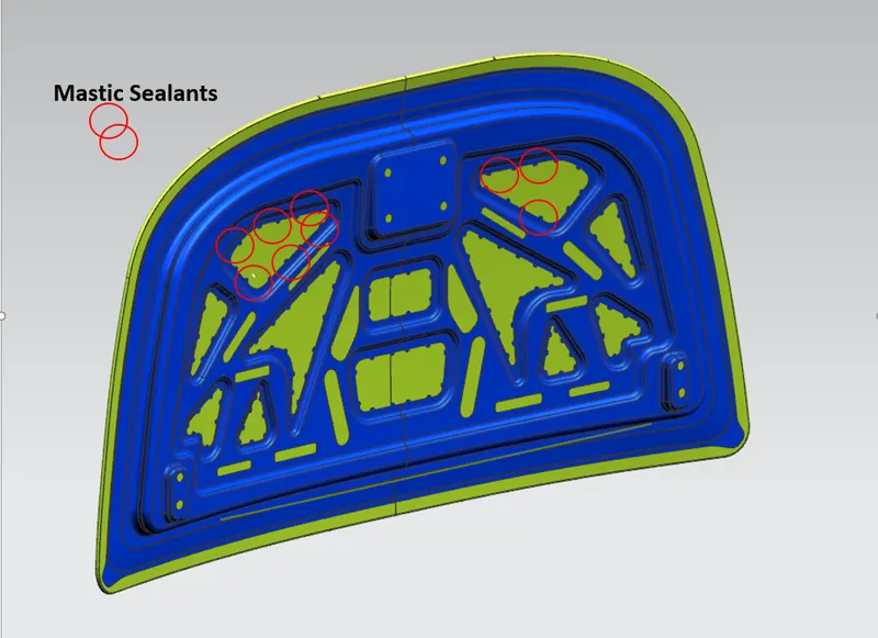
Mastic Adhesive
Sunstar’s mastic adhesive was developed specifically to bond exterior automotive panels to the vehicle’s inner panel structure, such as on roofs, doors, and hoods. This one‐component synthetic rubber sealer remains elastic after curing to reduce panel flapping and to prevent panel distortion
Distinct Benefits
- Great application flexibility. With minimal stringing effect, our mastic adhesive provides controlled application for consistent performance during robotic application. The easy-to-handle formula can also be applied with a handgun or pump.
- Excellent adhesion to oily steel plates. Mastic adhesive can be applied directly to oily steel plates without pre‐treating the metal, creating a strong and permanent bond.
- Ideal for aluminum panel bonding. Our mastic adhesive is suitable for a variety of metals and is an excellent choice for assemblies where aluminum and other alloys are used.
- A formulation for virtually every need. Mastic adhesive is available in a range of hardness and foam expansion ratios to provide optimal performance for each application.
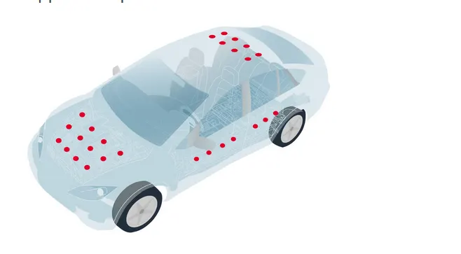
Location of Mastics on Hood
Position of Hinges
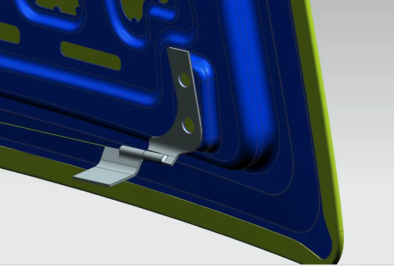
Positioning Striker and Hinges using Proper geometry and angle