Week 9 - Project 1 - Door Applique Design with Engineering Features
Door Applique Design with Engineering Features
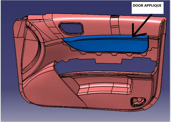
Heat Staking
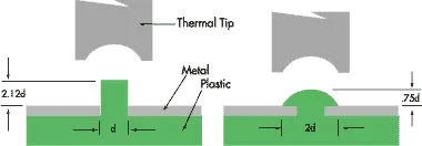
Heat Staking is a pulsed-heat process to join two or more parts out of which one at least is made of plastic. The process is to deform the plastic material using heat and force at a set process time. The bond is made by partially de-forming the plastic part in order to fix the other.
Heat Staking makes it easy to bond metal to plastic and is commonly used in high volumes/low-cost applications such as automotive, IT, and consumer appliances.
Heat Staking Benefits:
- Similar and dissimilar materials may be joined: metal to metal, plastic to plastic, metal to plastic
- Accurate control operating within a small process window
- Local heating resulting in no damage to surrounding materials
- Processing of glass-filled materials
- No mechanical vibration
- Many heat-stake shapes are possible through custom-designed tools
Locating & Clamping Principles
Locating and clamping are the critical functions of any work holder. As such, the fundamental principles of locating and clamping, as well as the numerous standard components available for these operations, must be thoroughly understood.
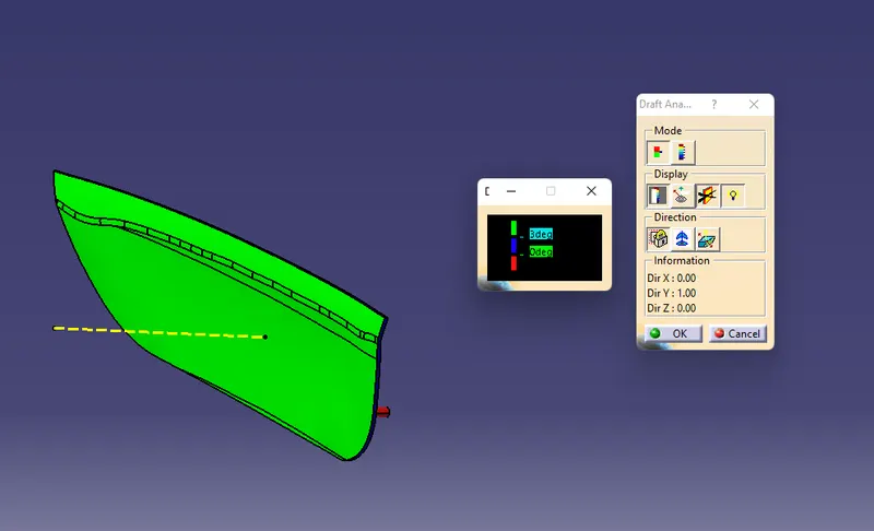
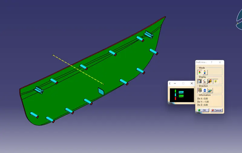
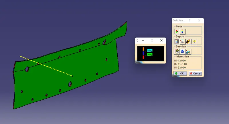
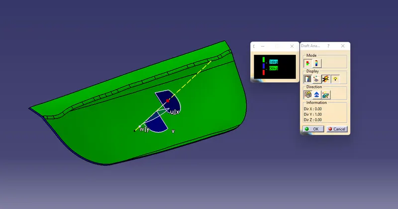
For Draft Analysis, we have to create the first Tooling Axis in which the maximum area of the surface is cleared for draft analysis.
The Mechanics of Locating
A workpiece free in space can move in an infinite number of directions. For analysis, this motion can be broken down into twelve directional movements, or "degrees of freedom." All twelve degrees of freedom must be restricted to ensure proper referencing of a workpiece.
As shown in Figure 3-1, the twelve degrees of freedom all relate to the central axes of the workpiece. Notice the six axial degrees of freedom and six radial degrees of freedom. The axial degrees of freedom permit straight-line movement in both directions along the three principal axes, shown as x, y, and z. The radial degrees of freedom permit rotational movement, in both clockwise and counterclockwise radial directions, around the same three axes.
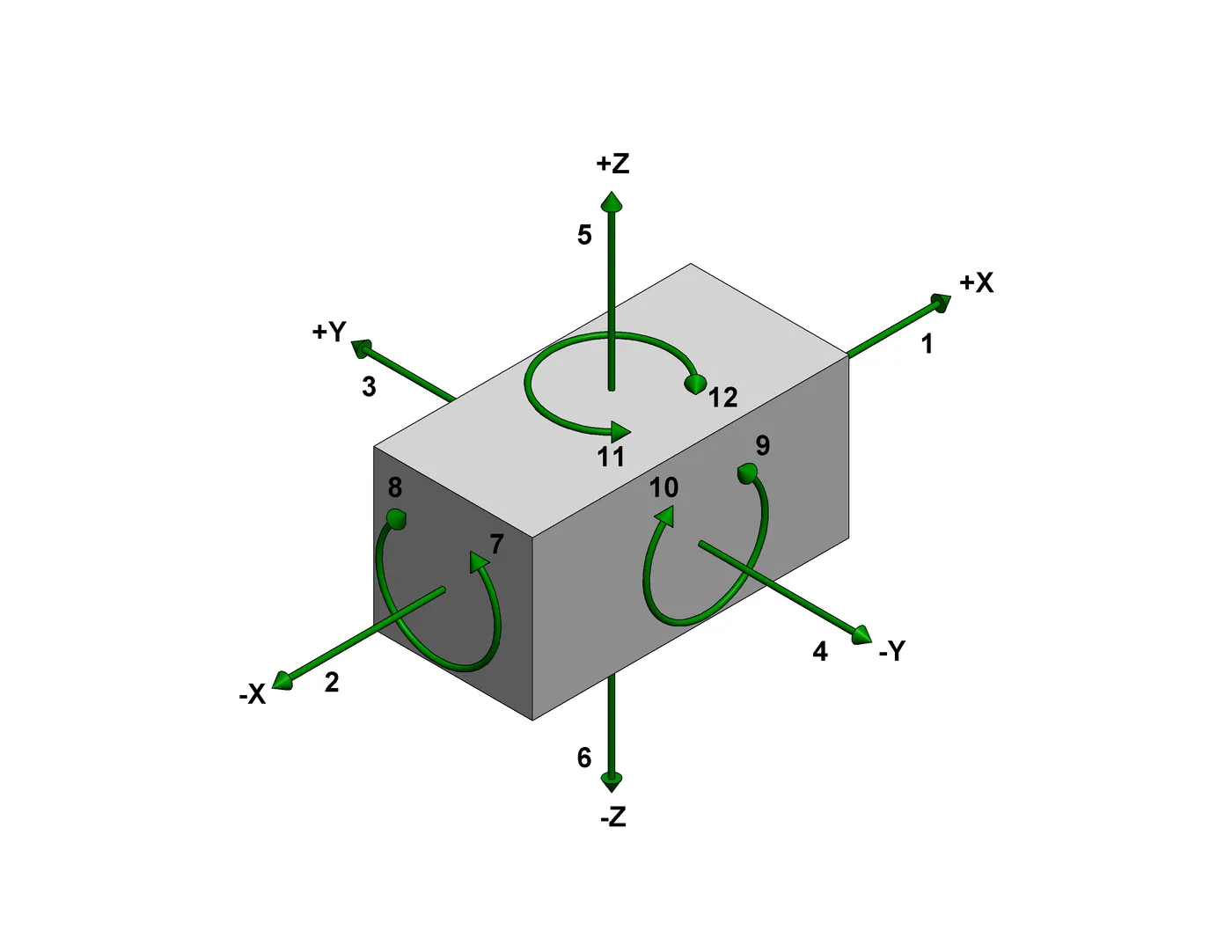
The twelve degrees of freedom.
The devices that restrict a workpiece's movement are the locators. The locators, therefore, must be strong enough to maintain the position of the workpiece and to resist the cutting forces. This fact also points out a crucial element in workholder design: locators, not clamps, must hold the workpiece against the cutting forces.
Locators provide a positive stop for the workpiece. Placed against the stop, the workpiece cannot move. Clamps, on the other hand, rely only upon friction between the clamp and the clamped surface to hold the workpiece. Sufficient force could move the workpiece. Clamps are only intended to hold the workpiece against the locators.
Forms of Location
There are three general forms of location: plane, concentric, and radial. Plane locators locate a workpiece from any surface. The surface may be flat, curved, or have an irregular contour. In most applications, plane-locating devices locate a part by its external surfaces, Figure 3-2a. Concentric locators, for the most part, locate a workpiece from a central axis. This axis may or may not be in the center of the workpiece. The most common type of concentric location is a locating pin placed in a hole. Some workpieces, however, might have a cylindrical projection that requires a locating hole in the fixture, as shown in Figure 3-2b. The third type of location is radial. Radial locators restrict the movement of a workpiece around a concentric locator, Figure 3-2c. In many cases, locating is performed by a combination of the three locational methods.
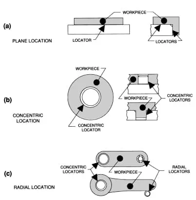
The three forms of location: plane, concentric, and radial.
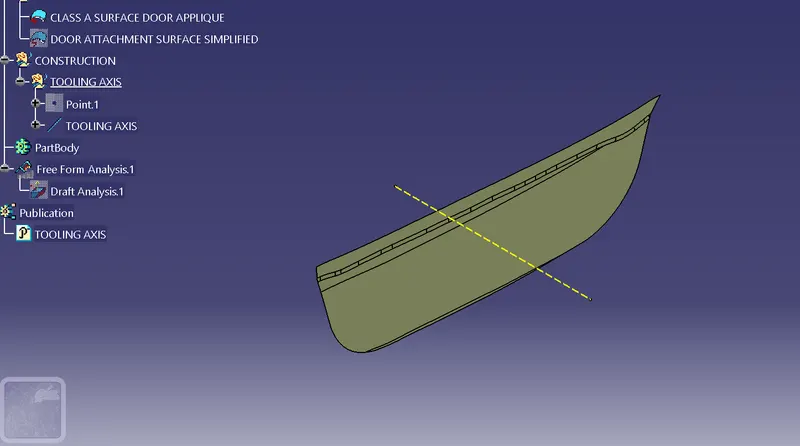
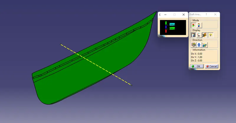
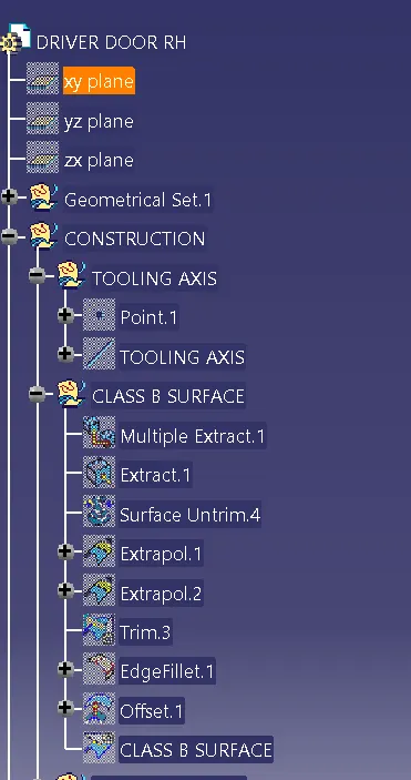
- Draft Analysis performed on Class A Surface and Publish the Tooling Axis and Class A Surface.

Creation of Class B Surface
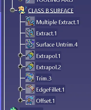
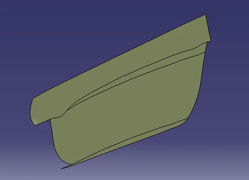
- Multiple Extract the Class A surface for the creation of a class B Surface.
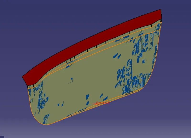
- Extract the top surface
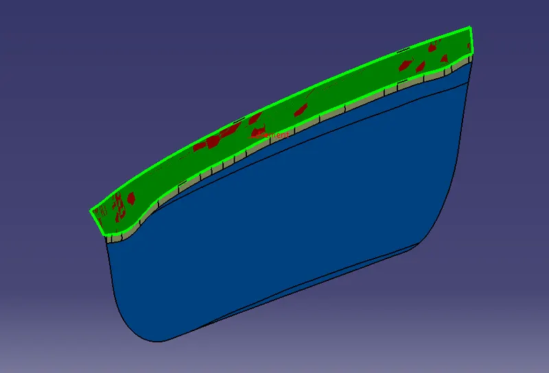
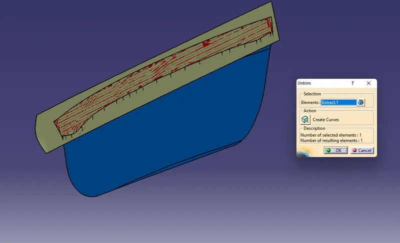
- Untrim and Extrapolet the surface
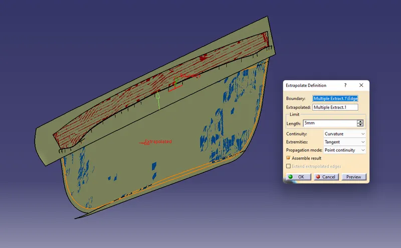
- Extrapolate both surfaces so both surface intersect with each other properly using point continuity.
- Untrim Both extrapolates.
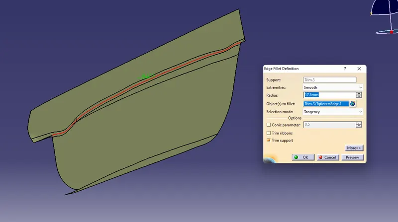
- Use Edge Fillet of 15mm + 2.5mm
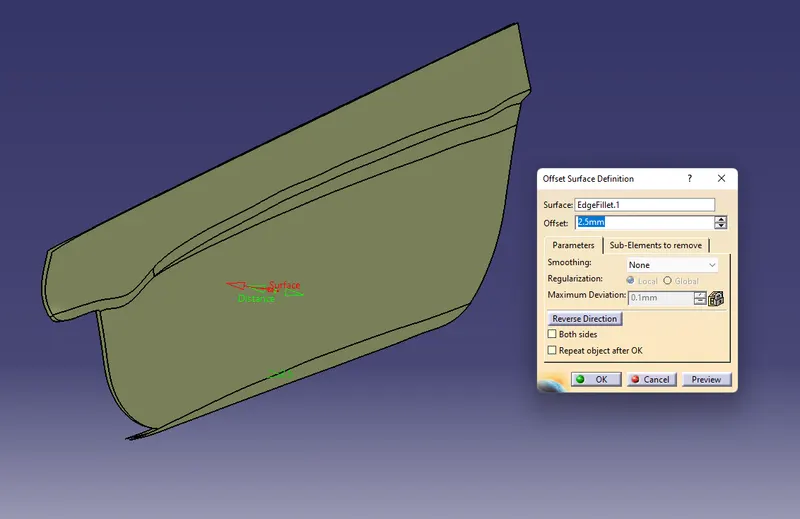
- Then Offset it 2.5mm
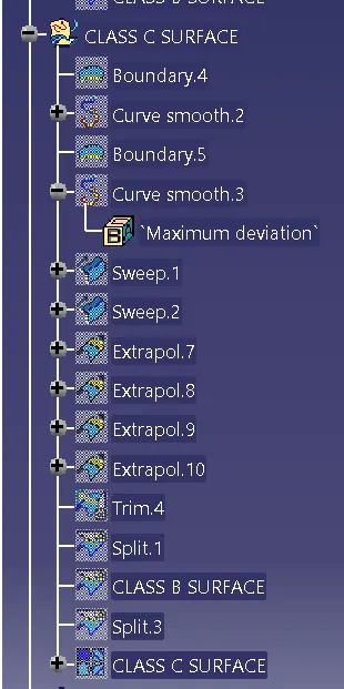
3. Creation of Class C Surface
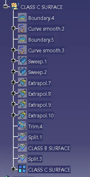
- Take the boundary of the Class A Surface with Limits and Two separate boundaries
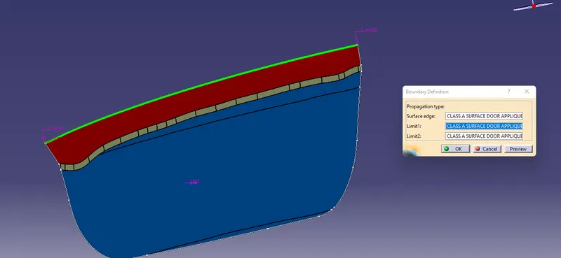
- Use Sweep command with draft Direction for creation of Sweep surface with outside direction and 3degree angle.
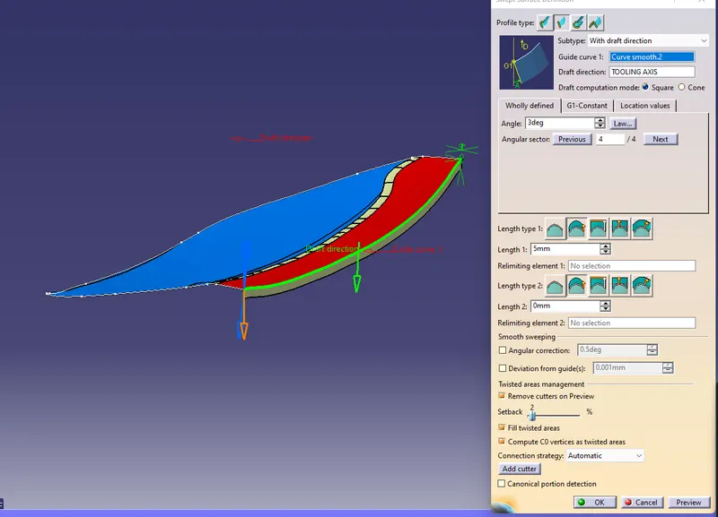
- Use Sweep command with draft Direction for creation of Sweep surface with outside direction and 3degree angle and 4mm in length.
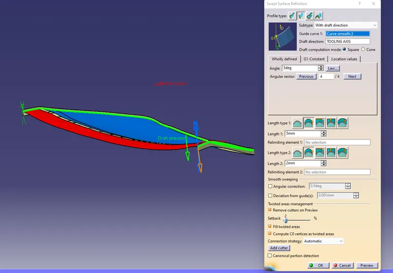
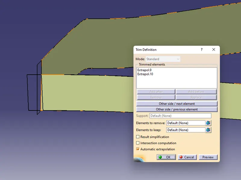
- For proper Joining of sweep extrapolate both sides and trim them
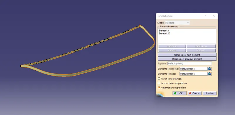
- Join the sweep and Class-A surface and Trim it with Class B surface which we cerated
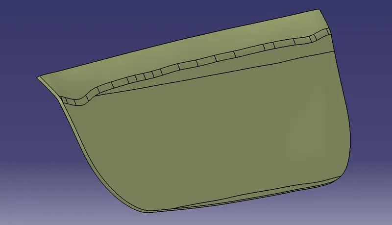
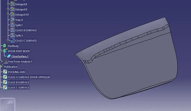
After that create the close to surface of the surface and Publish all surfaces
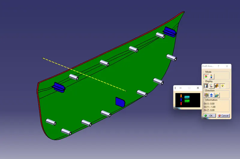
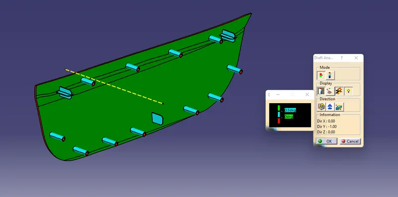
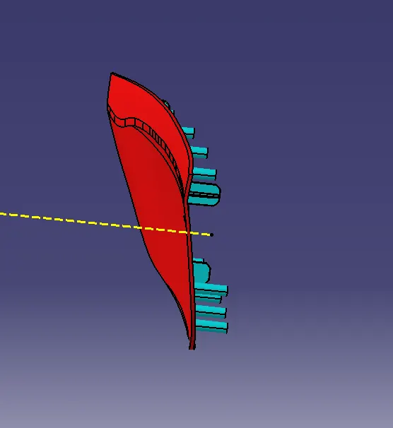
Draft Analysis on Closed Surface
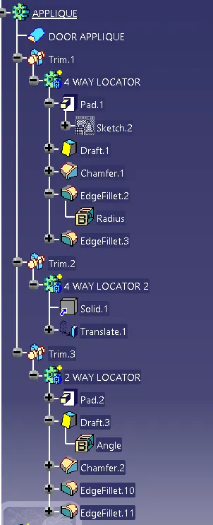
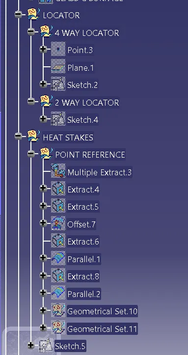
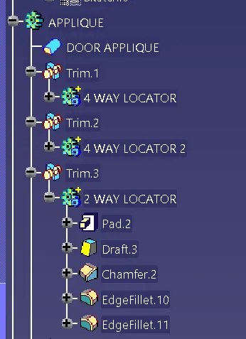
Create Sketch on ZY plane of a 4-way locator to arrest multiple DOF
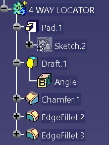
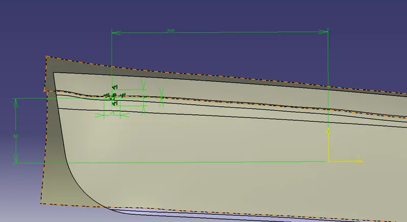
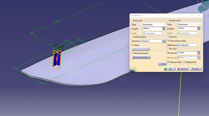
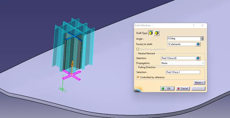
Provide Draft of 0.5 Degree
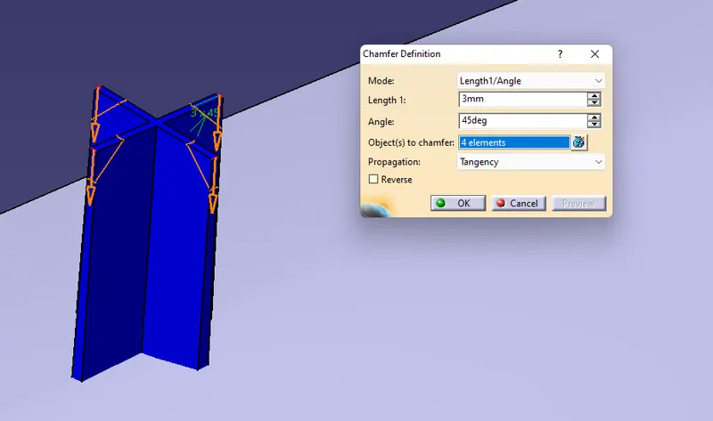
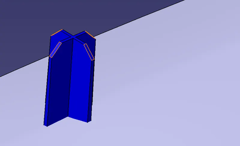
Provide Chamfer of 1mm to 45degree
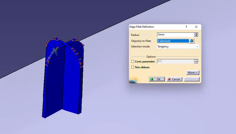
Provide Edge fillets to provide smooth edges
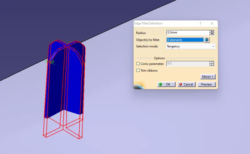
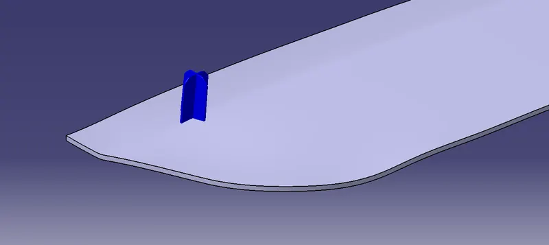
After creating this 4-way locator Create a copy with a special link and translate this same 4-way locator to another side of the Door Applique Panel
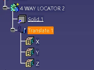
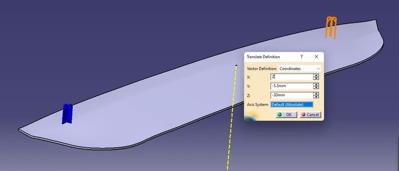
Translate with Coordinate values
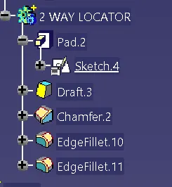
Now we have to create a 2-way Locator on Door Applique
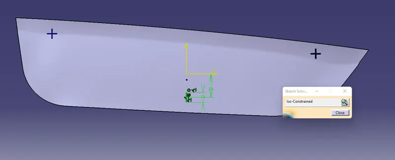
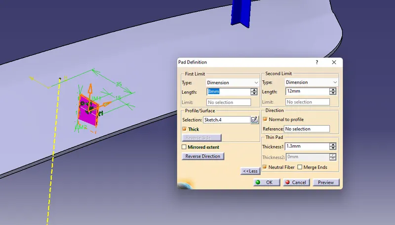
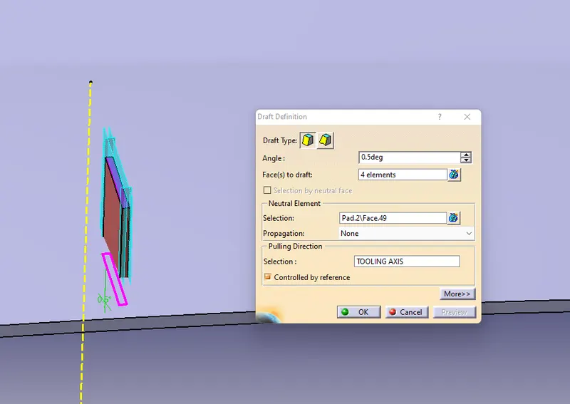
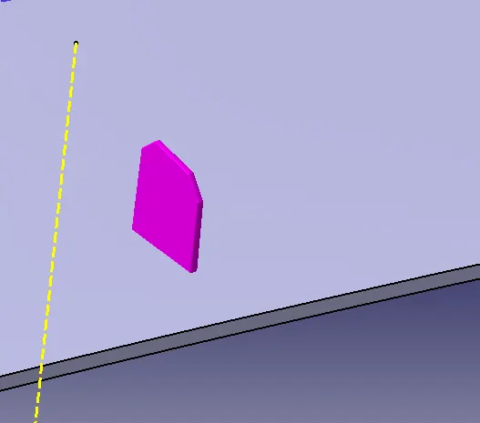
Now using UnTrim Command Trim the extra surface which is created on another side of Applique
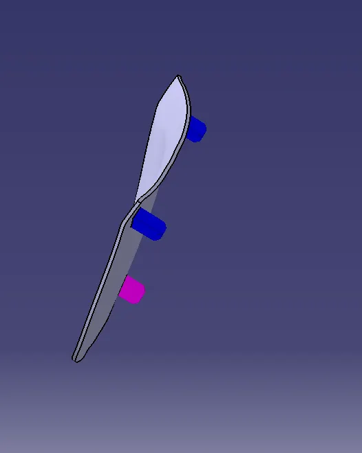
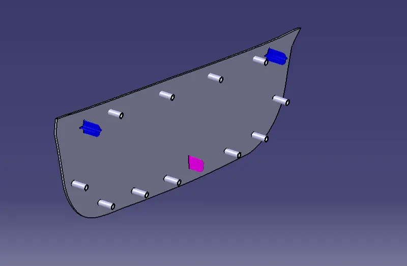
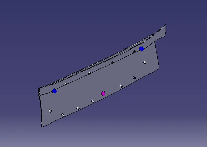
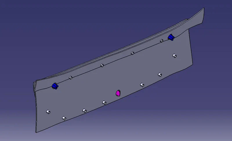
Now its time to create Heat Stakes Surrounding on Door Applique
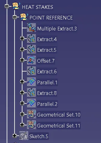
Extract the parallel lines to 15mm from the boundaries of the Door Applique but make sure its points do not intersects our locators.

Sketch for Heat Stakes
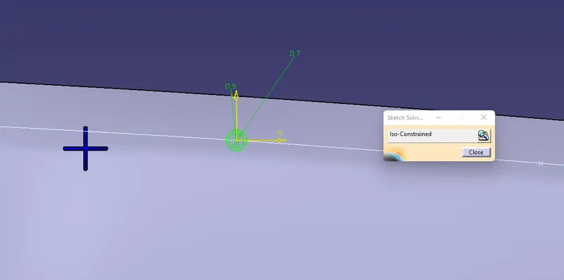
Pad the sketch and give a draft angle of 0.5 degree
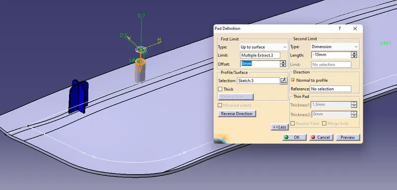
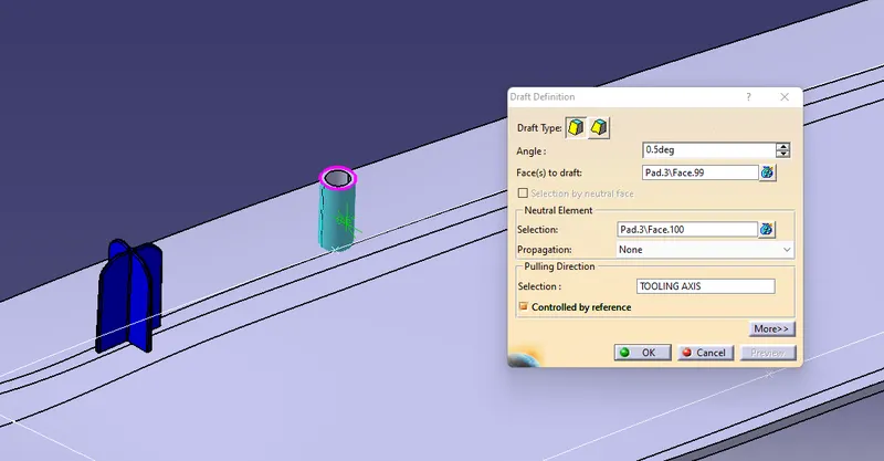
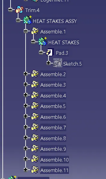
Translating the Copy of the first heat stakes to other positions.
- Copy the Body of the 4 heat stakes.
- Special paste it on the main tree.
- Translate the body with a point-to-point translation definition.
- Follow this for all remaining position of heat stakes
- Assemble all the heat stakes bodies to one Body.
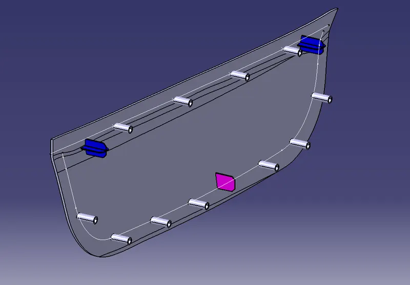
PROCEDURE FOR CREATING CLEARANCE HOLE FROM LOCATORS:
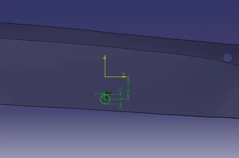
STEP 1: Sketch for clearance hole to be made on attachment surface for locators.
© Copy and paste the same sketch of the first 4-way locator.
o Make all the lines as construction lines.
o Add a circle 14.7 mm Diameter.
• NOTE: The length of both lines of the 4-way locator was 15mm.
• NOTE: The diameter of this circle is 14.7mm, so we are reducing 0.15 mm clearance to both sides on the sketch, so dia will be
15mm-0.15mm-0.15mm = 14.7mm.
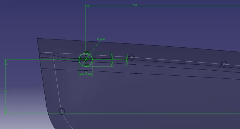
and now perform boolean operation to remove that provide clearance to locator
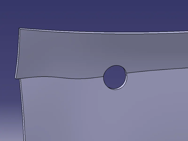
Perform similar steps to the second 4-way locator
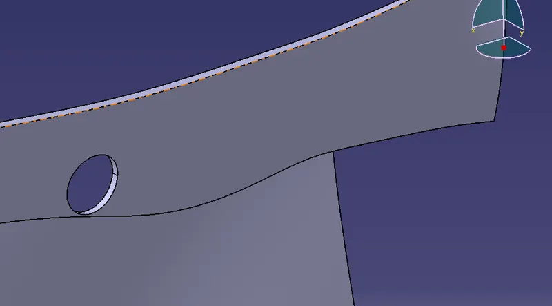
Perform same procedures for 2 way locator also
PROCEDURE FOR CREATING CLEARANCE HOLE FROM HEAT STAKES :
STEP 1: Sketch for clearance hole to be made on attachment surface.
© Copy and paste the same sketch of heat stake.
o Remove the inner diameter of the heat stake.
o Increase outer dia (clearance circle) to 7.2 mm
• NOTE: The outer dia of heat stakes was 7mm, so we are providing 0.1 mm clearance to both sides on the clearance hole sketch, so dia will
be 7.2mm.
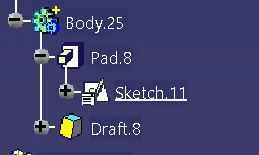
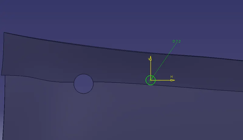
Use pad feature
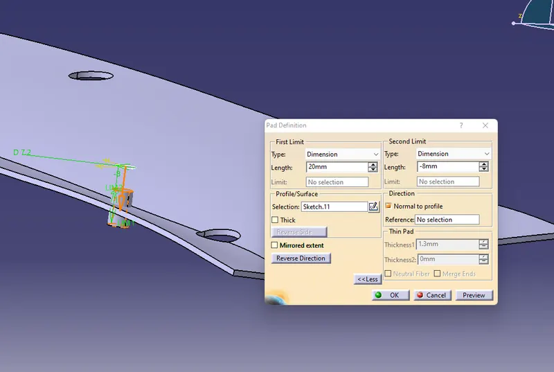
Translating the Copy of the clearance hole body to the same position of all heat stakes.
• Copy the Body of the clearance hole body.
• Special paste it on the main tree.
• Translate the body with a point-to-point translation definition.
• Follow this for all remaining positions where heat stakes are placed.
• Assemble all the clearance hole bodies into one Body.
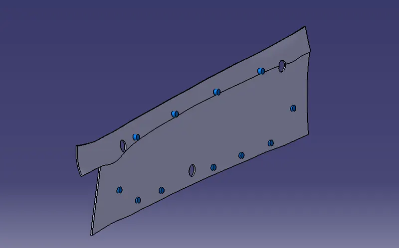
Now Use Boolean Operation of remove and create provide clearance to heat stakes
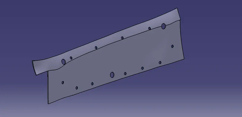
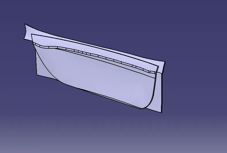
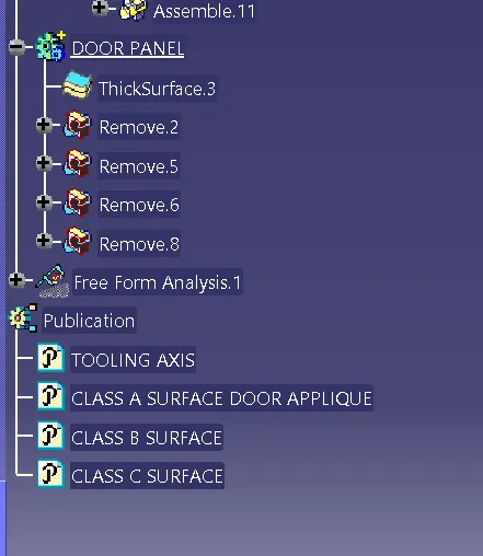
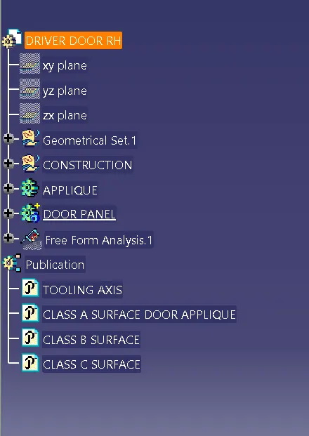
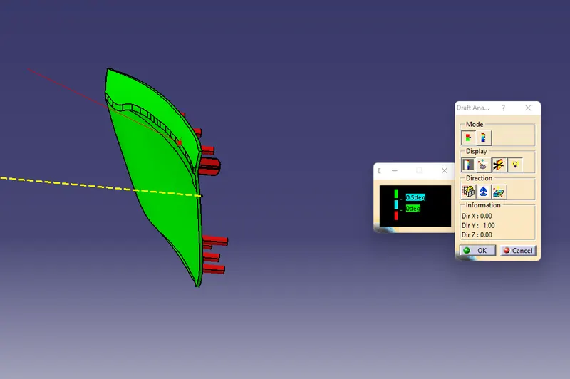
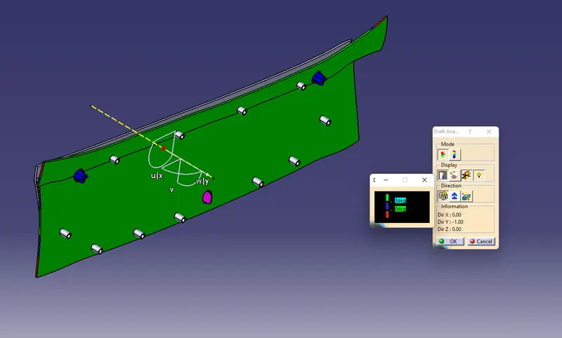
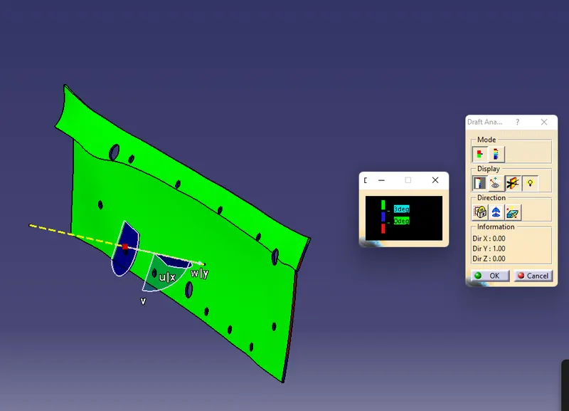
Draft Analysis performs on Door Panel and Door Applique