Advanced Sheet Metal Design Using NX Cad Challenge_1_Casing Design
Advanced Sheet Metal Casing Design Using NX Cad
Objective: In this Advanced Sheet Metal Design Course using NX we design our first model of Casing Design using Sheet Metal Applications in NX Cad. We learned Basic Tools used for CAsing Design in the Sheet Metal Section of NX Cad.
Introduction: Sheet metal is metal formed by an industrial process into thin, flat pieces. Sheet metal is one of the fundamental forms used in metalworking, and it can be cut and bent into a variety of shapes. Countless everyday objects are fabricated from sheet metal. Thicknesses can vary significantly; extremely thin sheets are considered foil or leaf, and pieces thicker than 6 mm (0.25 in) are considered plate steel or "structural steel".
Many different metals can be made into sheet metal, such as aluminum, brass, copper, steel, tin, nickel, and titanium.
Application:
- Automobile
- Aerospace Industries
- Utensils In Domestic Purposes
- Many Industrial Applications
- Electrical Application
Design Methodology: In this Casing Design we use some basic features like Tab, Flange, Normal Cutout, Dimple, Bead, Bend, etc.
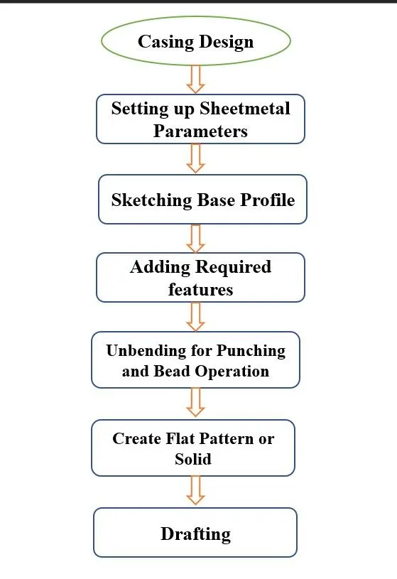

Features Used in Casing Design:
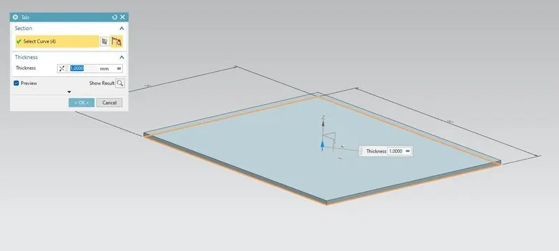
1. Tab Features: It is similar to Extrude Feature. We can use Set parameter values or we can also be able to use Local values which we needed. To Execute this command base profile sketch is required.
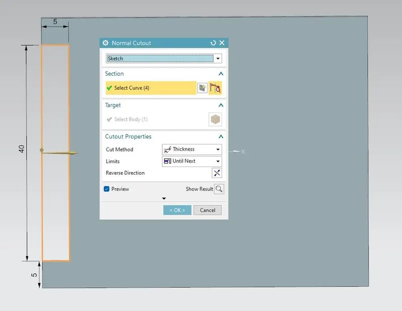
2. Normal Cutout: This Feature is similar to Extruded Cut feature in this feature we should have to draw or sketch or draw a profile that we want to cut from our model to execute this feature we need a base sketch profile that we cut using the normal cutout option.
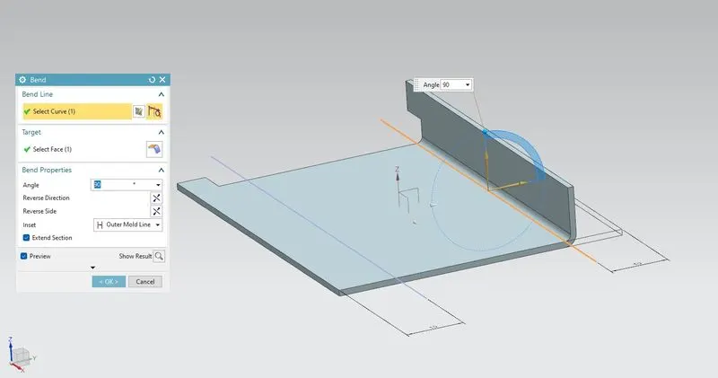
3. Bend: This Feature help to bend our sheet metal at the particular edge or where we can bend our sheet metal to get desired structure. also we can give angle dimension to our bend feature also we can adjust the length bend radius, etc.
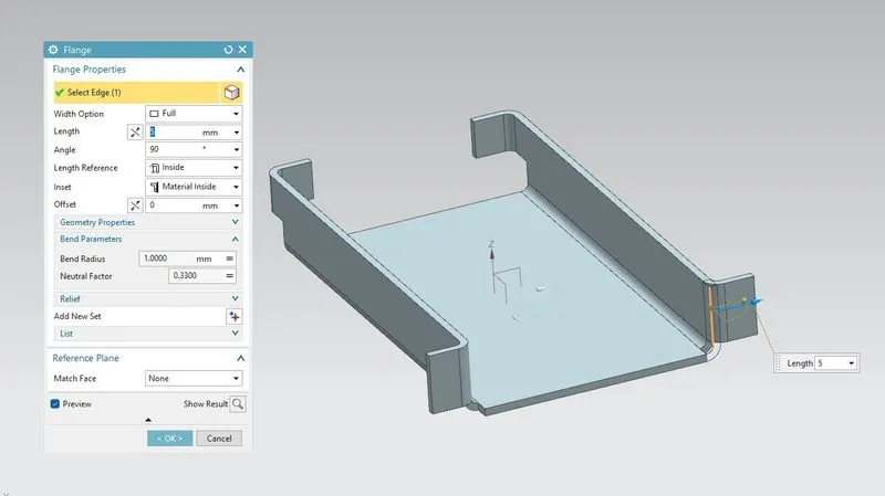
4. Flange: This feature is used to get flanged at the planer face we have to select the edge where we want flange we can control bend radius, Length, Angle of flange direction where we want also we can choose where we want to flange outside or inside of the material to proper use of sheet metal in Industries.
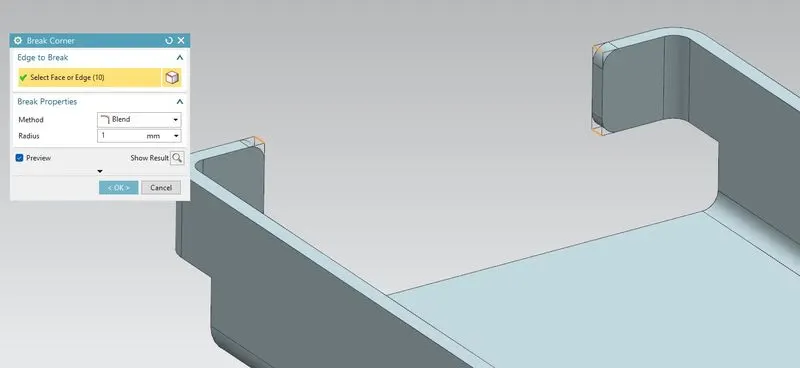
5. Break Corner: Break Corner is similar to the fillet feature we use this feature to give a rounding edge profile to our sheet metal or model. Also to remove the sharp edges in our profile we use the break corner feature in sheet metal we have to give a radius value for this to get a rounded corner.
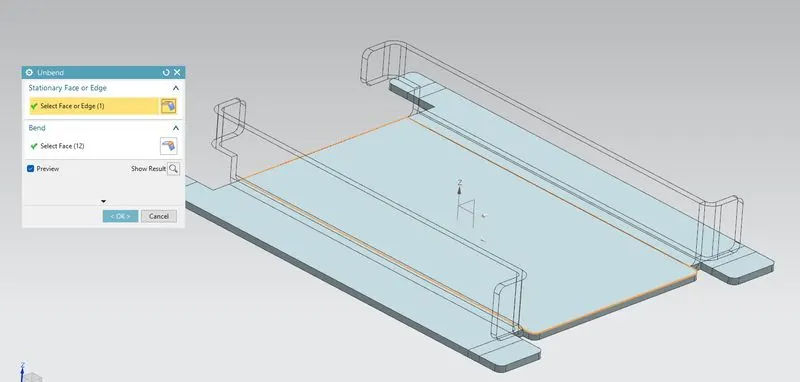
6. Unbend: Unbend feature is very useful while we creating holes, giving dimples or beads in our sheet metal. This feature helps users to locate the feature at the exact location without any trouble and give us an idea of where is flange and where is sheet metal is exactly bent so using or seeing this we adjust our hole or bead or dimple. this feature unbends all flanges and bend features into a flat surface and also helps to visualize the before and after the shape of sheet metal.
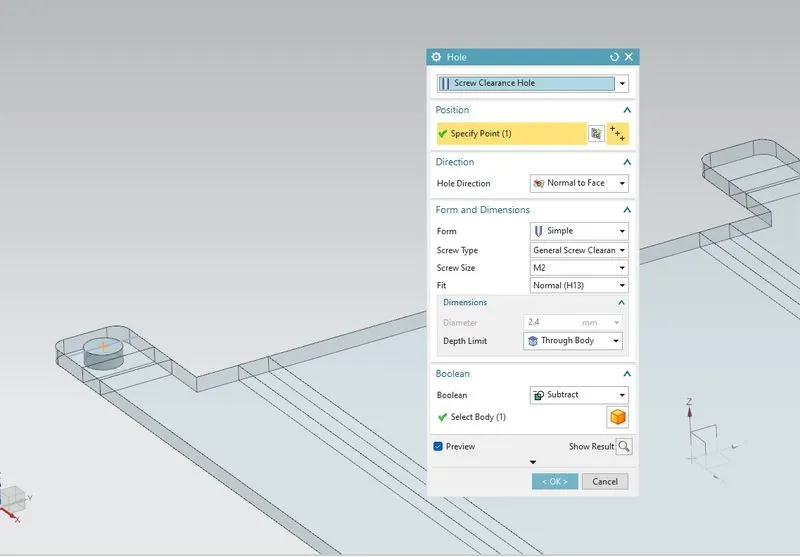
7. Hole Features: This feature is used to create holes in our casing design as required we can select the type of hole, size of the hole, square-headed or rounded we can customize the hole set as per customer requirement and our design specification.
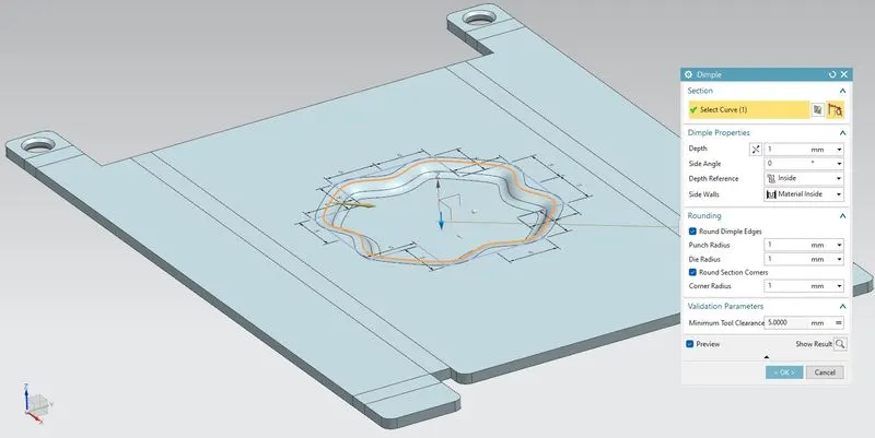
8. Dimple: This Command is used for embossing something on our sheet metal design or draw a sketch and use this feature to get the stamping tool feature on our model. For embossing something we need to draw or sketch some profile that we want to stamp on our sheet metal panel.
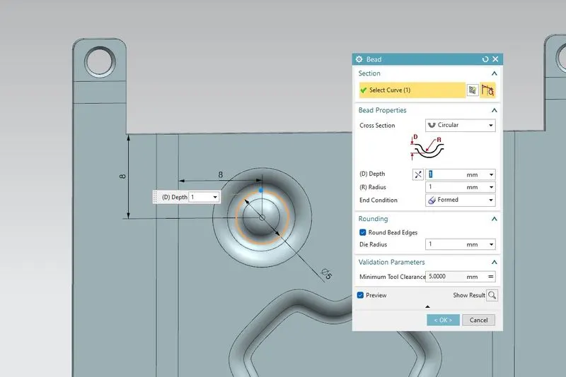
9. Bead: This feature stimulate stamping tool this feature lifts or embosses the sketch or profile we have drawn as per our requirement. This feature gives a curvy radius or rounded radius as per our requirement and setting we can also manage the depth, the radius of the sketch profile.
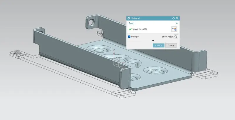
10. Rebend: This feature undo the unbending command and add all flanges, Bend, Dimple, Bead, and associate features we have created on sheet metal.
11. Drafting: It is a graphical representation of structures, machines, and their parts that communicates the engineering intent of a technical design to the craftsman or worker who makes the product. In drafting, objects are drawn to scale, and usually comprise a top view, the main view, and a side view of the object or building. They are usually very detailed and are often used as blueprints for the construction or assembly of the object. While they are sometimes used in engineering.
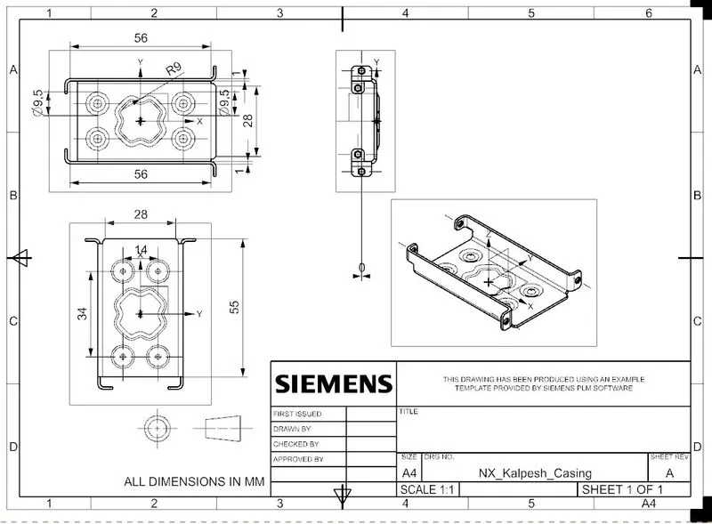
Casing Views
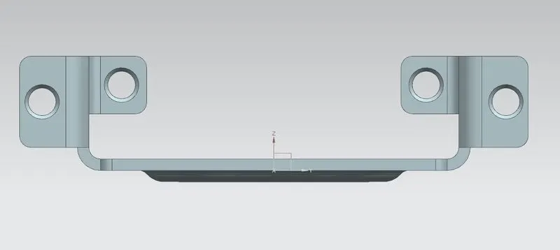
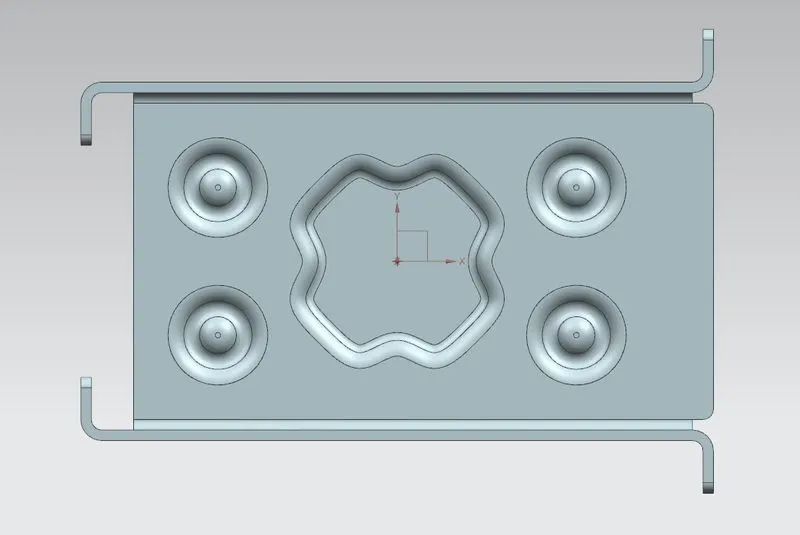
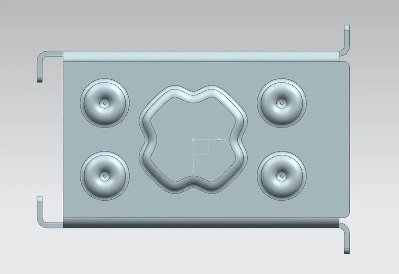
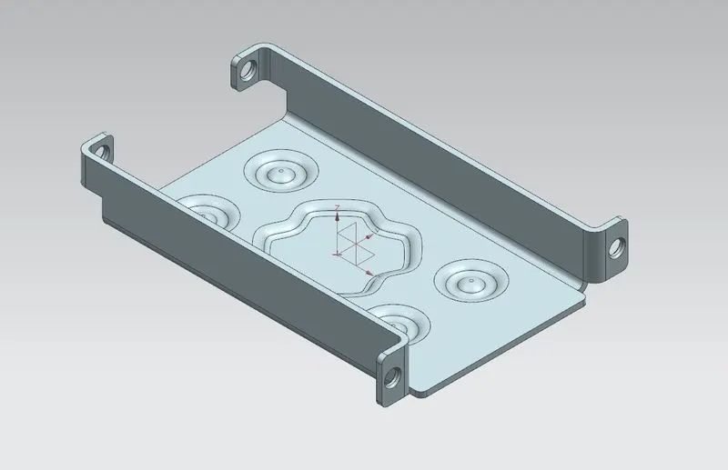
Conclusion: The Casing Design using NX cad is completed by using some basic features and sketch parameters and we learned the use of sheet metal features like Bead, Tab, flange, Dimple, Tab, Break Corner, Mirror feature, hole, etc.