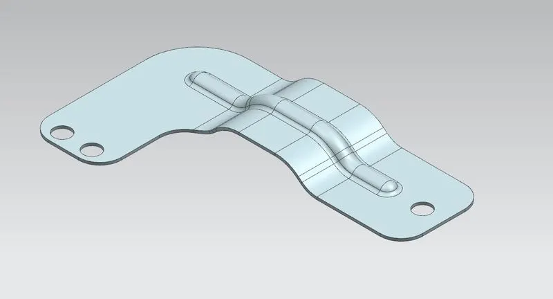
Advanced Sheet Metal Design Using NX Cad Challenge_6_Bracket
Bracket using NX Cad
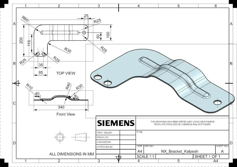
Objective: The main objective of this project is to design a sheet metal Bracket in Nx Cad, also to make the drafting of our Bracket.
Introduction: Sheet metal is metal formed by an industrial process into thin, flat pieces. Sheet metal is one of the fundamental forms used in metalworking, and it can be cut and bent into a variety of shapes. Countless everyday objects are fabricated from sheet metal. Thicknesses can vary significantly; extremely thin sheets are considered foil or leaf, and pieces thicker than 6 mm (0.25 in) are considered plate steel or "structural steel".
Bracket: These are manufactured by conducting stamping or die casting operations. These brackets found their application for mounting any products starting from antennas to TV, projectors or street lights, and many more.
Features we used in Bracket:
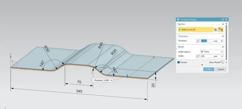
1. Contour Flange: It defines a single contour flange by selecting an open profile. Inventors can create contour flanges along an edge or edge loop. The inventor previews the flange material thickness along with the selected profile and toward the material of the selected edge. However, you can reverse the thickness direction.
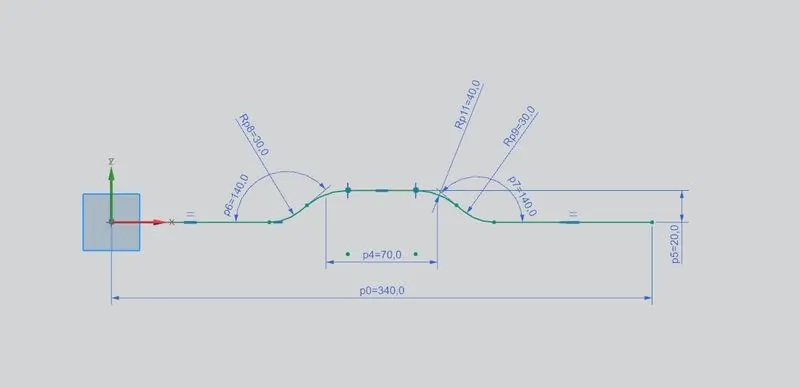
For making the Bracket first we created a base profile for our bracket on an XY plane with some dimensions.
For customer or manual type of sketch, we have to use contour flange feature in sheet metal and select the profile which we want to contour. and we created 200mm width and 1mm thickness of contour for our bracket and move further.
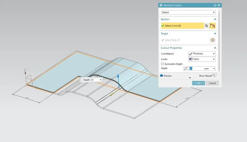
2. Normal Cutout: This Feature is similar to Extruded Cut feature in this feature we should have to draw or sketch or draw a profile that we want to cut from our model to execute this feature we need a base sketch profile that we cut using the normal cutout option.For removing some material or to acquired desired shape we make sketch on our XY Top plane and then use a Normal cutout to cut or remove that material from our bracket profile with a depth of 35mm.
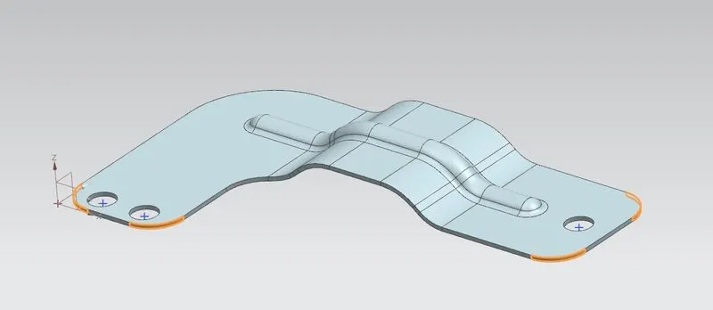
3. Break Corner: A break corner tool or chamfer tool is used to eliminate or remove sharp edges on our Bracket profile.
For our bracket, we use a break corner with a radius of 25 mm on the corner of the bracket and at the top side, we use a 60mm radius corner.

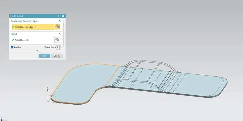
4. Unbend: Unbend feature is very useful while we creating holes, giving dimples or beads in our sheet metal. This feature helps users to locate the feature at the exact location without any trouble and give us an idea of where is flange and where is sheet metal is exactly bent so using or seeing this we adjust our hole or bead or dimple.
To creating Bead first we have to unbend our Bracket profile.
5. Bead: This tool is embossing or creates punch on the selected region or where we want with smooth curvature on the edge. On unbend face of our bracket we create a sketch with some dimensions and create a bead of 7mm in depth with 7mm of radius and this feature creates a smooth curve or radius on the edges of this 10mm radius.
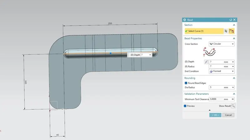
After successfully creating Bead we Rebend our bracket for the further procedure for making holes in the bracket.
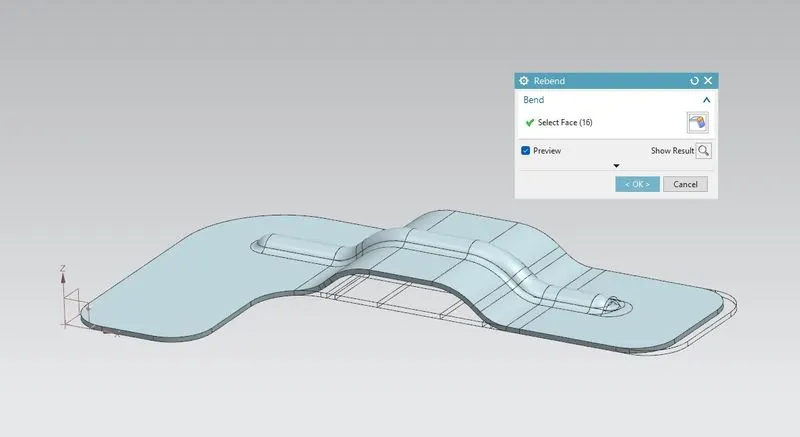
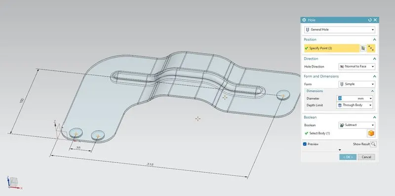
6. Hole: Hole command is used to create a hole on one or more solid where we want but before this, we have to create a point on the bracket where we want holes as per design requirement with proper dimension and we create a simple hole of 20mm depth of simple form.
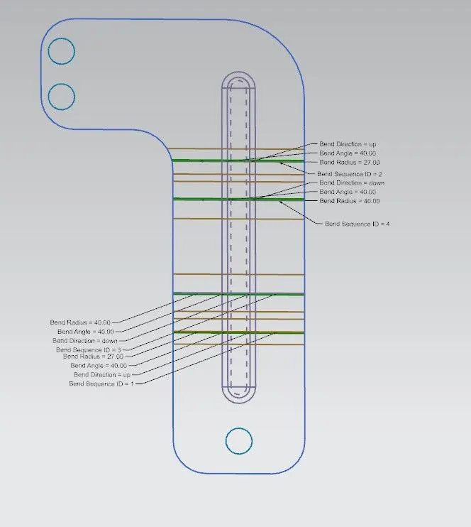
Front View
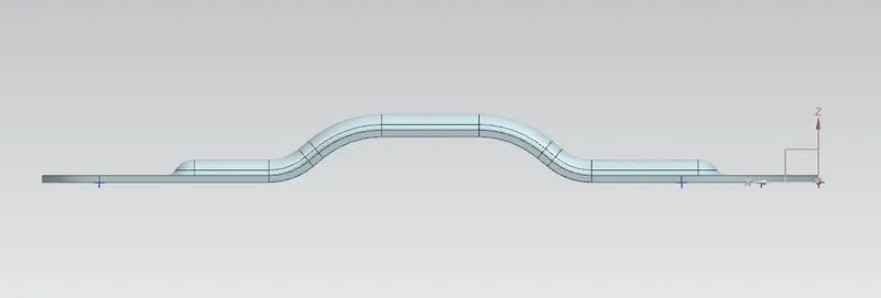
Top View
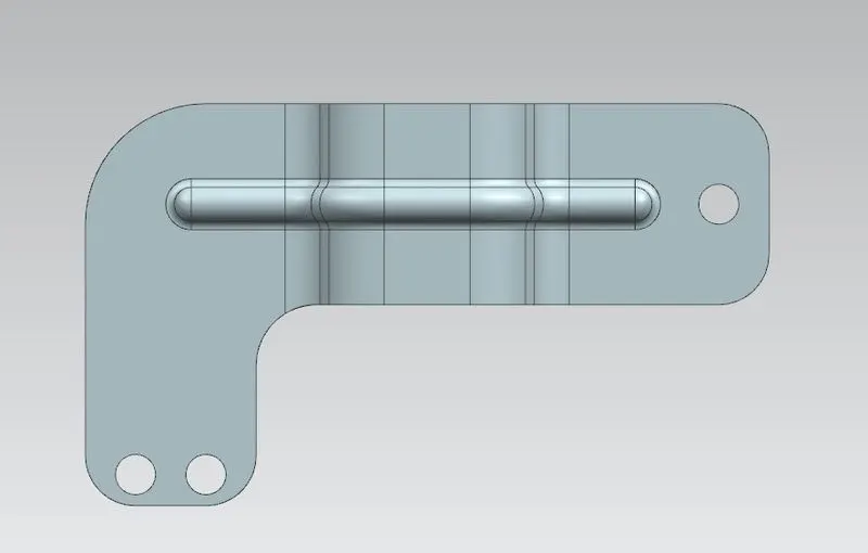
Bottom View
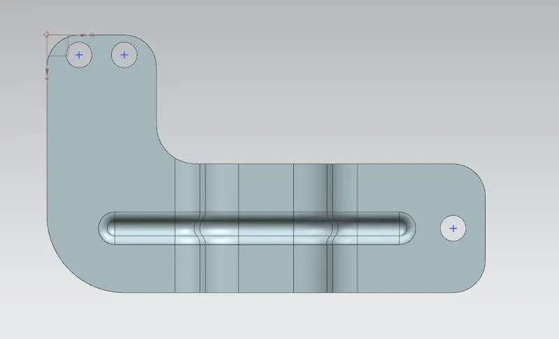
Isometric View