Photo Realistic Rendering
MODELLING AND PHOTOREALISTIC RENDERING OF AMERICAN CHOPPER USING SOLIDWORKS
OBJECTIVE:
- The main objective of this project is to learn and familiarise with the user interface, sketch tools, surface tools, and various features of Solidworks.
- To make part models of various parts of an American chopper bike.
- To bring in the final shape of the American chopper bike by assembling the various parts created.
- To familiarise with Solidworks visualize interface by performing a photorealistic rendering of the assembled American chopper bike.
INTRODUCTION:
There are various steps involved in the modeling of an American chopper. Firstly, the various parts of the American chopper are modeled using part modeling and then these parts are assembled together to create a final model of an American chopper bike.
The different parts assembled to create the chopper bike are as follows:
- Transmission belt
- Kickstand
- Front fender
- Rear fender
- Chain
- Oil Tank
- Pedal
- Front Wheel
- Rear Wheel
- Front Fork
- Chassis
- Engine
- Gas Tank
DESIGN METHODOLOGY:
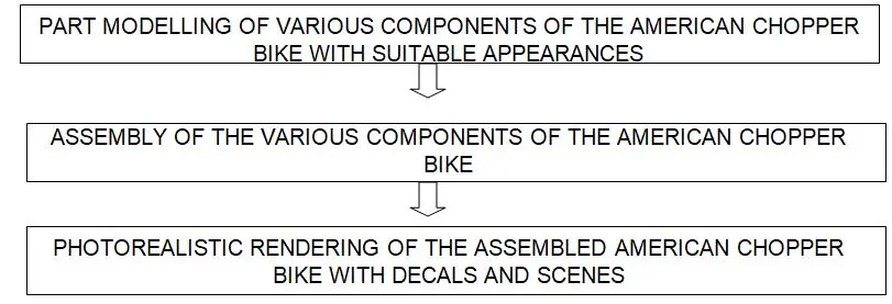
DESCRIPTION OF VARIOUS COMPONENTS AND FEATURES USED TO MODEL THOSE COMPONENTS
Part modeling
Part modeling enables the user to create a component with a 2d sketch and convert into the desired 3d shape using various features and also to make the modeled component visually appealing too.
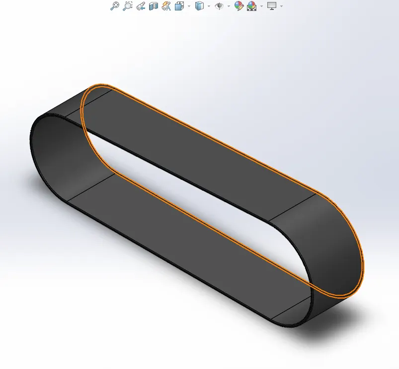
1.Transmission Belt
Transmission belt in general is used to transmit power from one end to another. In the case of the chopper bike, it is used to transfer the mechanical power from the engine to the gearbox. Transmission belts are generally made of rubber.
Features used to model Transmission Belt:
- Sketch
- Offset
- Boss extrude
- Fillet
- Appearance
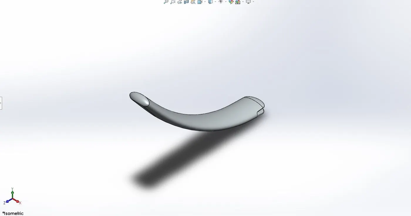
2.Kickstand
The kickstand is used majorly used in all the two-wheelers to keep them upright and to support the whole chassis when stationary.
Features used to model Kickstand:
- Sketch
- Loft
- Dome
- Split
- Cut extrude
- Boss extrude
- Fillet
- Appearance
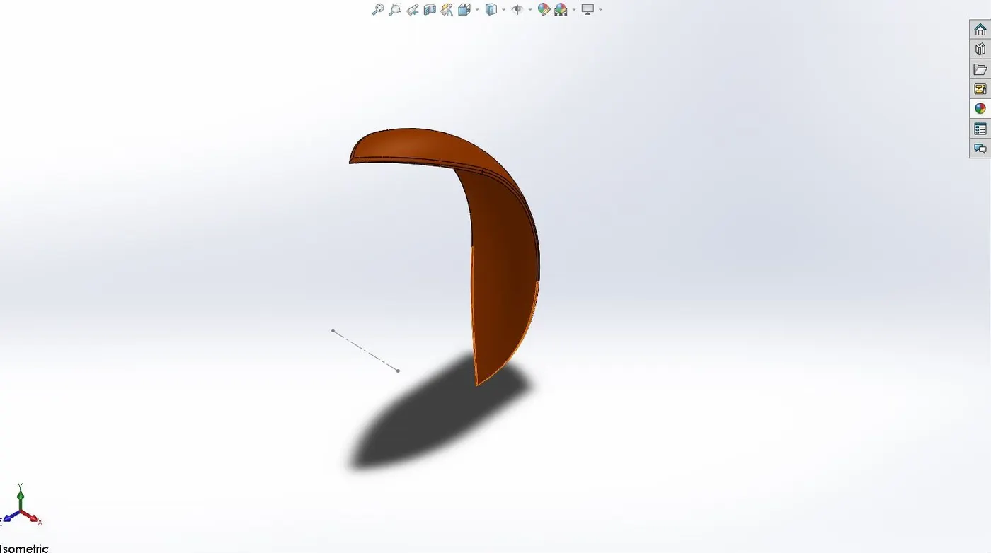
3.Front Fender
A front fender is used to protect the chopper from the stones and mud that is thrown up by the rotating wheel.
Features used to model Front Fender:
- Sketch
- Revolved boss
- Split
- Fillet
- Appearance
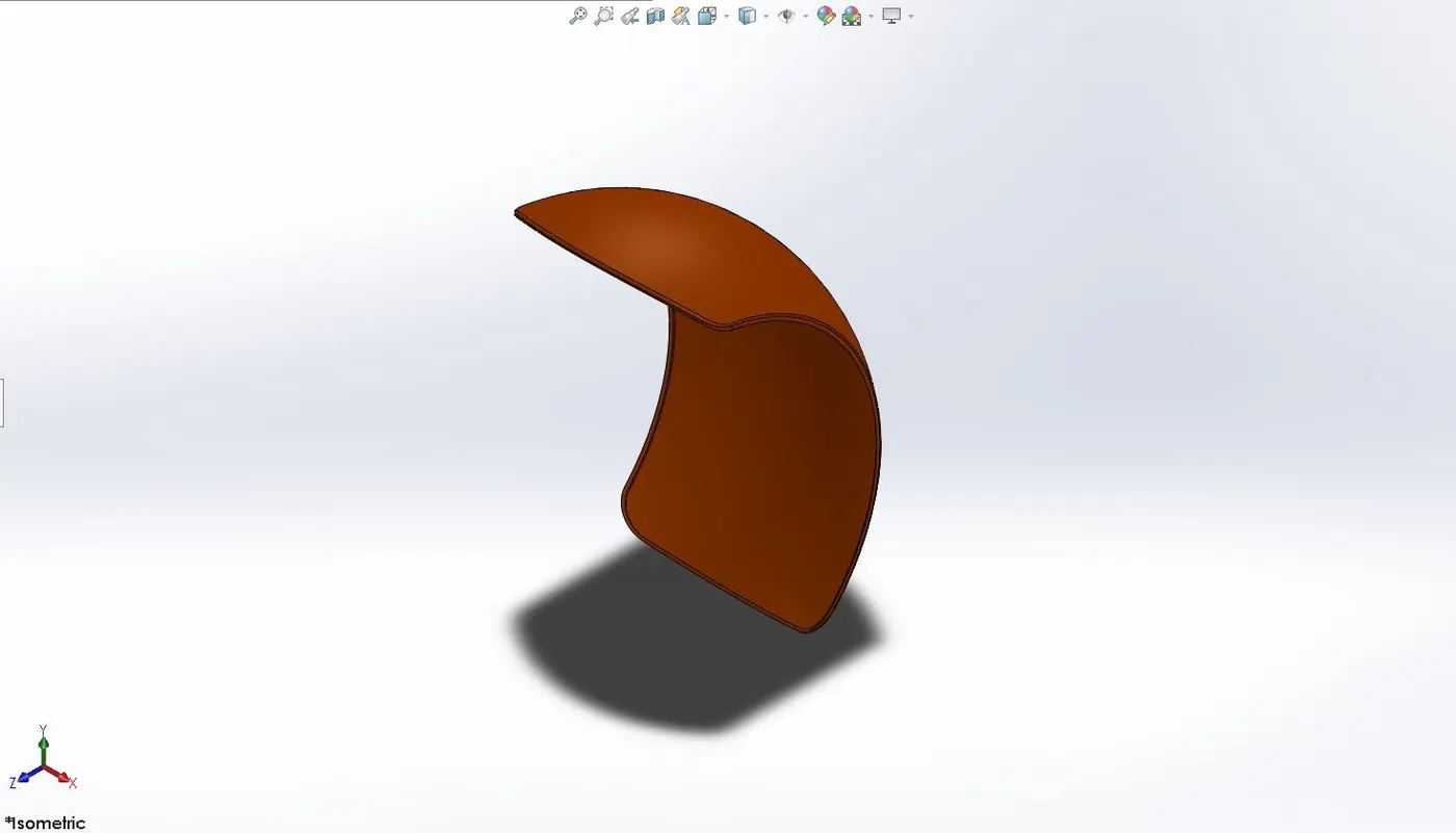
4.Rear Fender
A Rear fender is used to protect the chopper from the stones and mud that is thrown up by the rotating wheel.
Features used to model Rear Fender:
- Sketch
- Revolved boss
- Split
- Fillet
- Shell
- Appearance
5.Chain
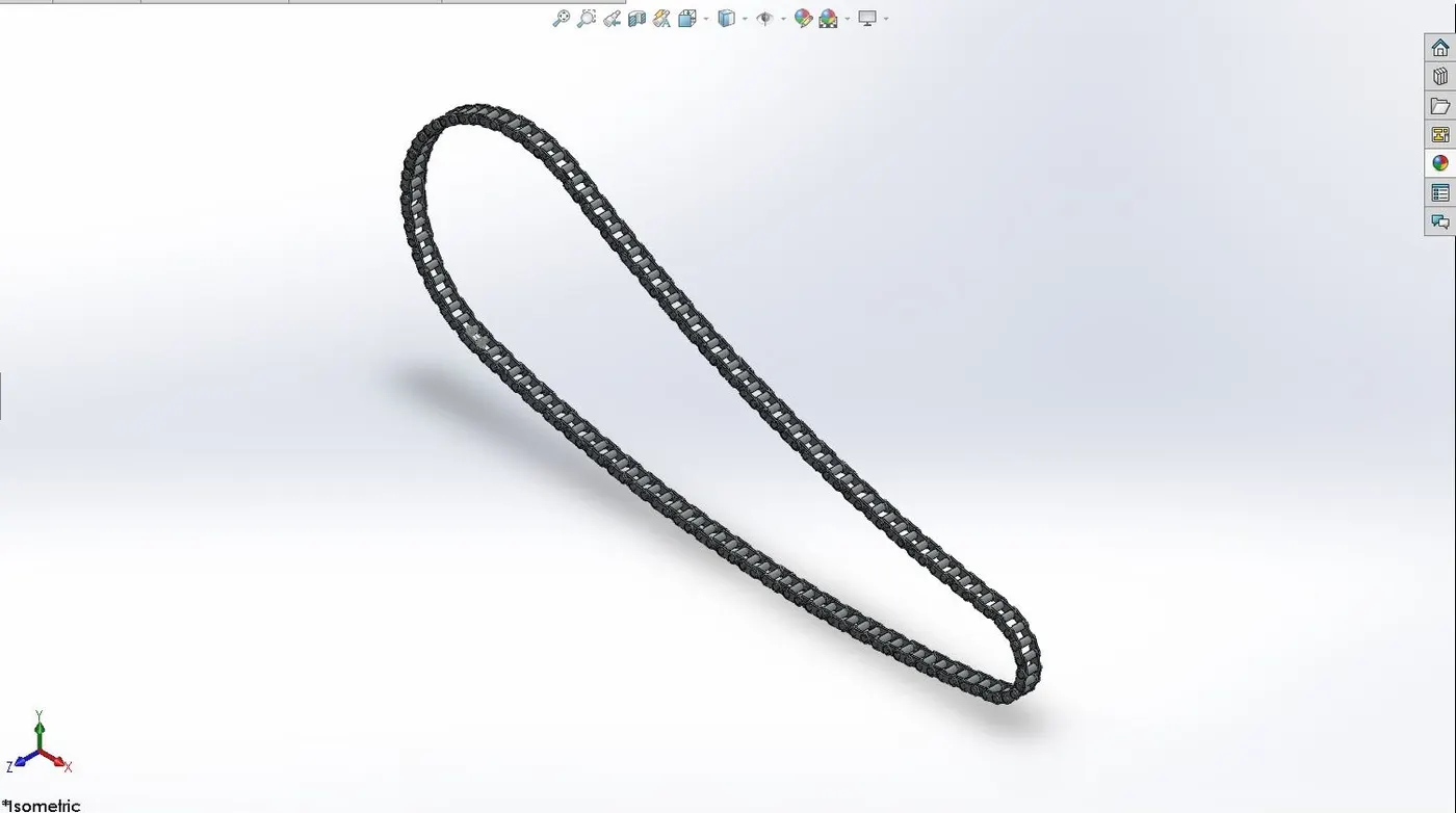
A chain is used to transmit power from the gearbox to the rear wheel.
Features used to model Chain:
- Sketch
- Sketch block
- Boss extrude
- Curve driven pattern
- Fillet
- Mirror
- Appearance
6.Oil Tank
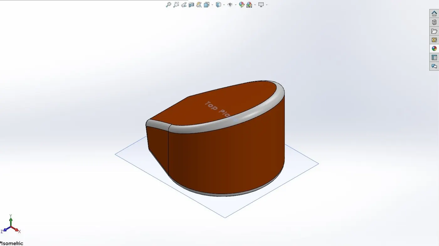
The oil tank is used to store lubrication oil in order to prevent the engine components from wearing and also used as a coolant.
Features used to model the Oil Tank:
- sketch
- Boss extrude
- Combine
- Fillet
- Shell
- Appearance
7.Pedal
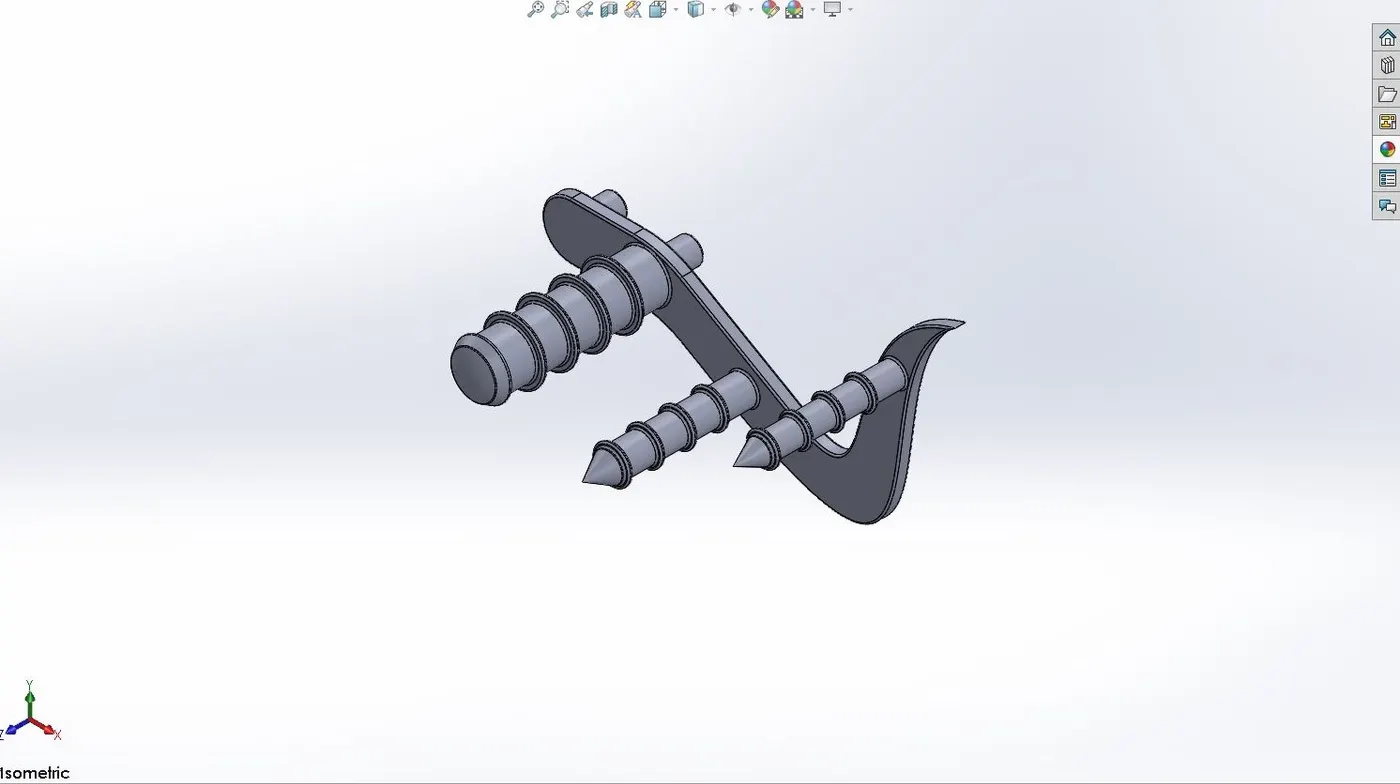
Foot pedals are generally used as brake control for the rear wheel, shifting of gears, and in some cases just to provide support to the legs of the rider.
Features used to model the Pedal:
- Sketch
- Boss extrude
- Revolved boss
- Linear pattern
- Fillet
- Chamfer
- Dome
- Appearance
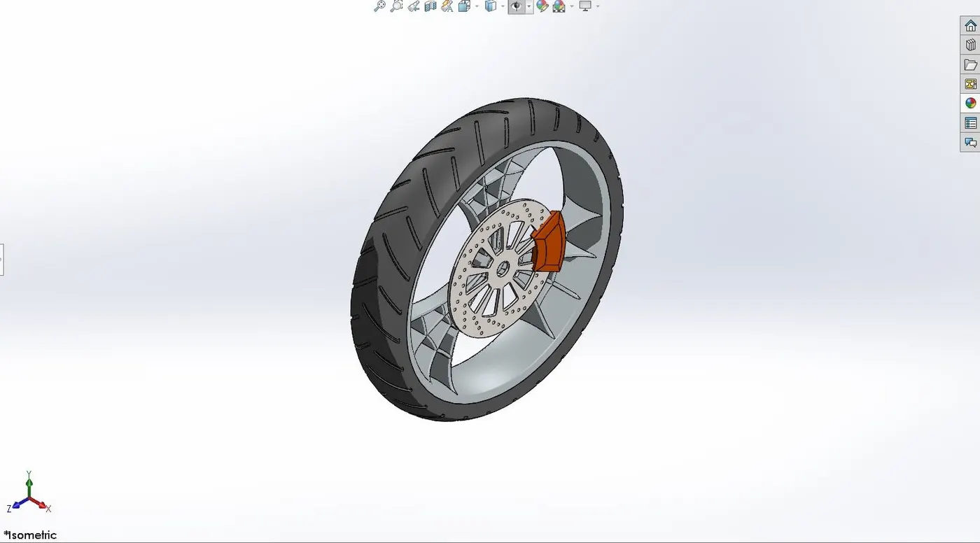
8.Front Wheel
A wheel is an important component in any automotive. It consists of a rim with which the chassis of the bike is connected and the tire mounted on the rim. The tire is a component made of rubber which makes contact with the surface and helping the bike to move forward.
A front wheel of an American Chopper consists of the following components:
- Rim
- Tire
- Rotor
- caliper
Features used to model the Front Wheel:
- Sketch
- Revolved boss
- Revolved cut
- Combine
- Fillet
- Boss extrude
- Cut extrude
- Chamfer
- Circular pattern
- Appearance
9.Rear Wheel
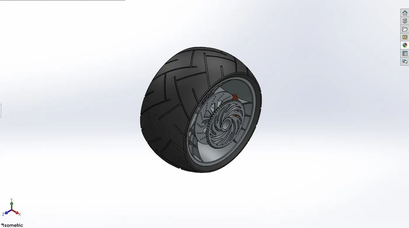
A wheel is an important component in any automotive. It consists of a rim with which the chassis of the bike is connected and the tire mounted on the rim. The tire is a component made of rubber which makes contact with the surface and helping the bike to move forward.
A Rear wheel of an American Chopper consists of the following components:
- Rim
- Tire
- Rotor
- Calliper
- Chain Sproket
Features used to model the Rear Wheel:
- Sketch
- Revolved boss
- Revolved cut
- Combine
- Fillet
- Boss extrude
- Cut extrude
- Chamfer
- Circular pattern
- Appearance
10.Front Fork
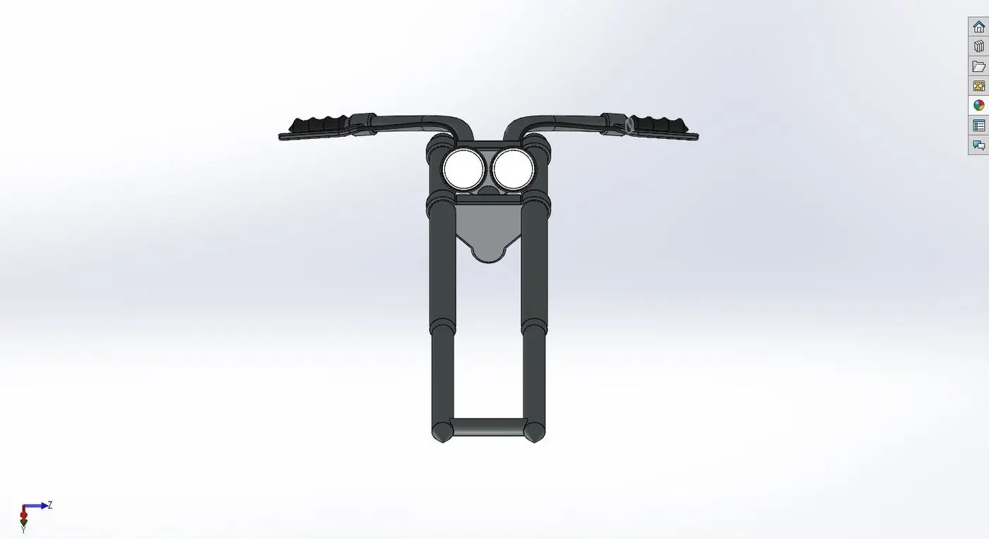
A front fork in a bike is used for multiple purposes. First, a front fork is used for the directional handling of the bike. It also houses the suspension, lights, and mounting point to attach the front wheel rim.
Features used to model the Front Fork:
- Sketch
- Revolve boss
- Extrude
- Linear pattern
- Fillet
- Dome
- Body move/copy
- Project curve
- Mirror
- Combine
- Sweep
- Plane
- Cut extrude
- Revolved cut
- Appearance
11.Chassis
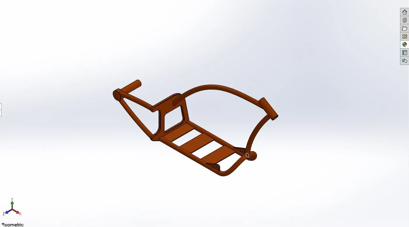
The chassis is the main skeleton structure of an American chopper bike. It is a hollow tube structure that supports every other component of the chopper bike.
Features used to model the Chassis:
- Sketch
- Sketch picture
- Project curve
- Sweep
- Mirror
- Boss extrude
- Cut extrude
- Chamfer
- Fillet
- Reference plane
- Dome
- Combine
- Split
- Revolved
- Appearance
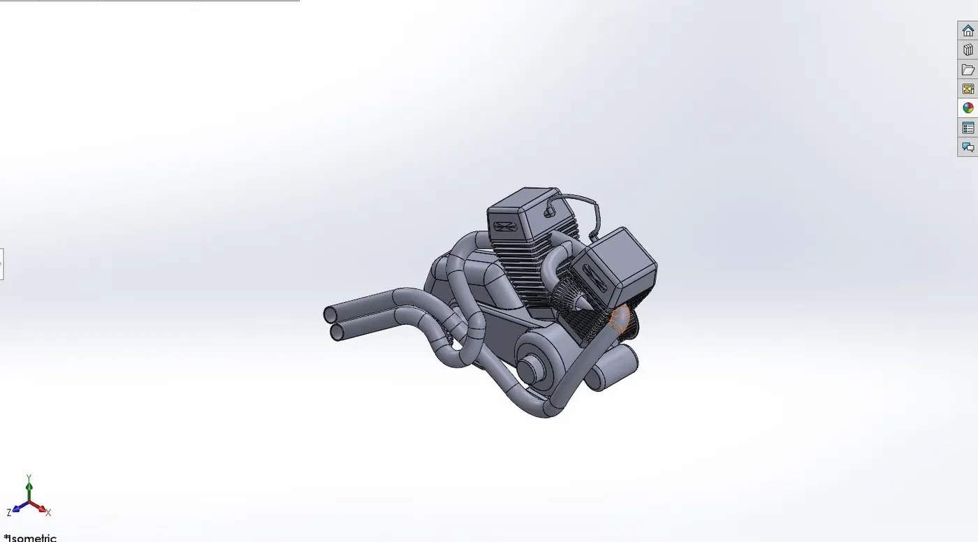
12.Engine
The engine is the heart of an American chopper which gives the mechanical power to propel the vehicle forward.
Features used to model the Engine:
- Sketch
- Sketch picture
- Boss extrude
- Fillet
- Revolved boss
- Circular pattern
- Dome
- Cut extrude
- Reference plane
- Chamfer
- Linear pattern
- Mirror
- Split
- Sweep
- Combine
- Project curve
- Composite curve
- Appearance
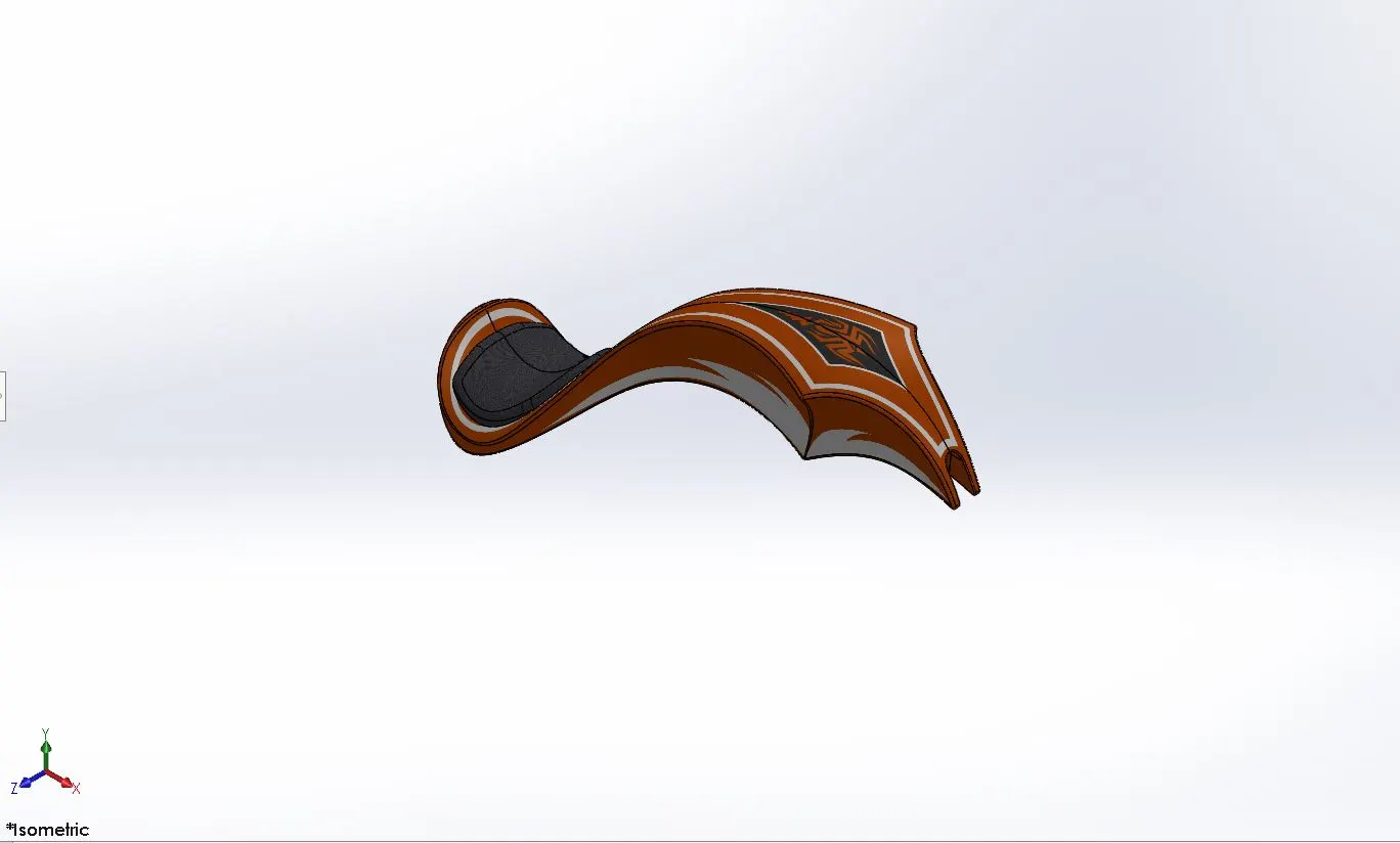
13.Gas Tank
The gas tank is used for the storage of fuel to run power the engine.
Features used to model the Gas Tank:
- Sketch
- Sketch picture
- Project curve
- Reference plane
- Surface sweep
- Surface trim
- Lofted surface
- Boundary surface
- Surface knit
- Surface extrude
- Fillet
- Mirror
- Swept cut
- Shell
- Appearance
DESCRIPTION OF THE TOOLS AND FEATURED USED IN PART MODELLING
1.Sketch
Sketch tools enable the user to sketch the two-dimensional cross-sectional drawing of the part/component. Sketch tool has various entities to achieve the desired shape and dimensions. The entities which are commonly used in Solidworks are Line, Circle, Spline, rectangle, etc
2.Offset
The offset tool helps in creating an offset of the already existing fully defined sketch. The offset may be inward or outward offset depending on the requirements.
3.Boss Extrude
The Boss extrude feature is used for converting the two-dimensional sketches to three dimensional part. The Boss extrude feature allows us to choose the origin point, endpoint, and distance of the part to be extruded.
4.Fillet
The fillet feature is used to smoothen the sharp edges of the extruded part.
5.Lofted Boss
The loft feature is used to create a shape of a varying cross-section along a guide curve.
6.Dome
It applies domes to the circular or elliptical end faces
7.Cut Extrude
This feature allows the user to remove the material from the already extrude part model. The removal of material may be a through-hole or also can be up to certain distances or entities.
8.Split
The Split Line tool is used to project an entity (sketch, solid, surface, face, plane, or surface spline) onto other surfaces or curved/planar faces. This tool is also helpful to cut a part of the extrude model to get the desired shape.
9.Revolved Boss
The revolved boss feature is used to revolve a sketch about an axis or a reference line.
10.Combine
Combine feature is helpful in combing two bodies in part modeling
11.Shell
The shell feature is used for several purposes depending upon the requirements. It can be used to make extrude part hollow, remove a particular face from the part, and provide internal thickness to the body.
12.Sketch Blocks
It is useful in saving the sketch as a separate block and using the same sketch at later stages of part modeling.
13.Pattern
The pattern feature is a handy tool that helps the user to generate multiple bodies and features. The pattern may be a linear pattern, circular pattern, or curve driven pattern.
14.Chamfer
The chamfer is used to make a cut on the edge of the body which makes the edges sloppy rather than being sharp.
15.Move / Copy Body
This feature can be used to move or copy the body within the workspace
16.Reference Plane
This feature creates a new plane and the orientation of the same is done by taking reference to another plane, line, and face, etc.
17.Project Curve
The creation of a 3 D curve with the help of two 2D curves on the different planes can be done with the help of the project curve feature.
18.Composite Curve
This feature combines two curves and makes them into a single curve.
19.Mirror
This feature is generally used in symmetric components where one side of the component is modeled and the other side is mirrored about any reference plane or face. This is a handy feature as it saves a lot of time.
20.Sweep
This feature is used in generating a uniform shape along the curve.
21.Swept Cut
It is similar cut extrude but the material is removed along a curve
22.Revolved Cut
It is similar to cut extrude and swept cut here the material is removed about an axis.
23.Loft surface
Loft surfaces are surfaces generated by multiple 3d curves or existing edges creating a smooth tangency between the selected curves.
24.Sweep surfaces
Sweep surfaces are surfaces that are generated from a section curve positioned along a path
25.Surface Trim
Surface trim is used to cut away the material from the surface
26.Surface Trim
Surface knit is used to knit two edges of the surface together. It nullifies the gap between two surfaces.
27.Surface Extrude
This feature extrudes the surface along a curve or path.
28.Appearance
This tool is used to add appropriate colors to bodies to make it visually more appealing. We can also add decals and scenes.
ASSEMBLY OF THE AMERICAN CHOPPER
- The individual components of an American chopper bike are assembled together to have the full chopper model.
- The process begins by bringing the chassis to the assembly environment and aligning the planes of the chassis with that of the planes in the assembly environment to make sure it is constrained.
- Then all the other parts are opened and made constrained with the by mating the face, planes, and circular cross-section of the chassis to the individual part with the help of the mating feature.
Features used in Assembly of the chopper:
Mates
This feature is used to constraint any two parts by adding a geometric relationship between the two parts. There are many options like tangency, concentric distance, etc to choose from which would constrain one part with respect to another. There are also advance mate options like width mate, Angle mate, etc which would help to add more practicality to the assembled model.
Insert Parts
This feature allows us to add parts needed to assemble in the assembly environment.
Below are images from different views of the assembled chopper
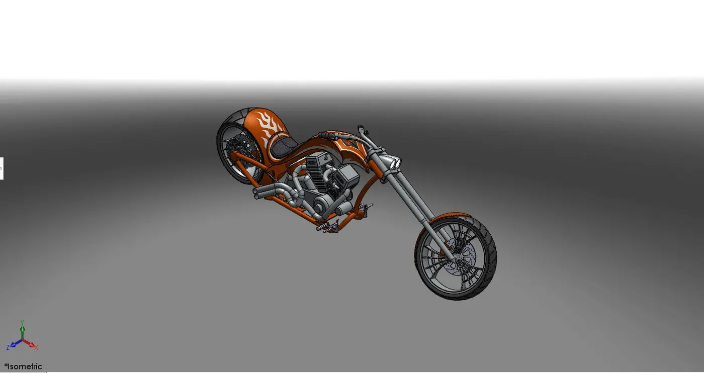
Isometric view of the assembled chopper
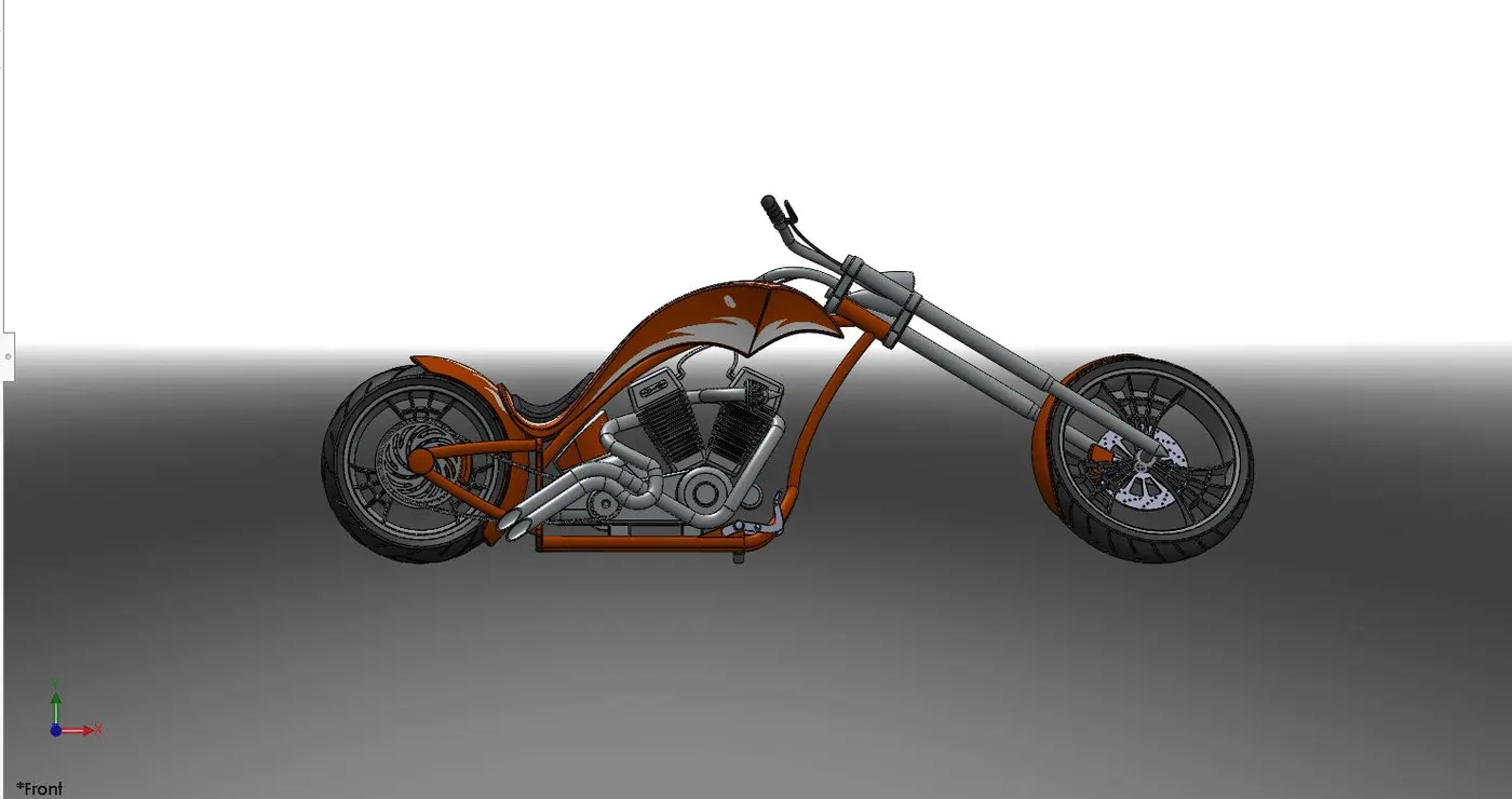
Front View of the assembled chopper
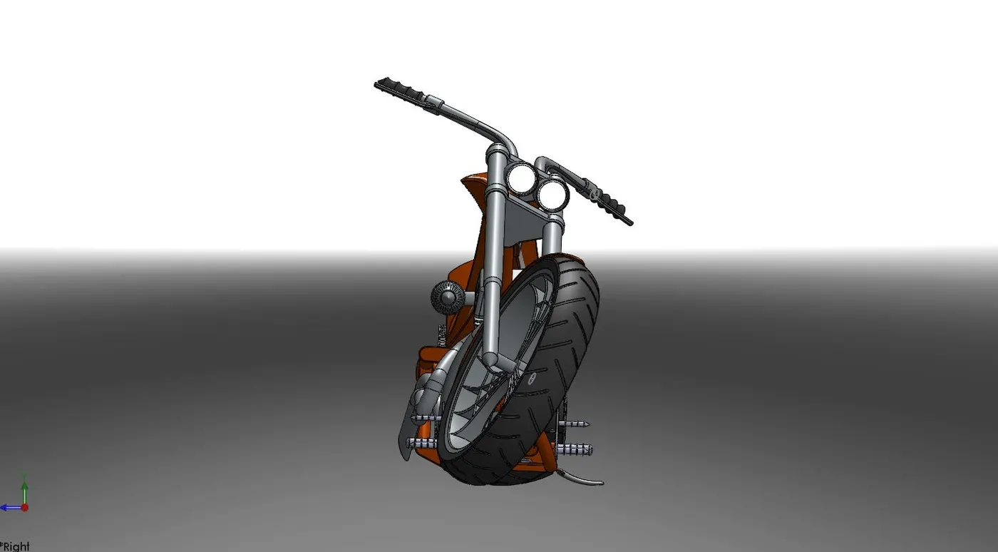
Right side view of the assembled chopper
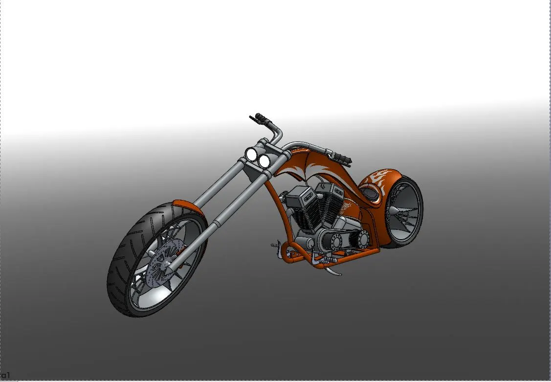
camera view of the assembled chopper
PHOTOREALISTIC RENDERING OF THE AMERICAN CHOPPER
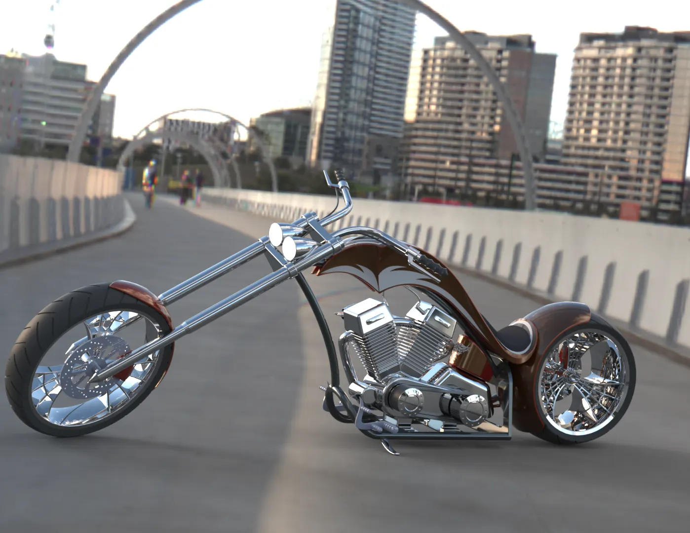
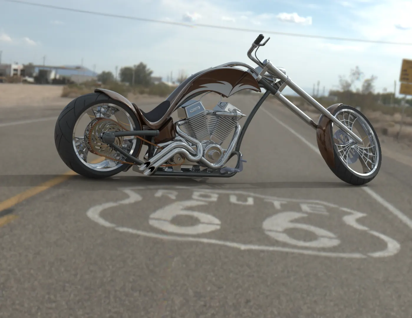
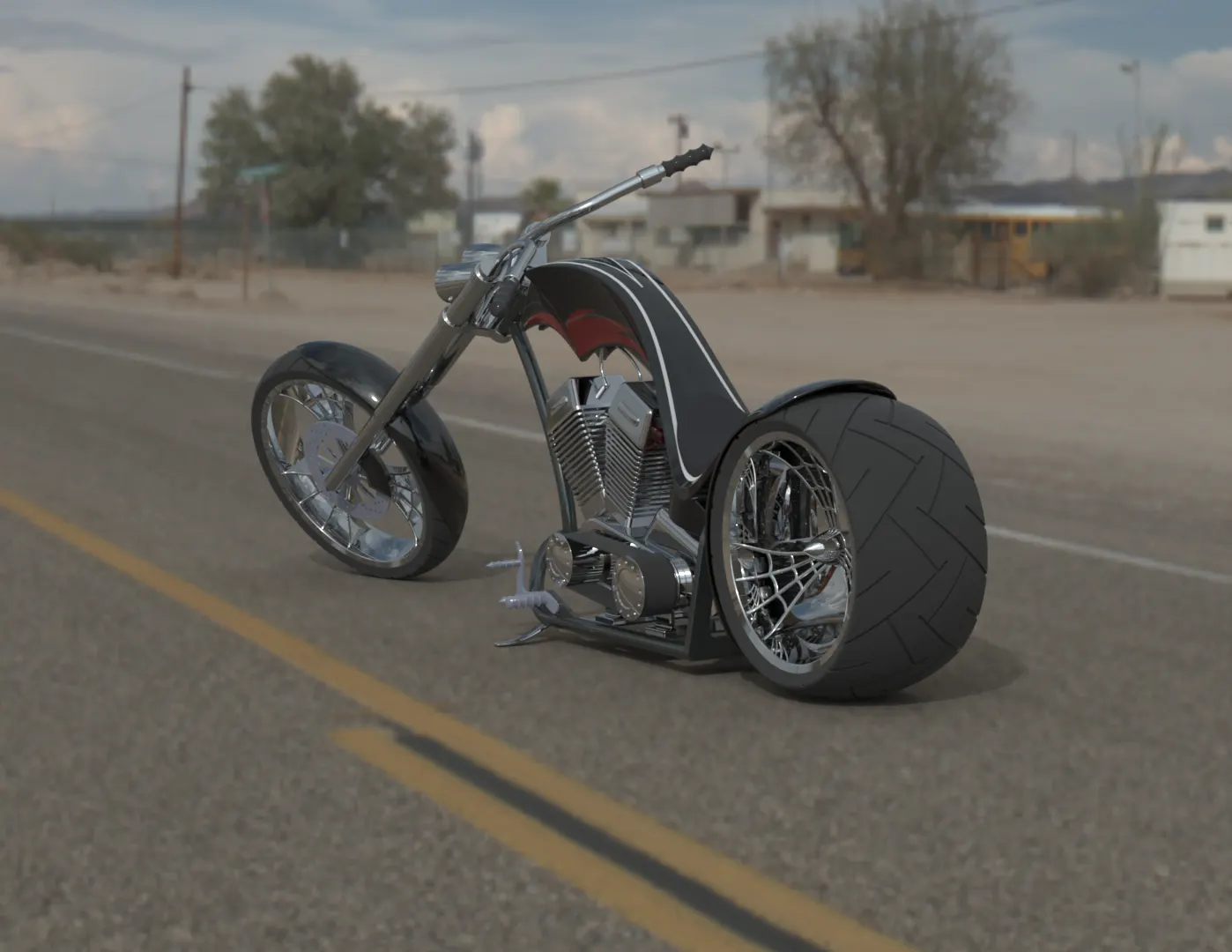
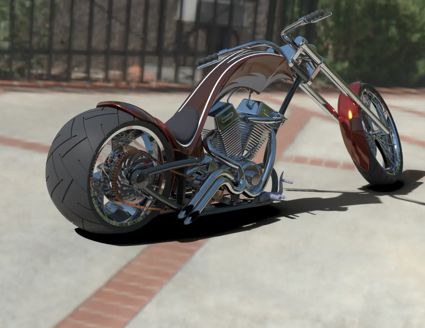
This the final stage of the project where the assembled part is being imported to the Solidworks Visualize. Then the assembled model is made more appealing by changing the colors of each component and is set up in a suitable realistic environment. Finally, rendering is done to the model to get a photorealistic model of the chopper.
Below are the photorealistic images of the American Chopper:
Dockside bridge
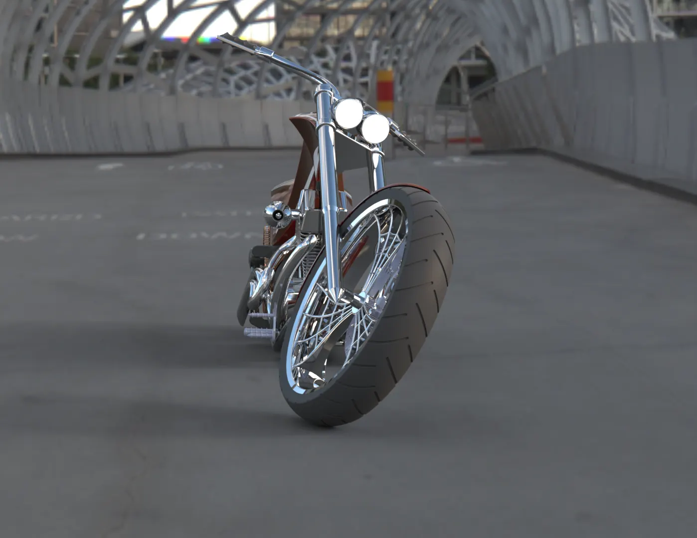
Route 66
Sunny Driveway
CONCLUSION
The components of the American Chopper bike are modeled and assembled together in the assembly environment.
The photorealistic rendering of the assembled model was done with Solidworks Visualize.