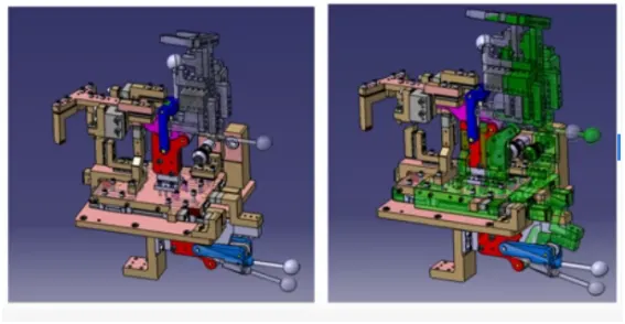
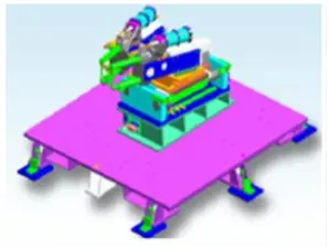
Week 3:- BiW Fixture Design Methodologies Challenges
1.What is design Methodology?
Design methodologies are the steps that are followed during the concept designing stage of the fixture.
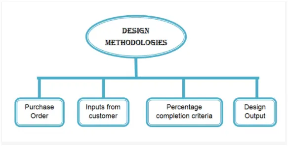
1.Purchase Order(PO)
- The purchase order (PO) is the official document received from the customer. which commits the customer to pay the seller for the sale of a specific product to be delivered in the future.
- Once the seller receives the PO then they can start working on the project
- Purchase orders enable customers to clarify their exact needs to the Seller. Not only does this help ensure that you get off on the right foot, but both parties can use it as a formal check-in case orders are not delivered as expected.
2.Inputs from the customer
During the designing process, we get the inputs from the customer.
The inputs that we get from the customer are as follows:
- Functional Requirement
The inputs regarding the functional requirement of the fixture are received from the customer like for which process the fixture needs to be designed. For example, welding fixture, gluing fixture, Checking fixture Etc.
- Preferred Standards
It is important to consider the standards which are maintained by the customer. The usage of standard parts during designing will simplify the designing process as we could take the references from them implement it in our design, which eventually reduces a lot of time and cost of the projects. Standard parts like riser, L –Blocks, pins, and components like cylinders can be used during design.
- Car Products
The inputs regarding GD&T, part lists, Clamp plan, Pin Locating Points, Product assembly Process Sheet are received by car products.
- Layout
The layout provides information about the flow of product, assembly sequence, the position of robots, etc.
- Ergo data
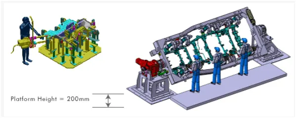
Ergonomics defines as the study of human behavior and movements. The ergo data like the height, distance from the fixture is given as an input by the customer and the design of the fixture must adhere to these data. This design will result in ease of operation for the operator of the fixture.
- Weld Study
Weld study gives information about the type of weld gun to be used for the process. Also, it gives information about the number of geo weld spots as well as the number of Re-spot welds.
3.Percentage of completion criteria
It is used in the design and dispatch stages of the welding fixture. It shows the number of tasks completed in the project.
Different stages in a project have a different percentage as follows
- Input and concept design 0-25%
- Concept approval and Simulation check 25-40%
- Design Freezing and detailing 40-80%
- Check and Final Dispatch 80-100%
4.Design Output
The output is 3D models and 2D drawings of the tools. The Unitized tools require both Key sheets and layout sheets whereas the non-unitized tools require only Layout sheets.
2.What are the inputs required from the customer to start designing a Fixture?
The inputs that we get from the customer to start the designing of the fixture are as follows
- Functional Requirement
The inputs regarding the functional requirement of the fixture are received from the customer like for which process the fixture needs to be designed. For example, welding fixture, gluing fixture, Checking fixture Etc.
- Preferred Standards
The customer wants to follow some standards. These standard parts should be used in our design which saves time and money spent on the project.
ABB , NAAMS , Tunkers are some standards
Some components like Clamps, Cylinders, switches, etc are used based on the preferred standards of the company.
Car Products
The inputs regarding GD&T, part lists, Clamp plan, Pin Locating Points, Product assembly Process Sheet are received by car products.
GD & T
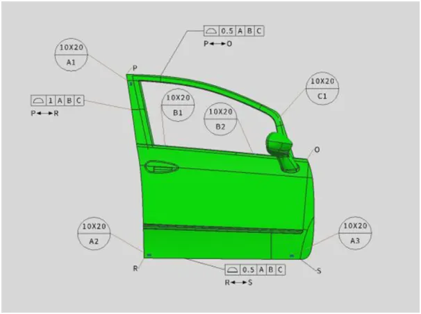
It gives information about the location of pins, Rest, clamps, and slide unit information of each station.
Parts lists
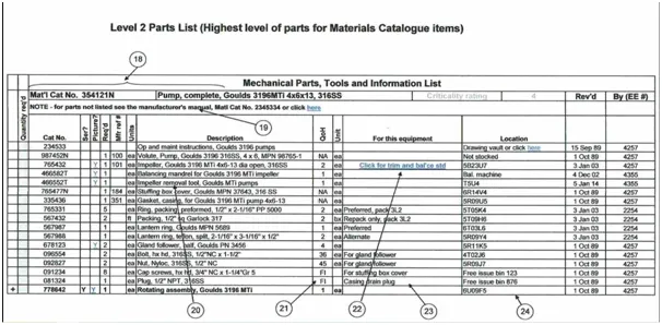
It gives information of part like part name, the part number of the part which is to be assembled in the fixture.
Clamp Plan
Clamp plans give the location of pins, rests, clamp, dumps, etc. we need to consult with the customer if we need to make changes in the clamp plan.
Product Assembly process sheet
It gives details about the sequence of the assembly of parts in the various stations.
CAD Files
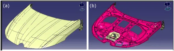
The 3D model of the car part is required for designing the fixture for that particular part.
Layout
The layout provides information about the flow of the product, assembly sequence, the position of robots, sub-assembly links, accessories like tool changer and tip dresser, platform height.
Ergo data
- Ergonomics defines as the study of human behavior and movements.
- The ergo data like the height, distance from the fixture is given as an input by the customer and the design of the fixture must adhere to these data.
- This design will result in ease of operation for the operator of the fixture.
- Weld Study
Weld study gives information about the type of weld gun to be used for the process. Also, it gives information about the number of geo weld spots as well as the number of Re-spot welds. These spots will be indicated using red and green spheres respectively.
3.What are the inputs we get from "Car Products"?
The inputs that we get from the care products are as follows:
- GD&T
- Part Lists
- CAD Files
- Clamp Plan
- Product Assembly Process Sheet.
- GD&T
The input about the geometric dimensioning and tolerance of the part for which the fixture is being designed.
The GD&T provides information about the location of the pins and Clamps which are the major units in a fixture to hold the part that needs to be processed.
- Part Lists
It gives the lists of parts that are going to be assembled in the fixture.
The part lists contain information about the part number, part name, part thickness, etc.
- 3D CAD FILES
The 3D Cad files will be provided from the customer end of the part for which the fixture needs to be designed.
- Clamp Plan
Clamp plans give the location of pins, rests, clamp, dumps, etc. we need to consult with the customer if we need to make changes in the clamp plan.
- Product assembly process sheet
It shows how the product is going to move from one assembly station to another and also provides information about which part to be assembled at which stage.
No changes can be made in the assembly process without consultation with the customer.
4.What is the Clamp plan?
A Clamp is a device that is used to hold the part tightly, yet, firmly in the assembly, The clamp prevents any sought of movement of the assembly in the fixture and ensures proper operation on the part without any distortion.
The clamp must be placed in such a way that it does not interpret the operation.
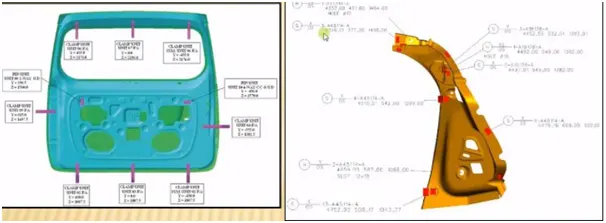
The clamp plan is the data provided by the customer. The clamp plan provides information on the location of pins, rest units, Clamp units, Dumps, etc.
It gives the details of the exact position of the clamping locations in form of coordinates
The clamp position in some cases will be in such a way that it might damage the tool, or very near to pin position. In such cases, We should not take the decision to change the clamp plan without discussing it with the customer.
5.What is the purpose of a Layout?
The primary objective of a layout is to demark the entire shop floor area as per the tasks which are done there.
The layout provides information about the flow of the product, assembly sequence, the position of robots, sub-assembly links, accessories like tool changer and tip dresser, platform height.
- The flow of the part tells the information about how the part is going to move from one station to another.
- The Station pitch tells information about the space constraints between two robots.
- The robot station is the location of the robot.
- The position of Tip dressers and tool changers is important so that the robot drops one tool at that position and takes another tool.
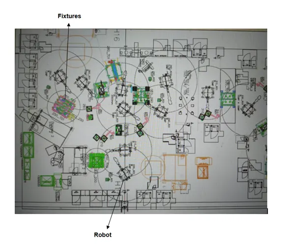
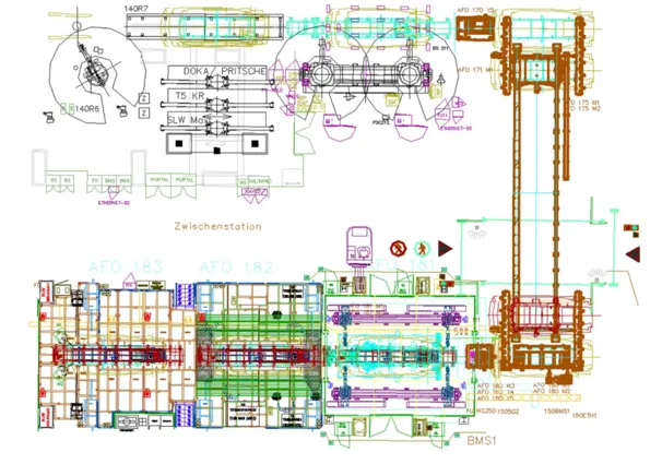
The above image shows the layout of an assembly plan
- The layout clearly shows the positions of the robot and the fixtures
- The circle which is drawn around a robot depicts the swept area of that particular robot.
- The swept area is the reachability of that particular robot and the placement of the fixture must be within the swept area.
- The Details of the fixtures like geo fixtures are mentioned in the layout.
- Any changes made in the layout must be discussed with the customer.
6.What is Ergo data?
Ergonomics is the science of refining the design of products to optimize them for human use. Human characteristics, such as height, weight, and proportions are considered, as well as information about human hearing, sight, temperature preferences, and so on. Ergonomics is sometimes known as human factor engineering.
- The ergo data like the height, distance from the fixture is given as an input by the customer and the design of the fixture must adhere to these data.
- This design will result in ease of operation for the operator of the fixture.
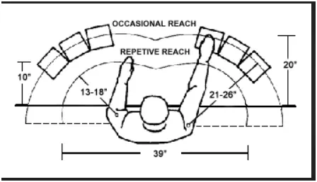
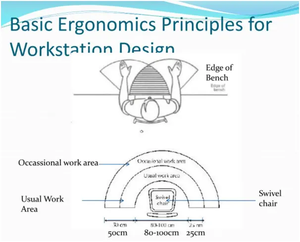
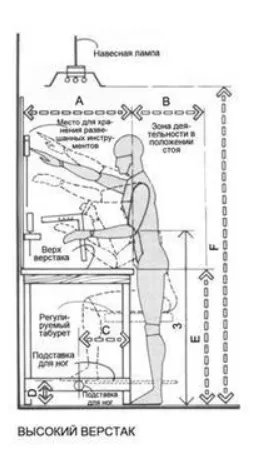
In the automobile industry, for example, if an operator is working on fixture loading and unloading the assembly and he does the same process for 8 hours a day. So, the fixture should be designed based on the ergo data provided by the customer. If these fixtures are poorly designed or improperly adjusted for human use, the person operating them may suffer unnecessary fatigue, stress, and even injury.
7.What do you understand from the Weld study?
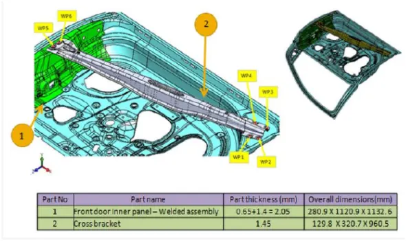
- Weld study is important information collected from the customer. The Weld study gives information about the Weld gun, Weld matrix, and weld points.
- The weld point is the points the weld is going to happen.
- The weld points are very important data and changing those points would result in the improper assembly of the part in the Fixture.
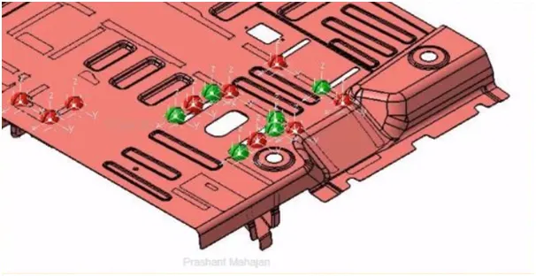
- Also, it gives information about the number of geo weld spots as well as the number of Re-spot welds.
- These spots will be indicated using red and green spheres respectively.
- Geo Weld points are those which are welded in a geo fixture. These points are important as they make sure the assembly is not distorted while taking to a respot fixture.
- The respot weld is done after the geo weld. These welds add strength to the assembly before it is being married with other panels
- Weld study is important in the automotive industry as the BIW of any car will minimum have at least 5000 weld spots.
8.What are the criteria for percentage completion in the designing stage? Explain it in detail
It is used in the design and dispatch stages of the welding fixture. It shows the number of tasks completed in the project and we can make sure whether the work is being done as per the planned schedule.
Different stages in a project have a different percentage as follows
- Input and concept design 0-25%
- Concept approval and Simulation check 25-40%
- Design Freezing and detailing 40-80%
- Check and Final Dispatch 80-100%
- Input and concept design 0-25%
It is the initial stage of the project where we get all the design inputs from the customer and based on those inputs a design concept of the project will be created.
- Concept approval and Simulation check 25-40%
Once the concept is designed it is sent to the customer for approval and the simulation checks are done for the given design and looked for the feasibility of the design.
- Design Freezing and detailing 40-80%
The changes are done to the design if the results of the simulation checks force us to do or if there any changes suggested by the customer. After all these changes are done the design is fixed and the detailing to the design starts
- Check and Final Dispatch 80-100%
After the detailing, it is sent for the quality inspection and finally dispatched to the customer.
9.Brief about "Output" in design?
- The output is 3D models and 2D drawings of the tool.
- The output tools are of two types
- Unitised tools
- Non-unitized tools
Unitised Tools
- The tools which are mounted in a common base like the pin unit, clamp unit, rest unit are all called unitized tools.
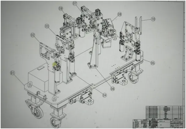
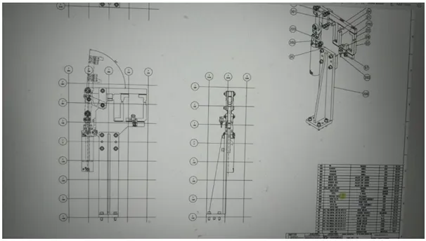
- These tools require two types of drawing sheets namely Key sheets and layout sheets.
Key sheet
It provides information about the Index of units and their placement on the tool base.
Layout Sheet
It is the detailed drawing of individual units to include all their components.
Non-unitized Tools
- Nonunitised tools are stand-alone tools like gluing stand etc
- They need only a layout sheet and can be detailed solely on it
The design output should compile the following points
- Approved standard parts should be used wherever possible
- The design should be simple and economical
- The design must comply with all safety and ergo standards
- Motion control must be considered on any moving component.
- The weight of the moving part must be kept minimum while not compromising the strength
- Controlled and damage-free handling of the parts.
- The designer is responsible to validate all the clamps and weld guns.
- Frames and structures must be simple and sturdy.
10.What do you understand by structuring a design tree? How does it reduce errors during the design process?
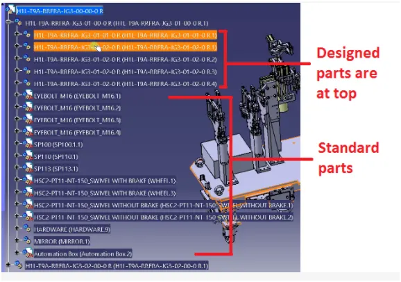
- Structuring a design tree implies a process where all the assemblies and parts are named in a specific standard. Every customer will have their own set of standards to structure the design tree.
- It is an important process that helps us to identify the specific part or assembly as to which project, tool/unit it belongs to.
- This helps us to avoid errors during design study, manufacturing, assembly, inspection.
- If the parts are the assemblies are not named properly or the design tree is not structured properly, it will create confusion to understand the design and may create major possibilities of making an error.
- The naming of a fixture or a unit or a part gives the information as to which project, tool or unit, it belongs to
- It can help us identify the number of items of the same type or different type that are being used in an assembly.
- Two or more components which have similar design are given the same name such that one component is taken as a reference during manufacturing.
- In a design tree, the parts which are designed by us should be placed in the top.
- The standard parts which are used by the customer must be placed below the list of the designed part, by not placing the standard parts in the design tree would be led to manufacturing these parts again and would take up both money and time spent on the project.
- The other standard parts or parts that are procured from outside must be placed in the bottom of the design tree like the fasteners, cylinders, etc.
- What are Units? Mention 5 types of units.
- The fixture is the assembly of different units. Some of the units used in fixture assembly are the Base unit, Pin unit, Clamp unit, etc.
- Unit is used to perform a specific function in the fixture.
- Units are part of the unitized tool.
- Units are of two types as follows
- Simple unit
- Complex unit
Simple unit
The simple unit as the name suggests has a simple design, the design process and manufacturing is also simple.
The simple units are further classified as below:
- Rest unit
- Fixed pin unit
- Retract pin unit
- Rough locator unit
- Sensor unit
- Base unit
Complex Unit
As opposed to the simple unit, the complex unit has a complex design process and manufacturing process.
They are classified as follows
- Slide unit.
- Dump unit.
1.Rest Unit
- Rest unit is the unit on which the components are rested.
- There is no upper clamping and no force is applied.
- Rest units generally have a riser, blade, and rest Mylar.
2.Base Unit
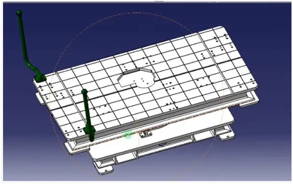
The base unit is the unit that is used to mount all the other units like clamping unit, rest unit, pin unit, etc, other parts like automation box are also mounted on a base unit.
3.Fixed Pin Unit
Fixed pins are the non movable fixed pins that are used to locate the part in the fixture.
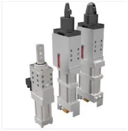
4.Retractable pin unit
- Retractable pin unit is opposite to fixed unit which can be moved up and down up to the certain distance.
- It is used for unloading complex panels after welding.
5.Slide unit
- Sliding units are used in a fixture when there are a lot of space constraints, where usage of different units is very difficult in order to design the assembly.
- Describe Fixed Pin units & their purpose?
- Fixed pin units are used in a fixture to locate the car panel during any operation.
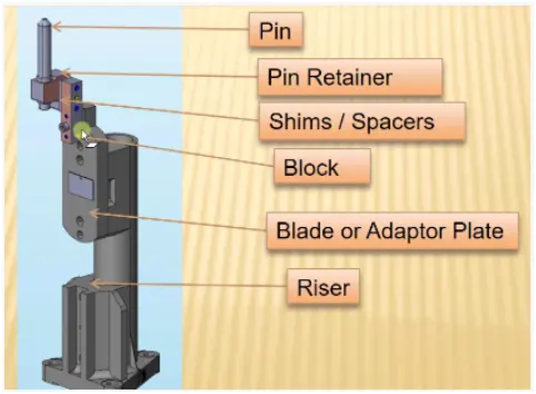
- Pin, Pin retainer, Shims, blade, riser are the parts of the fixed pin unit.
- Pin retainer is used to mount the pin.
- The pin retainer block has two-way shims. Shims are very important in designing a pin unit as it helps to avoid the stack up tolerances during the assembly process.
The purpose of the Fixed pin unit.
- The fixed pin unit is used to arrest the 6 degrees of freedom of the assembly of a fixture. The other six degrees of freedom are arrested by the three rest units.
- Pins help to locate the part of an assembly very accurately for the welding operation.
- What are the different parts of a fixed unit?
The different parts of a fixed pin unit are as follows
- Pin
- Pin Retainer
- Shims
- Blade
- Riser
Pin
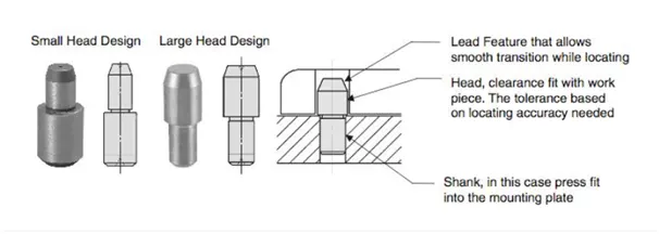
- Pins are used for accurately locating the part to welded in an assembly.
- The holes in the part of the assembly are inserted on these pins.
- The pins constrain the degrees of freedom of the part of the fixture.
- The diameter of the pins has tighter tolerances as compared to the diameter of the hole in the part.
Pin Retainer
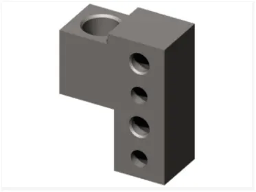
Pin retainer is used to hold the locating pins. The pin retainer block has two-way shims.
Shims
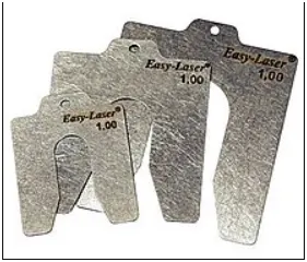
Shims are small parts of the thickness of 0.1,0.2,0.3 mm. The shims are used to compensate for the difference due to the stack-up tolerance of the assembly, which eventually results in the improper holding of the panel if the Mylar holds it loosely. On the other hand, if the Mylar holds the panel very tightly then it will form an impression in the panel. Shims play a major role by adjusting the Mylar to the defined position.
Blade
- Blades are plates that are attached to the raiser.
- The cylinders and other additional arms are mounted on a Blade.
Raiser
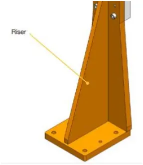
- A raiser is a part that is used to raise the height of the fixture.
- The raiser is fixed to the base of the fixture and the blade is mounted on the raiser
- There are two types of raisers 1.L type raiser 2.Square Tube raisers.
14.What is the purpose of making a Rest unit & describe its parts?
- The rest units are designed to support the car panels using Mylar.
- The primary purpose of the Rest unit is to rest the car panel.
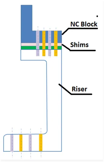
- The parts of the rest units are as follows
- Mylar
- Blade
- Riser
Mylar
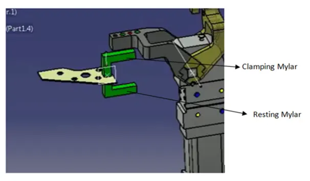
- Mylar is the part that holds the panel from above and below during the operation.
- The top side of Mylar is called the clamping Mylar. Whereas, the bottom side Mylar is known as resting Mylar.
- Every Clamping Mylar will have a resting Mylar.
- It holds the panel in such a way that it does not deform during the welding process.
- The below image shows basic Clamping and Resting Mylar.
Raiser
- A raiser is a part that is used to raise the height of the fixture.
- The raiser is fixed to the base of the fixture and the blade is mounted on the raiser
- There are two types of raisers 1.L type raiser 2.Square Tube raisers.
Blade
- Blades are plates that are attached to the raiser.
- The cylinders and other additional arms are mounted on a Blade.
- What are the basic fundamentals to design a Sensor unit?
- A sensor unit is used to sense whether the car panel is placed in the fixture or not.
- The sensors will send the signals to PLC systems and so the next process will be executed by this signal.
- The number of sensors used in a fixture will depend upon the number of parts used for the assembly.
- Every panel should by one or two panels depending on the size of the part and in such case they are placed in the opposite direction.
- The mounting of the sensors should be in such a way that they are adjustable in three directions.
- Some of the major sensor manufacturers are IFM, SICK, OMRON, etc
The types of sensors used are as follows
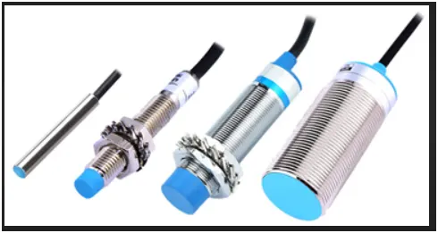
- Proximity Sensor.
- The proximity sensor is a sensor able to detect the presence of nearby objects without any physical contact.
- A proximity sensor often emits an electromagnetic field or a beam of electromagnetic radiation (infrared, for instance), and looks for changes in the field or return signal.
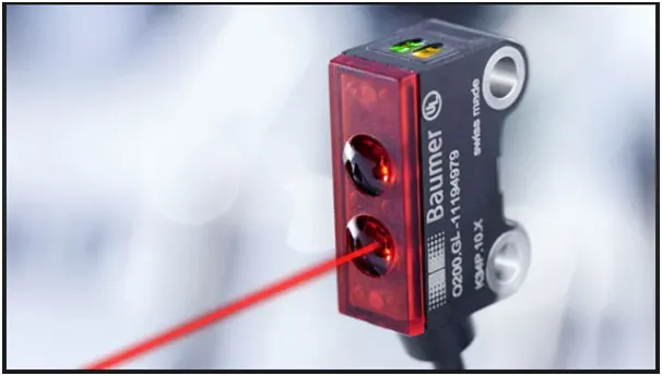
LASER sensor
- A laser sensor is a kind of sensor that uses laser technology to measure. It is generally composed of laser, optical parts, and photoelectric devices.
- It can convert the measured physical parameters (such as length, flow, speed, etc.) into optical signals, and then use a photoelectric converter to convert the optical signals into electrical signals.
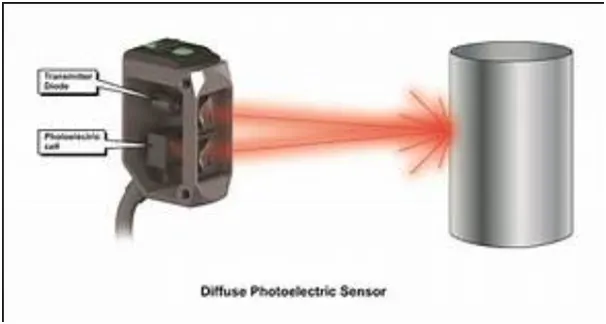
Photoelectric Sensors
- Photoelectric sensors are made up of a light source (LED), a receiver (phototransistor), a signal converter, and an amplifier.
- The phototransistor analyzes incoming light, verifies that it is from the LED, and appropriately triggers an output.
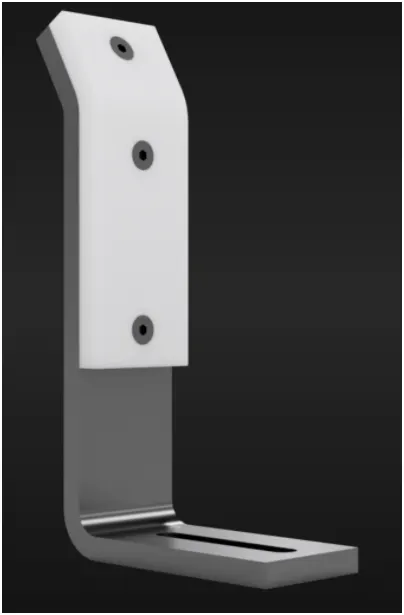
- What is a Rough locator unit & what are the basic fundamentals to consider while designing it?
- Rough locators are majorly used in manual fixtures.
- The rough locators will guide the operators to place the part in the correct position and orientation.
- The rough locator can be a standard part or make part.
The fundamentals of rough locators are as follows
- Rough locators have to be placed at the edge of the car panel in order to guide them.
- There must a gap of 2-5 mm between the rough locator and the car panel in order to avoid damage during loading and unloading.
- Rough locators have to be placed at the same angle as the car panel.
- Rough locators should guide the panel in pin arresting direction.
- Rough locators should start guiding the panels 10-15mm before the pin engagement
- Rough locators should be designed with an entry angle for the car panel which is around 35-40 degrees.
- Rough locators should be designed with two slots to mount for easy adjustments.
- The slots should be in direction of the car part guiding.
17.What is a Base unit and describe its parts?
The base unit is designed to mount all the other units like clamp unit, pin unit, rest unit, etc of the tool, also other parts like pneumatic valve box, trunking cable path will also be mounted on the base unit.
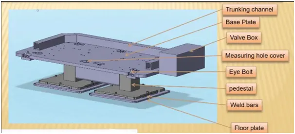
The parts of the base unit are as follows:
- Valve box
- Trunking Channel
- Measuring hole cover
- Eyebolt
- Pedestal
- Floorplates
Valve box
- A valve box is used to supply pneumatic cylinders assembled in the fixture.
- The valve box consists of solenoid valves with an inlet and outlet which controls the supply of air to the cylinder.
Truncking channel
Trunking channel is a hollow passage that guides and covers the pneumatic and electrical linings.
Measuring hole cover
The measuring hole cover the coordinates of the measuring holes are mentioned. These coordinates are used as references for placing the other units and also for the CMM inspection purposes.
Eyebolts
Eyebolts are placed in the base unit in order to lift the base unit and move it from one place to another.
Pedestal
The pedestal is a stand-like structure where the entire unit of the base will be mounted.
Floorplates
Floorplates are used to mount the entire base on the floor.
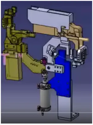
- What is a Dump Unit and what are its functions?
- Dump unit is found in complex fixture
- A dump unit is used when there are geometrical constraints while placing a panel.
- It consists of a dump cylinder to perform clamping and unclamping operation.
- What is a Slide unit? Mention where Slide units are commonly used
- Sliding units are used in a fixture when there are a lot of space constraints, where usage of different units is very difficult in order to design the assembly.
- The sliding unit consists of a sliding cylinder to which a panel is attached
- The panel moves on the guide rails provided and this motion is due to the reciprocating motion of the cylinder
- The position locking units are used to lock the position of the panels on the guide rails
- Sensor units are used to detect the position of the sliding plate, whether it has reached the desired position or not.
- A stopper block is used to control the motion of the sliding plate.