Advanced Sheet Metal Design Using NX Cad Challenge_5_Odd Shaped Enclosure
ADVANCED SHEET METAL DESIGN USING NXCAD – ODD SHAPED ENCLOSURE
OBJECTIVE
To design an Odd shaped enclosure using NX sheet metal application.
INTRODUCTION
Sheet metals are thin, flat pieces of metal that are formed by various industrial processes. Typical sheet-metal thicknesses are between 0.4 mm (1/64 in) and 6 mm(1/4 in). When thickness exceeds about 6 mm, the stock is usually referred to as a plate rather than a sheet. The sheet or plate stock used in sheet metalworking is produced by flat Rolling. The most commonly used sheet metal is low carbon steel (0.06%–0.15% C typical). Sheet metal is characterized by a high ratio of surface area to thickness. Sheet metals are widely used in the automobile, aerospace, and piping industries.
Siemens NX software is used for sheet metal design. NX sheet metal provides a good set of tools in order to design the sheet metal part while the manufacturability of the sheet metal is also considered.
DESIGN METHODOLOGY
STEP 1
Create a sketch profile in the XZ plane with given dimensions.
STEP 2
Create an extrude of 200mm using the above profile.
STEP 3
Wrap the sheet metal around the solid body by selecting suitable faces and bend edges using Sheet metal from solid Feature.
STEP 4
Create a flange on one of the sides of the model.
STEP 5
Similarly, Create a jog on the opposite side of the model.
STEP 6
Unbend the model to add more features
STEP 7
Create a circular bead of 3mm radius by selecting a suitable face and sketch
STEP 8
Create holes of 10mm diameter as per requirements.
STEP 9
Rebend the unbend areas.
STEP 10
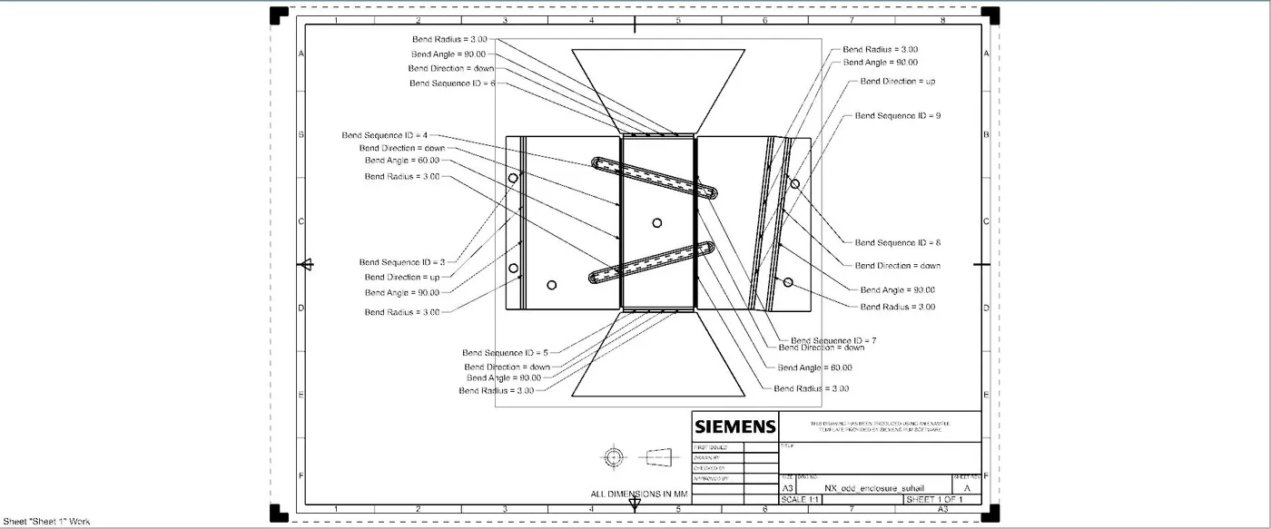
Create a flat pattern with necessary labeling
STEP 11
Using the flat pattern create a draft.
DESCRIPTION
1.Sketch
Sketch tools enable the user to sketch the two-dimensional cross-sectional drawing of the part/component.
2.Extrude
It creates a solid body of the sketch profile.
3.Sheet metal from solid
It creates a sheet metal body from the solid body by wrapping the sheet metal around the faces of the solid body.
4.Flange
Adds a flange at an angle to the planar face and creates a bend between the two it gets extended from the edge of the sheet metal.
5.Unbend
Unbend feature is used to flatten the bends and flanges created with respect to the stationary face.
6.Rebend
This feature unbends the materials to its previous bent state.
7.Bead
Lifts material along the contour of the sketch that simulates a stamping tool.
8.Holes
This feature adds holes in the model as per requirements at the appropriate positions. The diameter and type of hole could also be selected as required
9.Flat pattern
It creates a flat pattern of the sheet metal part
IMAGES OF THE MODEL
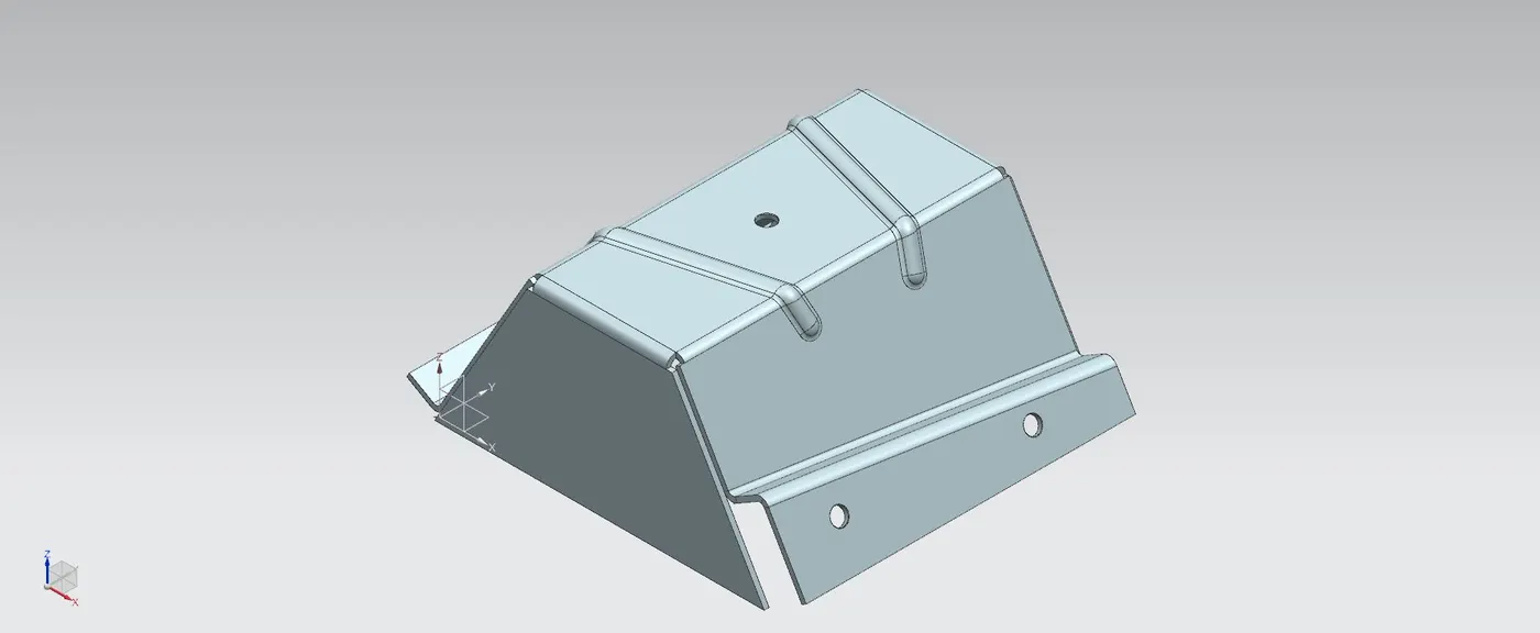
Isometric View
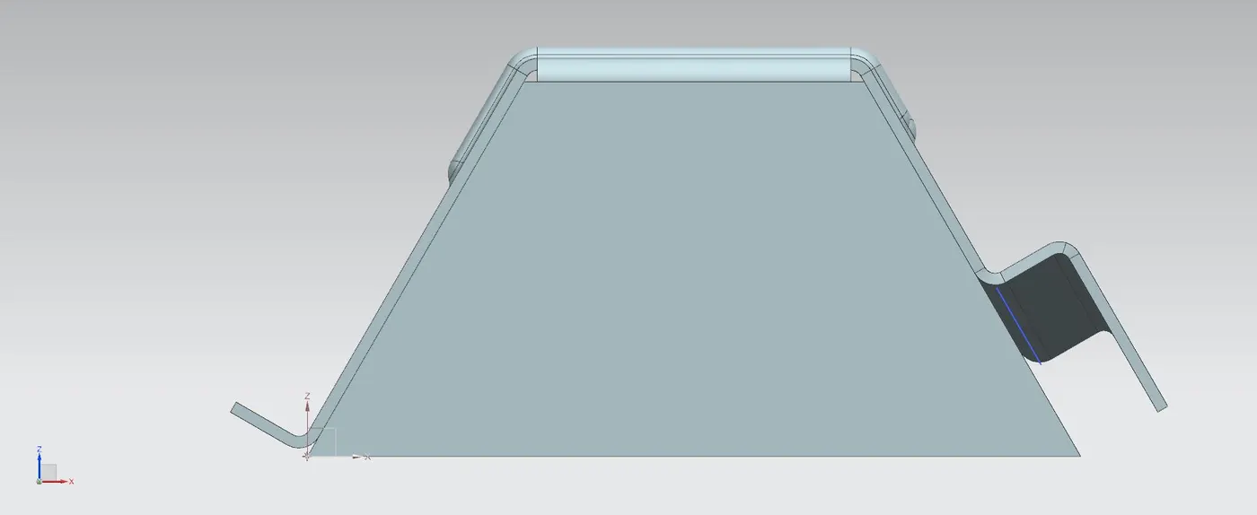
Front view
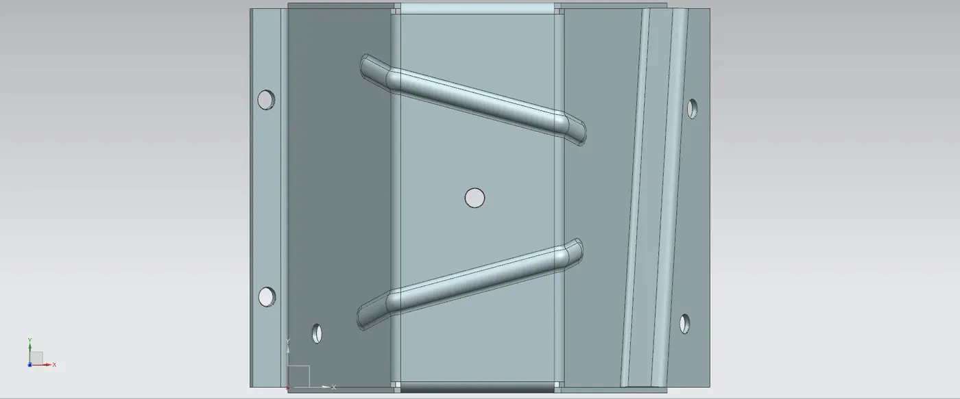
Top view
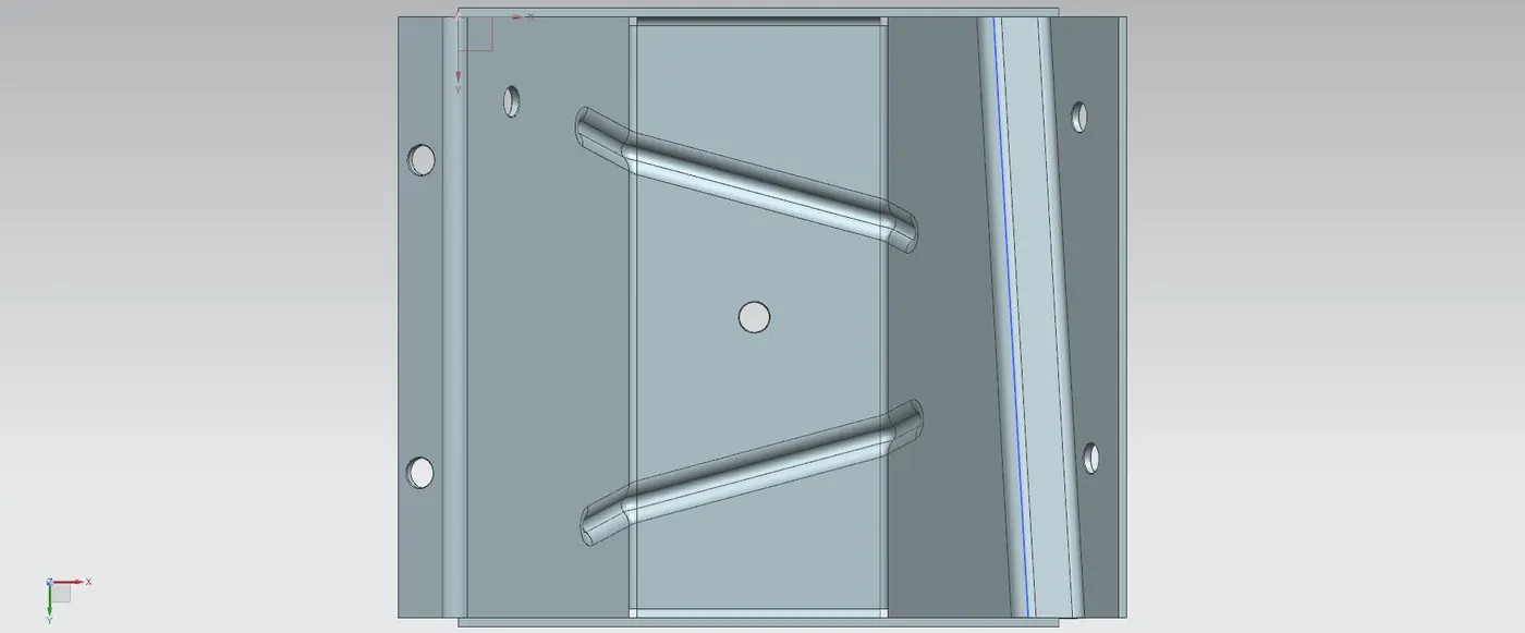
Bottom view
DRAWING SHEET
CONCLUSION
The odd-shaped enclosure was Created using the NX Sheet metal application.