Week 8:- 3D Finishing - Challenges 1
1.What do you understand by the 3D finish process?
- 3D Finishing is a process where the design is being completely and to be ready for final simulation and 2D detailing
- During the design finishing process, the nominality of the design is checked to have the easy assembly of the units.
- The hole concentricity and hole sizes are checked for proper assembly of all the units.
- The gaps between the different units are checked to ensure proper working of the individual units.
- The rough locators are designed which helps in loading the panel's incorrect orientation.
- The pneumatic layout is designed for pneumatic connections to various cylinders.
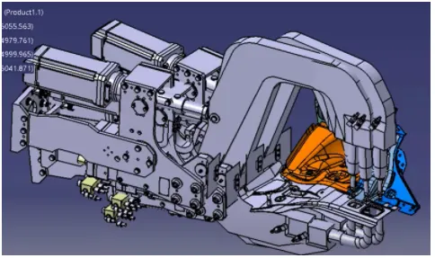
- Gun study is done during 3d finishing to ensure the proper welding of the panel.
- Selection of Sensors, solenoid valves as per the requirement and implementation in design.
- Renaming of the assembly and the part is done to give every part a different identity for easy identification of each part in the assembly
- Fasteners are added to the units as per the requirements
- Finally, the model is sent to the simulation and 2D finishing is done.
2.What are the points that need to be taken care of while finishing the design?
Hole concentricity and the hole sizes
Hole concentricity is checked and confirmed for all the parts in a unit for easy assembly while finishing the parts.
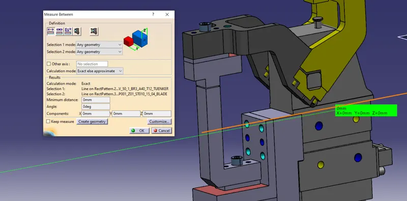
Machining Area
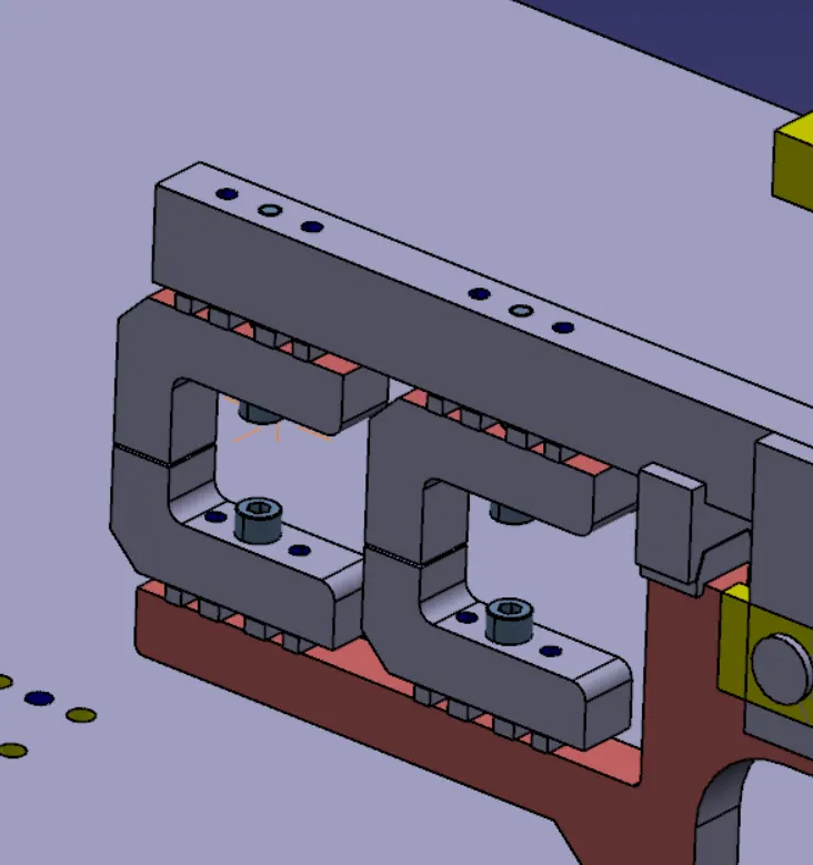
The machining area in every part should be designed and the machining area should be highlighted using standard color. The below image shows the machining area highlighted.
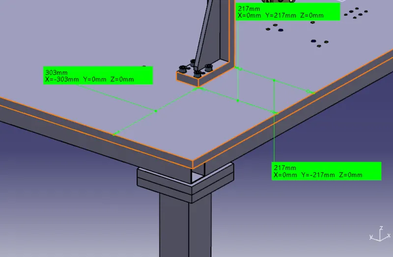
Nominality
All unit's dimensions should have nominal values to facilitate easy assembly of the unit. The below image shows the unit being placed with nominal distance and the same has been done for every other unit in the fixture assembly.
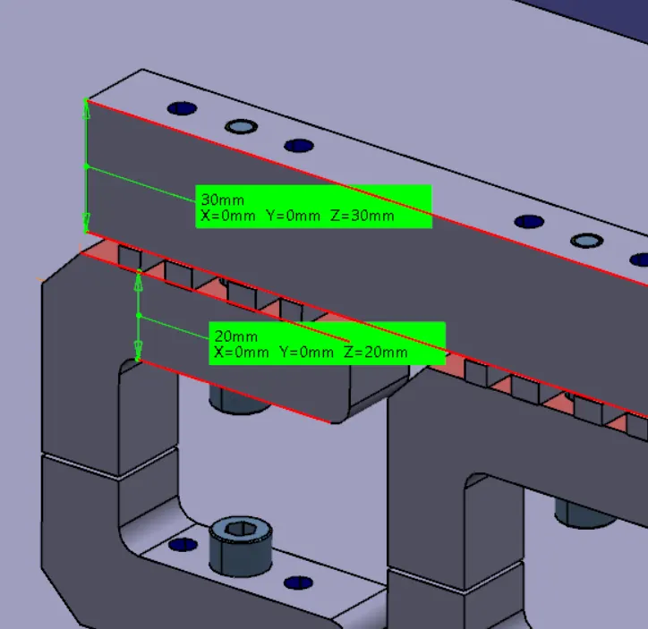
The dimensions of every part of each unit are also given nominal values so that it becomes easy to manufacture and assemble.
Holes colouring standard
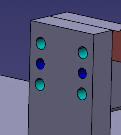
In a 3D finishing process, hole colouring should be done in order to identify the type of holes. The dowel hole is given Blue colour, Threaded Hole should be coloured with yellow and the counterbore, the open hole should be given Cyan blue colour.

Pneumatic Lay outing
The pneumatic lay outing is a collection of different pneumatic pipes which gives compressed air to the cylinders. The lay-outing must be proper to have the proper working of the units.
Gaps Checking
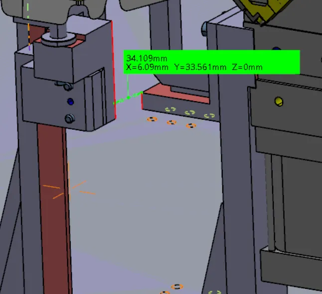
A proper gap of at least 5mm should be maintained between different units to avoid the clash between them.
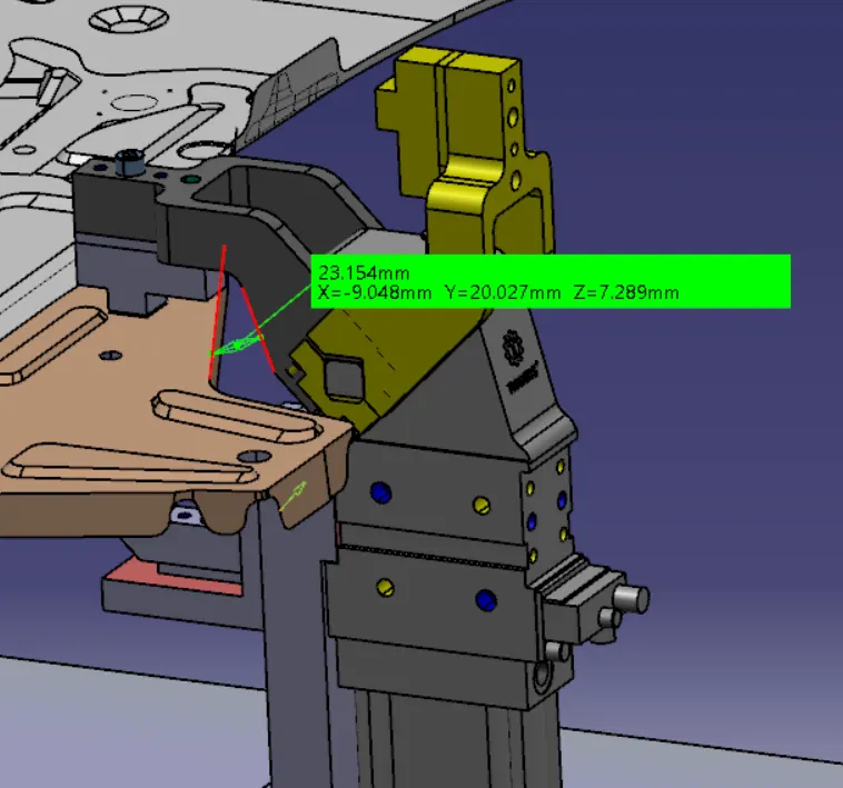
The above image shows the gap between the unit and the panel. Similarly, the gap between different units is also measured.
Fasteners implementation
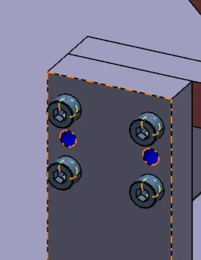
Fasteners should be implemented in all the units as per the requirement.
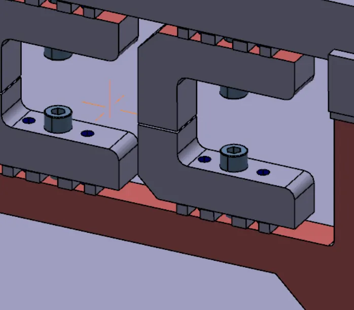
Mylar Splitting as per panel profile
Mylar Splitting should be confirmed while the design finishing the design. The thickness of the panel should be taken into account while splitting the panel.
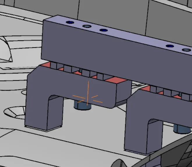
The above image shows the clamp mylar splitting the panel profile with a thickness of 1mm.
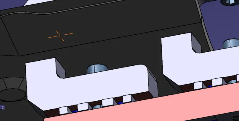
Splitting of the panel bottom profile with rest mylar.
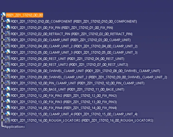
Proper renaming of parts as per the standard
Proper renaming of the parts and products in the specification tree is important so that it will be easily identifiable.
3.What are rough Locators & what is their use?
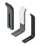
- Rough locators are basically used where manual loading of panels are to implemented on the fixture
- These are used to guide the panels in the correct position and orientation.
- These also help for proper poka-yoke
- Materials used for rough locators are Mild steel and similar metals.
- The accuracy of the locating components directly affects the consistency and how the final product will come out.
- It can be called a foolproofing method.
- Foolproofing is a method by which ensures that the workpiece will fit into the fixture only if it is placed in the correct position.
4.What are the points you need to consider while designing a rough locator?
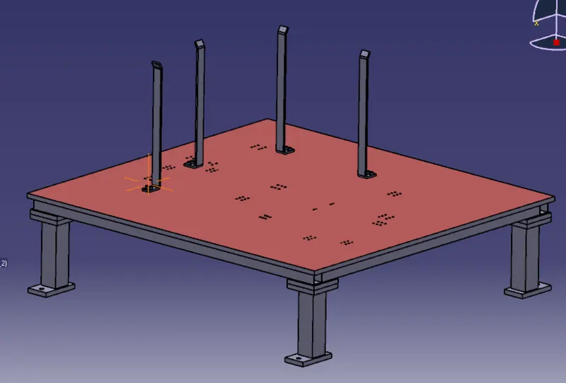
- Rough locators should be placed at the edges of the car panel.
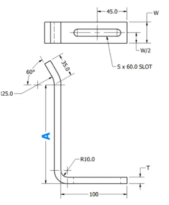
- Rough locators have to be placed at the same angle of the car panel edge with a minimum distance of 2-5 mm
- A rough locator should guide the panel in a pin arresting direction.
- Rough Locators should start guiding the panel before 10-15mm to start of pin engagement
- A rough locator should be designed with an entry angle for the car panel. It is generally it is between 30-45 degrees.
- Rough locators should be designed with slots to mount them
- The slots should be in the direction of the car part guiding.
5.What is the gun study process?
- welding is a very widely used process in automobile industries and most of the parts in an automobile is welded and there needs to be a proper way to do welding both manually or using a welding robot.
- The BIW used is a steel structure including 300mm to 500mm sheets with complex shapes and are assembled by means of welding.
- Spot welding is usually used in the BIW assembly process.
- During the design of the car panels, the designer provides the data of which spots of the panel is to be welded.
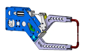
- The data provided by the BIW designer is used to check the feasibility of the weld gun to weld the panels.
- The fixture units must be positioned in such a way that the weld gun which performs the spot welding process does not interfere or hinder the welding process.
- The units are repositioned and reoriented if it is in the path of the weld gun.

6.What are the points need to consider during the gun study?
The points to be considered during the Gun study.
- The axis of the weld spot along the weld direction must be normal to the weld surface.
- The number of weld spots for the panel and the time required to spot each weld determines the total time required to complete all the weld spots
- If we have one or more device models and we want to program, the behavior of each model in the work cell can be simulated over time. Instruction for each device is coded by giving sequences.
- This sequence defines the motion and action of the devices.
- Based on the distance of each tag point from home position, motion type, speed and acceleration one can obtain cycle time for each device assigned with sequences. This way the robot cycle time is precisely calculated.
- After Sequencing all the devices, a simulation is run with collision check and made sure that the welding operation is collision-free.
7.What is pneumatic routing?
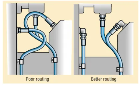
- Pneumatic routing is the process of arranging the hose carrying compressed air to the clamping cylinder, such that it operates in the desired way.
- Proper Pneumatic Lay outing or routing is very much important to be shown in the design, as it helps in describing the best possible way to keep all pneumatic pipes neat and away from welding spatters which can cause wear and tear of pneumatic pipes
- In Pneumatic lay-outing all pipes from the cylinders are shown connected to the valve box and pass through a safety box-like structure.
Points to be considered while pneumatic lay outing
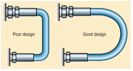
- Make hose assemblies longer such that there is no excessive bending beyond the bend radius.
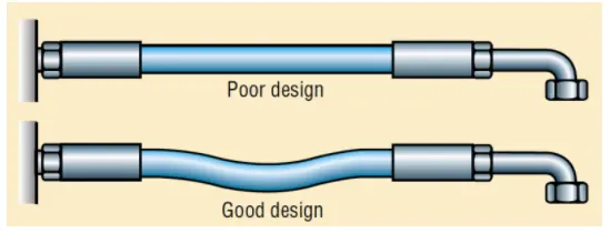
- The bending must be smooth and continuous and there must not be a sudden contraction in the pipeline which may cause irregular flow of the air.
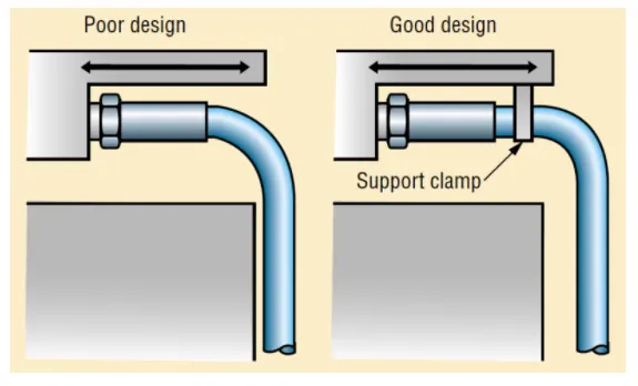
- The usage of Hose Clamps through the pneumatic layout will hold the hose in such a way that it does not come in contact with any other surfaces which might damage the hose.
- When there are multiple hoses, the routing must be in such a way that it does not get jumbled, which would result in reduced life of the hose and difficulty during maintenance.
8.What is the solenoid valve?
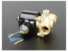
A solenoid valve is an electromechanically-operated valve. Solenoid valves differ in the characteristics of the electric current they use, the strength of the magnetic field they generate, the mechanism they use to regulate the fluid, and the type and characteristics of the fluid they control. The mechanism varies from linear action, plunger-type actuators to pivoted-armature actuators and rocker actuators. The valve can use a two-port design to regulate a flow or use a three or more port design to switch flows between ports. Multiple solenoid valves can be placed together on a manifold.
Solenoid valves are the most frequently used control elements in fluidics. Their tasks are to shut off, release, dose, distribute or mix fluids. They are found in many application areas. Solenoids offer fast and safe switching, high reliability, long service life, good medium compatibility of the materials used, low control power, and compact design.
Types of Solenoid Valves
There are 03 main different types of the Solenoid valve. a. Direct Acting Solenoid valve b. Pilot operated and c. Two-way solenoid valves. We will learn about those 03 types one by one.
Direct Acting Solenoid Valve
This type of solenoid valve has a coil that magnetically opens the valve in a direct action resulting in the core and seat of the to shift. Direct-acting solenoid valves use to energize by the magnetic field of the solenoid to operate. When the electrical current is not passing through the coil, a mechanical spring returns the valve to its original position.
pilot operated solenoid valve
In this type of solenoid valve, the plunger act according to differential pressure. Pilot-operated valves require less electrical energy to work to keep up full power with specific flow control. This type of valve performs at a slower rate than a direct-acting solenoid valve.
WORKING OF SOLENOID VALVE
Solenoid and Valve Body.
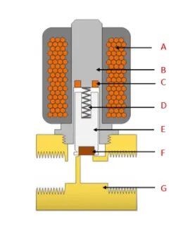
A solenoid has an electromagnetically inductive coil around its iron core at the center. At rest, it can be normally open (NO) or Normally Closed (NC). In a de-energized condition, a normally open valve is open for fluid flow while a normally closed valve restricts the flow of fluid.
When current passes through the solenoid, the coil gets energized and creates a magnetic field which creates an attraction with the plunger and moves it overcoming the spring force. If the valve is normally open, the plunger moves downward to close the flow and it is Normally Close then the plunger moves upward to allow fluid flow.
9.What is the valve bank?
A valve bank is the arrangement of a number of solenoid valves. Valve bank will have a common inlet port, a single servo line to each pneumatic valves, and an independent vent passage for each solenoid valve. On the solenoid bank, each of the solenoid valves separately controls the feed of high-pressure servo air to a pneumatic valve. The valve is actuated by selectively energizing the corresponding solenoid to allow servo air to the servo port of the valve. To return the valve to its fail-safe position, the solenoid is de-energized to vent the servo port of the valve to the ambient.
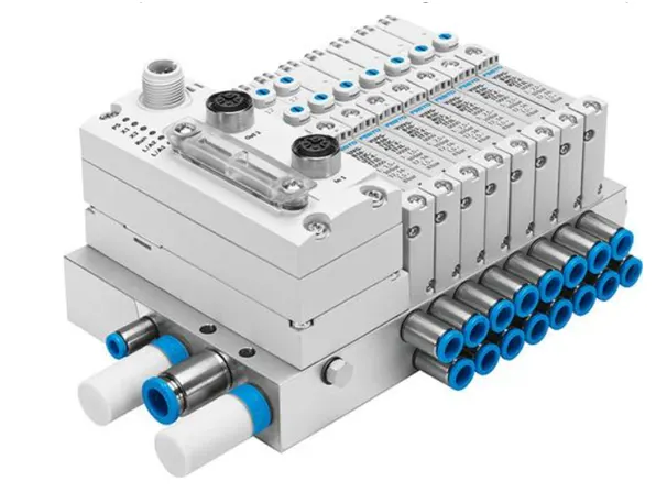
- These are designed for high vibration levels
- It uses aluminum alloy for lightweight
- These are designed for high-temperature environments
- Design architecture allows easy selection of two to six solenoids
10.What is a sensor & brief about its application in automation?
A sensor is a device, machine, or subsystem that detects events or changes in its setting and sends them in sequence to other electronics, often a computer processor. A sensor is always a part of electronics.
The term [sensor] refers to a measuring element that detects the magnitude of a physical parameter and changes it to a signal that can be processed by the system. The active component of a [sensor] is commonly known as a transducer. The design of [sensor]s and transducers always involves some physical or chemical law or principle that relates the amount of interest to a measurable event.
In a broader meaning, sensors are devices or machines used to detect the presence of any physical object in the vicinity and send information about the same to the receiving end. The device is mostly used with other electronic devices. Any physical quantity like pressure, force, strain, light, etc., can be identified and converted into a desired electrical signal. Basically, these are classified as analog and digital sensors. Others include temperature, ultrasonic, pressure, and proximity sensors. It uses less energy and has high performance. Data is collected from the environment using sensors and used for the internet of things.
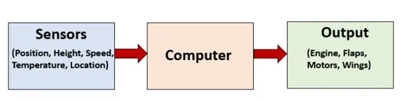
Sensors get information from the environment and transfer it to the computer. The system transfers the input to the needed output and displays it to the user.
11.What are the types of the sensor?
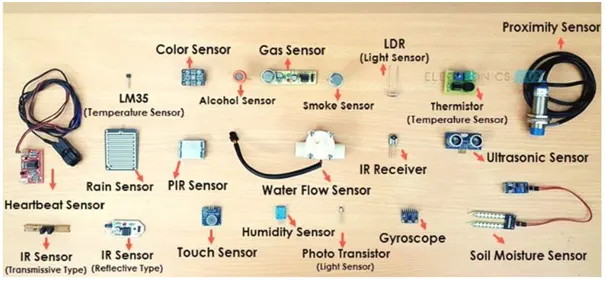
1. Temperature
It is used to measure the temperature in the environment and thus helps in knowing the variation in the temperature. They are used in the medical, automotive, aerospace and agricultural fields. Examples are thermocouple, thermistor, and a resistance temperature detector.
2. Light
It converts light energy into an electrical signal to see the output. They are otherwise called photo sensors or photoelectric devices. Mobile phones, computers, tablets use light sensors.
3. Pressure
This device is used to measure the pressure of liquids and gases. The pressure is measured, and it generates a signal as output. Examples are pressure transducers and pressure switches.
4. Ultrasonic
Distance between transmitting and receiving ultrasonic signals is measured using this sensor. They emit sound waves in a frequency that humans can’t hear. They are used in measuring liquid levels, detecting wire breaks, height control, robotic sensing, and so on. The types of ultrasonic sensors are Proximity and Continuous Level.
5. Color
They are used to detect colors and to recognize color marks. They should be able to distinguish between different colors. The color is detected in the RGB scale. The interaction between light source, object, and receiver are measured using Color Sensor. They are also used in the industrial and automatic control fields.
6. Touch
Touch works as a switch and does the specific operation when touched. The touch screen of mobiles and laptops are the perfect examples. They are sensitive to human touch, or any force applied or the pressure, and are made of light, magnets, or electricity.
7. Flow and Level
Flow and Level are used to determine the level of fluids in a particular space. It works on the principle of buoyancy. A magnet is connected to the device, and when the level rises, the magnet gives a signal to the switch that makes it work.
8. Smoke
The device that is used to detect smoke is called Smoke Sensor. They have a light source attached to them. When smoke occurs, the sensor makes the light reach the light sensor, making the alarm work. They are used in buildings, ships, airplanes, etc.
9. Accelerometer
Accelerometers are used to measure the acceleration of a particular device or a vehicle. Proper acceleration of the body depends on the motion or rest of the body, whereas coordinate acceleration depends on the body’s coordinate system. This is an inertial sensor and is used in vehicles, android devices, etc.
10. Infrared
The device that measures the infrared light emitted by objects within its view is called an infrared sensor. IR sensors either emit or detect infrared lights. Active and passive infrared sensors measure IR lights based on the warmth or the material. PIR detects heat from the environment.
11. Humidity
A humidity sensor is otherwise called a hygrometer. These are used to measure the moist or air temperature present in the atmosphere. The information from the sensor is used for measuring humidity to comfort people or in vehicles.
12. Tilt
This device is used to measure the tilt or rotation of the reference plane in different axes. This is used to measure the inclination or rotation of the surface. This can be used in vehicles as a safety alarm when an accident occurs.
12.What are the fundamental points that need to consider while designing or selecting a sensor?
1. Accuracy required:
It is the difference between the measured value and the true value. The accuracy of the sensor should be as high as possible.
2. Precision:
It is the ability to reproduce repeatedly with a given accuracy. It should be very high. The error between sensed and actual values should approach zero.
3. Sensitivity:
It is the ratio of change in output to a unit change of the input. It should be chosen to allow sufficient output.
4. Operating range:
It is the difference between the maximum and minimum values of the sensed parameter. Sensors should have a wide operating range and good accuracy over the range.
5. Resolution:
It is the smallest change in the sensor which can differentiate. Sensors should have high resolution.
6. Speed response:
Time taken by the sensor to respond should be minimum. Response time should be very less.
7. Reliability:
The reliability of the sensor should be high. Meantime to failure (MTTF) should be high. It results in the increased life.
8. Maintenance should also be easy and the frequency of maintenance required should be less over the period.
9. Calibration:
Sensors need frequent calibration for many reasons. Hence, it should be easy to calibrate. Drift should be as minimum as possible.
10. Cost:
The cost of the sensor should below.
11. The nature of output required from the sensor whether digital or analog has to be considered while selecting a sensor.
12. Linearity:
The sensor’s curve should linear. The percentage of deviation from the best-fit linear calibration curve should be less.
13. Environmental conditions:
Sensors should operate over wide environmental conditions such as temperature, corrosion, pressure, shocks, etc.
14. Interfacing:
Sensors should be compatible with different instruments for interfacing.
15. Size and weight:
Sensors should have a small size and less weight.