Hood design-Week 2
HOOD DESIGN USING NX CAD
OBJECTIVE
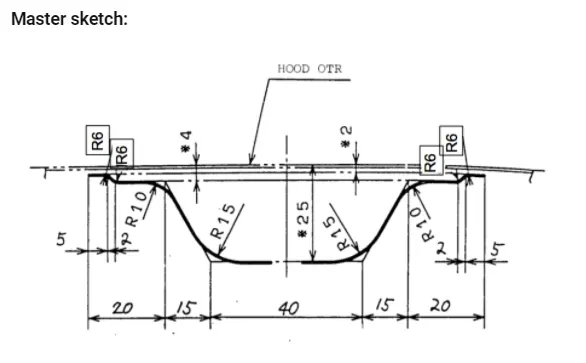
To Design the Hood outer panel, inner panel, and the necessary reinforcements by following the Master section.
INTRODUCTION
A hood is an important component in automobile BIW design. A hood is also known as a bonnet, which is used to cover the engine compartment. The hood can be opened in order to work on the engine components. The hood consists of an outer panel and an inner panel. The inner panel is designed in such a way that it provides strength and adheres with crash and safety requirements whereas the outer panel covers the inner panel and also adds aesthetic value to a car. The NX cad software is used in the whole designing process of the hood.
MASTER SKETCH
A master sketch is a predefined cross-sectional sketch, which provides data to design the hood inner panel.
PARTS OF THE HOOD ASSEMBLY
- Hood outer panel
- Hood Inner panel
- Hinge
- Latch
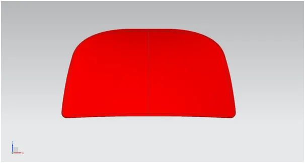
Hood outer panel
The hood outer panel is designed by the styling team which acts as an outer cover to the hood inner panel and also provides aesthetic value to a car. The thickness of the outer panel is 0.75mm.
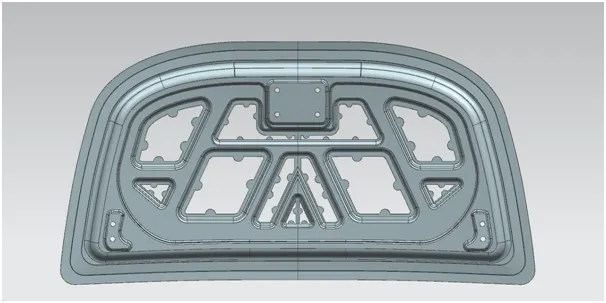
Hood inner panel
The hood inner panel is a vital part of the hood assembly as it plays a significant role in providing strength to the whole hood assembly. It is covered by the hood outer panel. The hood inner panel consists of embosses which are designed in such a way to dissipate the force acting on the front part of the car, away from the center to sideways so that the crash safety requirements are met. The basic structure of the inner panel is based on the master sketch. The inner panel also houses mastic points. The thickness of the inner panel is 0.75mm.
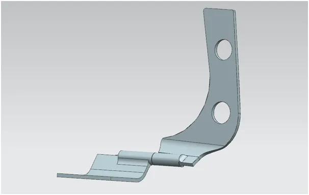
Hinge
The hinge connects the engine compartment with the hood. It also guides the opening and closing of the hood assembly.
Latch and Striker
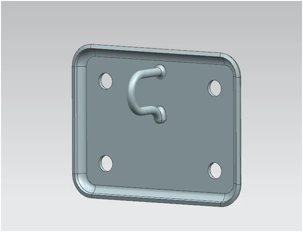
The latch enables the locking of the hood with the body of the car. The striker has the hook which helps in locking with the hatch.
HEMMING
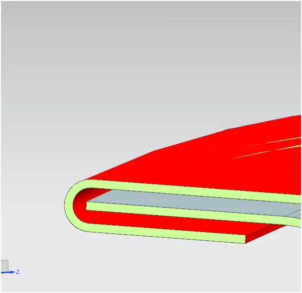
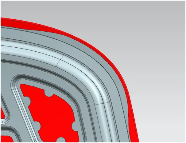
Hemming is the folding of the edges of the sheet metal to create round and safe edges. In this case, hemming is used to wrap the outer panel of the hood with the inner panel of the hood to hold them together. The hemming data is provided below
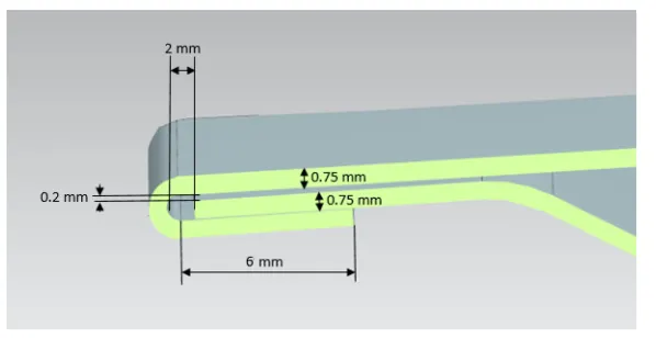
The actual hemming of the designed part
CORNER RELIEF
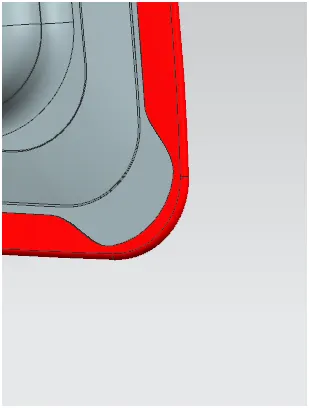
Corner relief is provided in the hood outer panel to have a smooth during the hemming process.
EMBOSSES
Embosses are the projections added to the surface of the hood inner panel in order to add more strength to it. The embosses in the hood inner panel are designed in such a way that, the force acting on the frontal part caused due to the crash is being dissipated away from the center of the car, to ensure the passenger safety. They are created using the deep drawing process during the manufacturing of the hood inner panel. Deep drawing is a process in sheet metal forming by the mechanical action of a punch. A flat sheet metal blank is formed over a single, rigid, shape defining tool half by a flexible rubber diaphragm under uniform hydrostatic pressure.
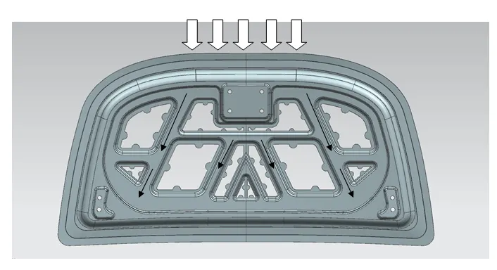
The above image shows the dissipation of force away from the center of the hood.
MASTIC POINTS AND MASTIC SEALANTS
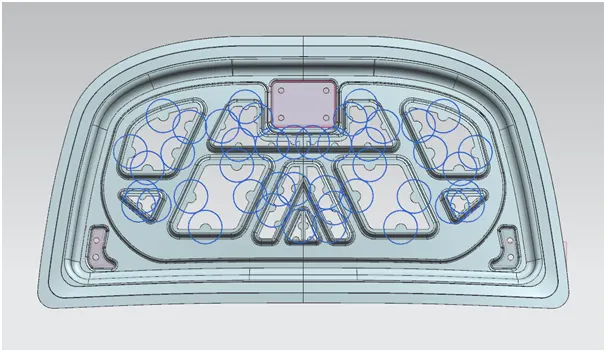
The hood inner panel is provided with mastic points, where the mastic sealants are applied to fill the gap between the hood outer panel and the hood inner panel. The mastic sealant is a hard rubber-like paste. They can be used instead of spot welding, which tends to affect the finish of the vehicle. The mastic sealants are significant in locally improving the strength of the hood inner panel up to a particular diameter from the mastic points and are placed such that almost the whole hood panel is covered. They are also helpful in improving the NVH levels. The image provides the mastic data.
TRAJECTORY PATH OF HOOD
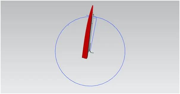
The hinge axis line is drawn such that it joins the center point of both the hinges. The distance from the midpoint of the hinge axis line and the midpoint of the striker is taken as the radius, with this radius a circle is drawn. This circle represents the trajectory path of the hood. It is to be noted that the circle passing through the striker must be perpendicular to the striker locally, in order to ensure proper closure of the hood. The position of the hinge axis must be corrected until the condition is obtained. The blue circle in the below image represents the trajectory path of the hood assembly.
BELOW ARE IMAGES OF FULLY ASSEMBLED HOOD
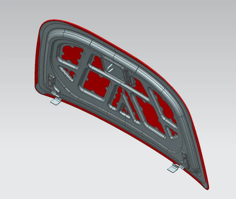
ISOMETRIC VIEW
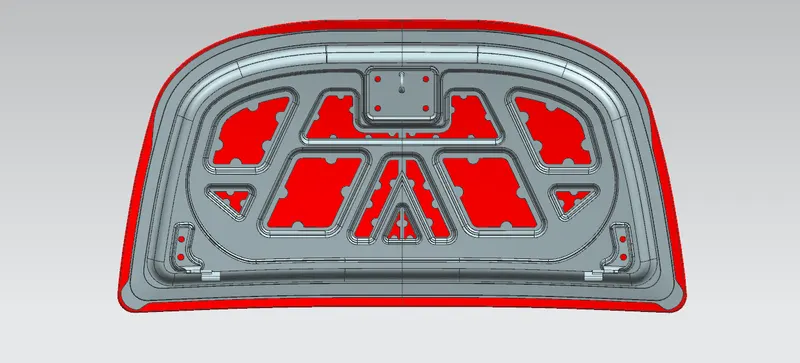
FRONT VIEW
CONCLUSION
Thus, the Hood outer panel, inner panel, and the necessary reinforcements were designed by following the Master section.