Week 8:- 3D Finishing Challenge 2
AIM
To Perform 3D finish and create Rough locators for the Assembly Fixture design.
INTRODUCTION
3D Finishing is a process where the design is being complete and to be ready for final simulation and 2D detailing. This is the stage in the process where the position of rough locators is identified.
During the 3D finishing process, the following points must be ensured:
Hole concentricity and the hole sizes
Hole concentricity is checked and confirmed for all the parts in a unit for easy assembly while finishing the parts.
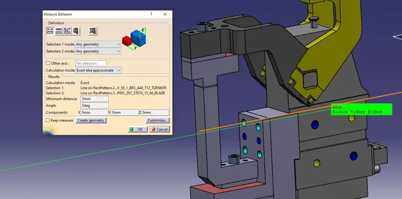
Machining Area
The machining area in every part should be designed and the machining area should be highlighted using standard color. The below image shows the machining area highlighted.
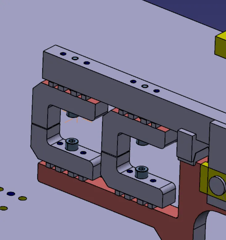
Nominality
All unit's dimensions should have nominal values to facilitate easy assembly of the unit. The below image shows the unit being placed with nominal distance and the same has been done for every other unit in the fixture assembly.
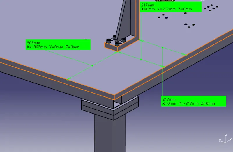
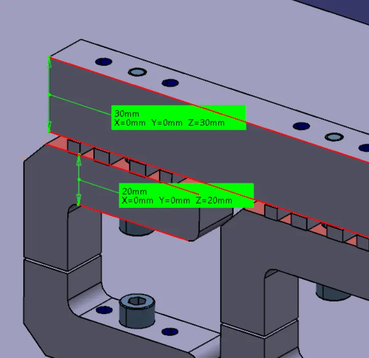
The dimensions of every part of each unit are also given nominal values so that it becomes easy to manufacture and assemble.
Holes colouring standard
In a 3D finishing process, hole colouring should be done in order to identify the type of holes. The dowel hole is given Blue colour, Threaded Hole should be coloured with yellow and the counterbore, the open hole should be given Cyan blue colour.
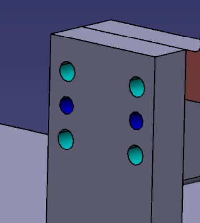
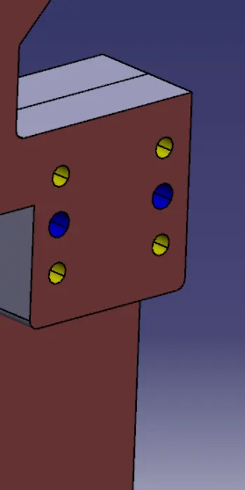
Pneumatic Lay outing
The pneumatic lay outing is a collection of different pneumatic pipes which gives compressed air to the cylinders. The lay-outing must be proper to have the proper working of the units.
Gaps Checking
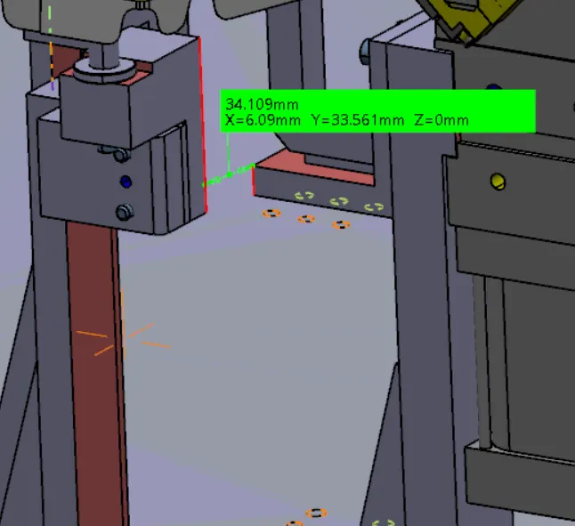
A proper gap of at least 5mm should be maintained between different units to avoid the clash between them.
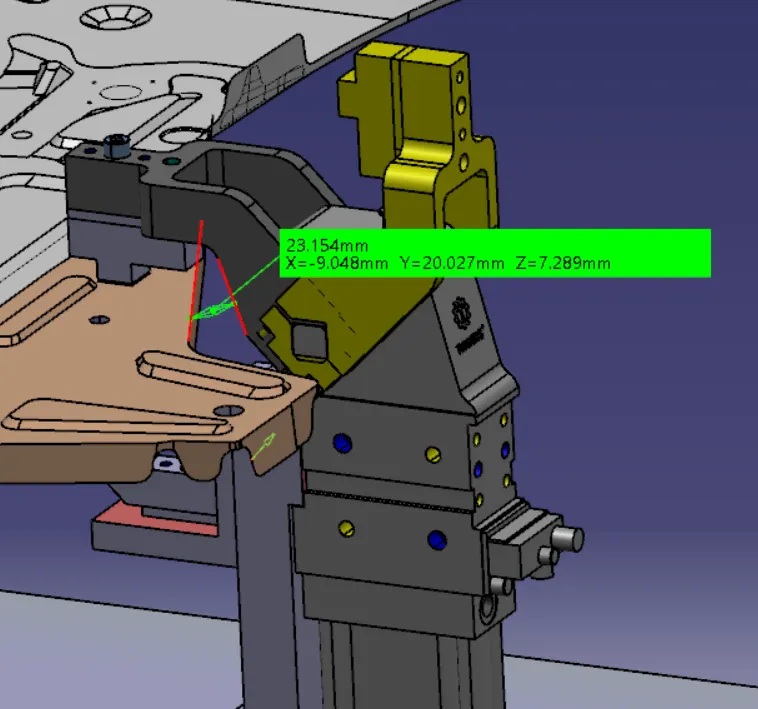
The above image shows the gap between the unit and the panel. Similarly, the gap between different units is also measured.
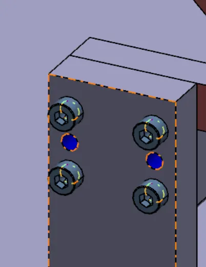
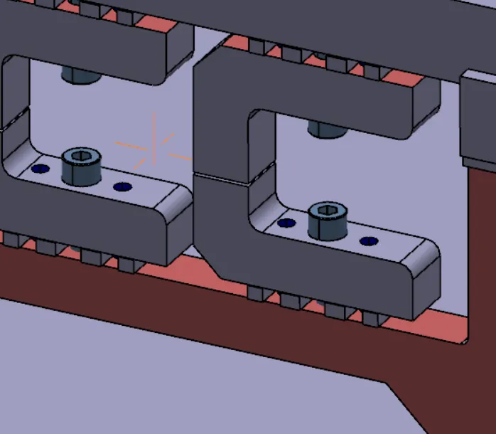
Fasteners implementation
Fasteners should be implemented in all the units as per the requirement.
Mylar Splitting as per panel profile
Mylar Splitting should be confirmed while the design finishing the design. The thickness of the panel should be taken into account while splitting the panel.
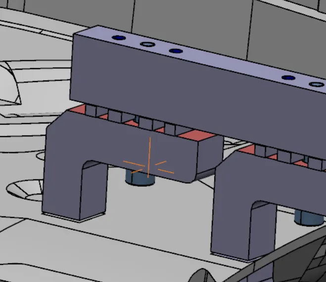
The above image shows the clamp mylar splitting the panel profile with a thickness of 1mm.
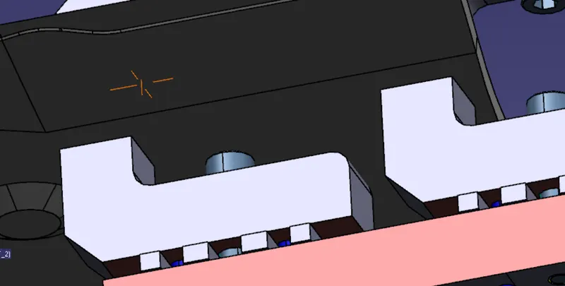
Splitting of the panel bottom profile with rest mylar.
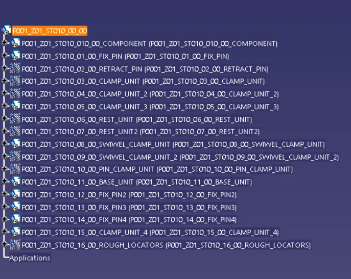
Proper renaming of parts as per the standard
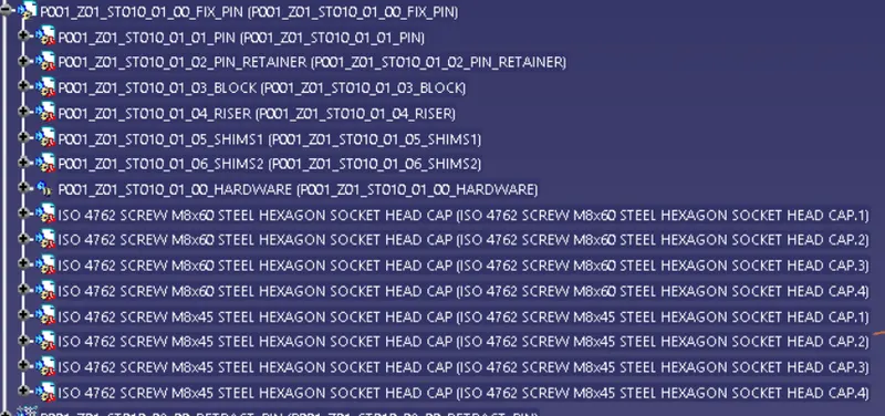
Proper renaming of the parts and products in the specification tree is important so that it will be easily identifiable.
All the 3D finished Units
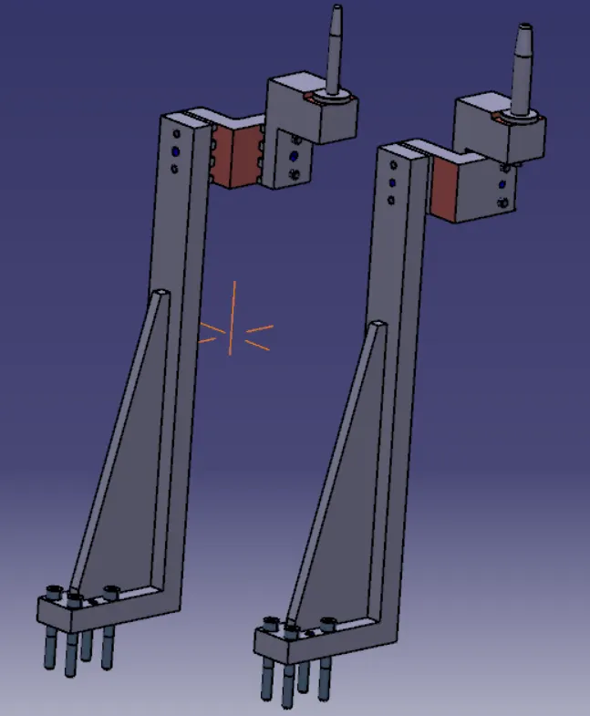
Pin Units
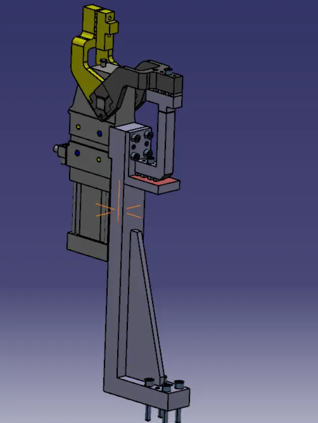
Clamp unit
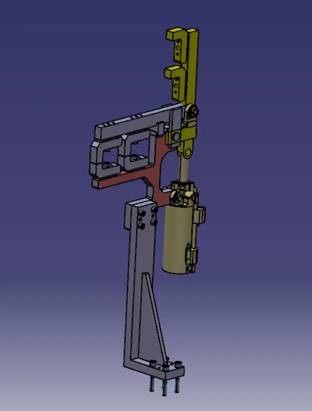
Swivel Clamp unit
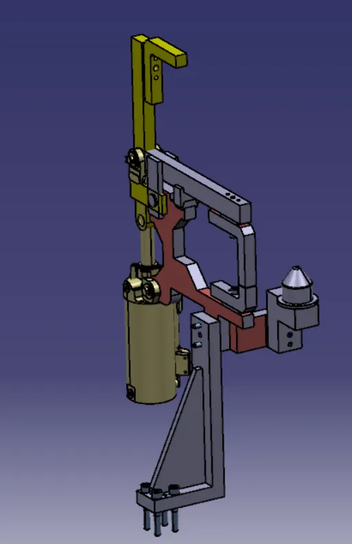
Pin Clamp Unit
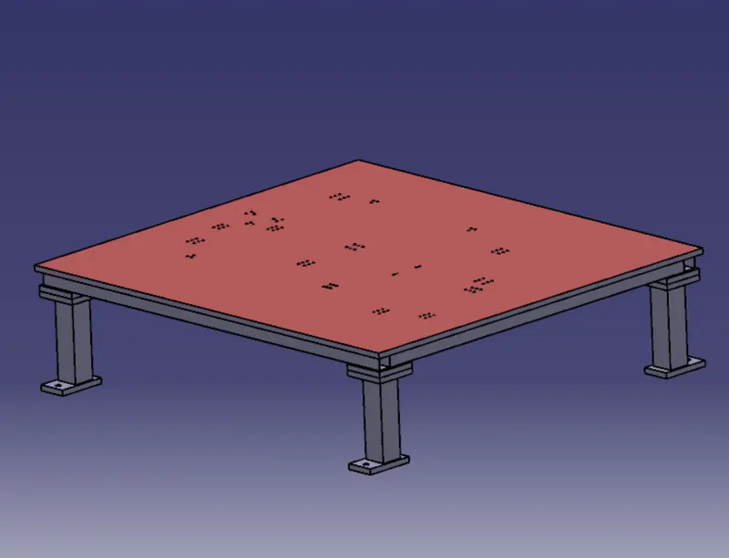
Base Unit
3-2-1 Principle
The 3-2-1 method is a work-holding principle where three pins are located on the 1st principle plane, i.e. either XY, YZ, ZX. And two pins are located on the 2nd plane which is perpendicular to the 1st plane, and at last one pin on the plane which is mutually perpendicular to the 1st and 2nd planes. The ultimate goal is to constrain the movement of the workpiece along all three axes.
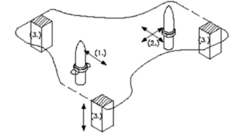
3.Minimum
From the above figure, We can see three locator blocks positioned at the primary locating surface. These three locators restrict the axial upward and downward movement along with it the two radial movements both clockwise and Anti clockwise are also restricted. So, a total of four radial movements is restricted to the two mutually perpendicular axes.
The three locators, on the whole, have restricted six Degrees of freedom.
2.Round Locating Pin
The pin added in the location of the hole restricts the axial movements of two perpendicular axes (both positive and negative). Thus, restricting Four Degrees of freedom.
1.Round Locating Pin
The round locating pin is added to the slot in order to restrict the remaining radial movement in both clockwise and anti-clockwise. This, therefore, restricts the remaining two degrees of freedom.
Thus, the 3-2-1 principle is used to restrict the 12 degrees of freedom of a part.
ROUGH LOCATORS
- Rough locators are basically used where manual loading of panels are to implemented on the fixture
- These are used to guide the panels in correct position and orientation.
- These also help for proper poka - yoke
- Materials used for rough locators are Mild steel and similar metals.
- The accuracy of the locating components directly affects the consistency and how the final product will come out.
- It can be called as a fool proofing method.
- Fool proofing is a method by which ensures that the workpiece will fit into the fixture only if it is placed in the correct position.
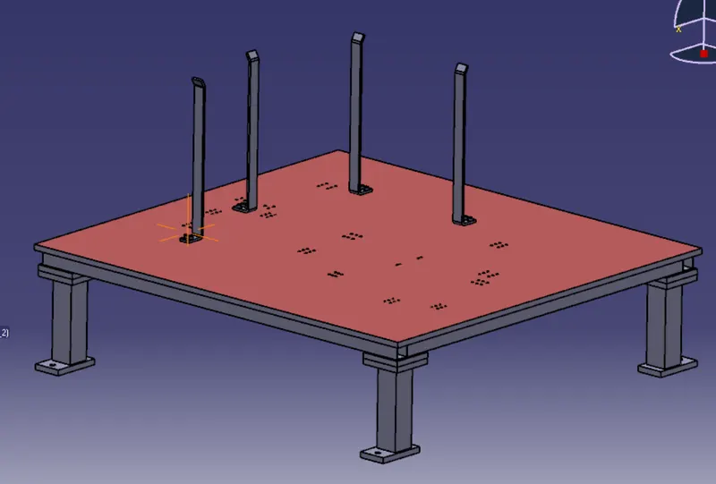
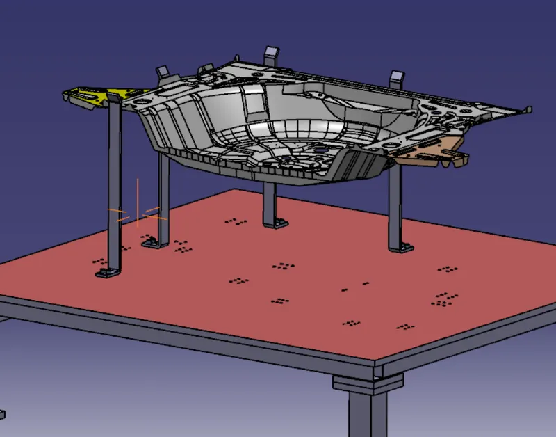
The rough locators are placed at places where the panel has different shape so that it will be easy for loading and unloading . The placement is also done such that it does not clash with any other unit.
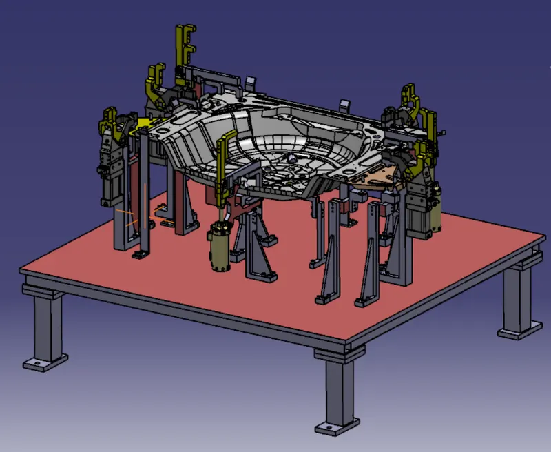
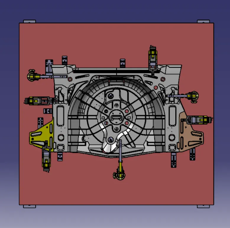
Final Assembly of 3D Finished Fixture
CONCLUSION
Hence, the 3D finishing was done to the fixture assembly with all the requirements. The file is named 3DFinishing_suhail and the project name is P001_Z01_ST010_00_00.CATProduct.