Roof challenge
CAR ROOF DESIGN USING NX CAD
OBJECTIVE
To design a car roof using the Given Roof styling, Develop the essential flanges and reinforcements, Provide appropriate dimension and check for Draft analysis and do a curvature study using heat distortion criteria and snow load criteria formula.
INTRODUCTION
An automobile roof is a part that lies above the passenger's head, which helps in protecting the passengers from the sun, rain, and other external things.
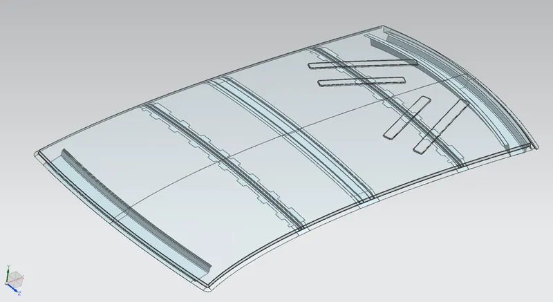
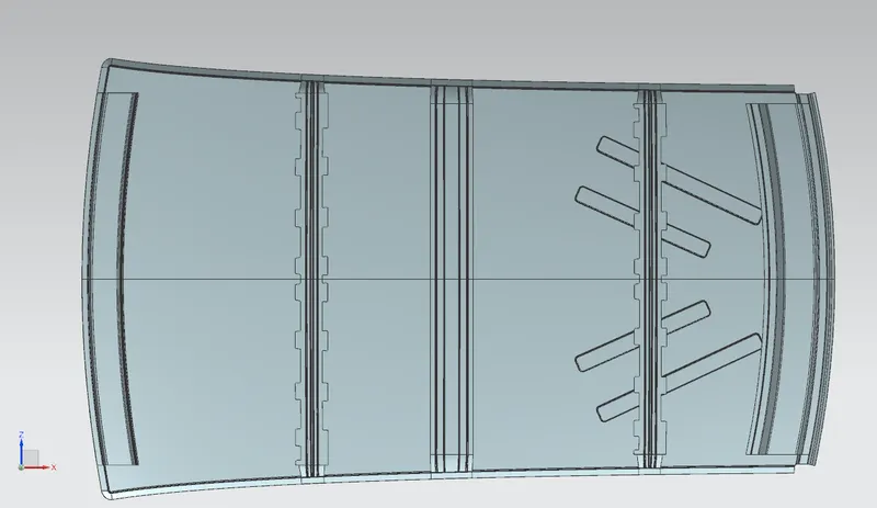
The design of the roof consists of many parts beneath the outer panel in order to add more strength to the roof. Many factors like headroom criteria and visibility criteria are to be considered while designing the roof. The outer styling surface is known as the ditch area, reinforcements like front roof rail, rear roof rail, center roof rail, and bow roof rails are assembled with the ditch area. The number of bow roof depends upon the length of the vehicle.
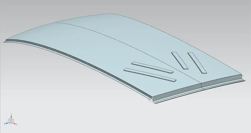
DITCH AREA
The Ditch area is the part of the roof which is welded and joined with the other Biw components of the car. The reinforcements are assembled with the ditch area using mastic sealants and spot welds. The thickness of the ditch area is 0.75mm. Headroom criteria visibility criteria and space for backdoor mountings are to be considered while designing the ditch area.
FRONT ROOF RAIL
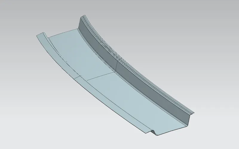
The front roof rail acts as a support for the roof sheet and it also provides a mounting area for the windshield. The support requirements, visibility criteria, and headroom criteria are to be considered while designing the front roof rail. The front roof rail is fixed with the roof outer with mastic sealants and spot welds. The thickness of the front roof rail is 0.75mm.
REAR ROOF RAIL
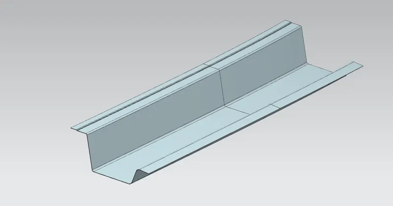
The rear roof rails act as supports for the rear end of the roof and also helps in mounting the rear glass. The design depends upon the backdoor and the mounting space for the backdoor is also considered. The visibility criteria and headroom criteria are also to be considered while designing the rear roof rail. The thickness of the rear roof rail is 0.75mm.
CENTER ROOF RAIL
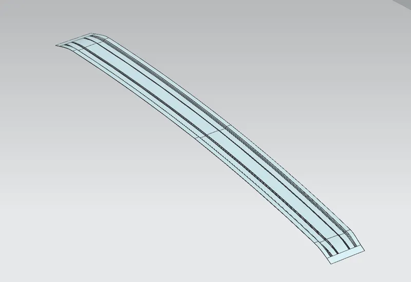
The center roof rail runs between the B pillar of the car and provides support and adds strength to the ditch area. The center roof rails are attached to the roof using the mastic sealants. The thickness of the Center roof rail is 0.75mm.
BOW ROOF RAILS
The bow roof rails provide additional support to the roof. The bow roofs are usually placed in flatter regions in order to add more strength to the roof. It must be placed in such a way that it does not hinder the headroom criteria. The bow roof rails are attached to the roof using the mastic sealants. The thickness of the Bow roof rail is 0.75mm.
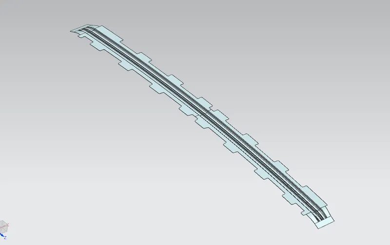
Bow roof 1
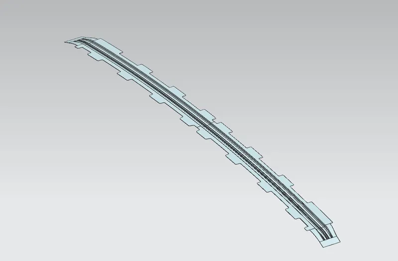
Bow Roof 2
Final Roof Assembly
ANALYSIS
DRAFT ANALYSIS
Draft analysis is done to analyze the draft angle of every part. The draft angle is provided for the easy removal of the tool from the part after the drawing process of each part. We have considered a draft angle of 7 degrees and performed the draft analysis on NX cad.
Below are the draft analysis imaged of various parts of the roof assembly.
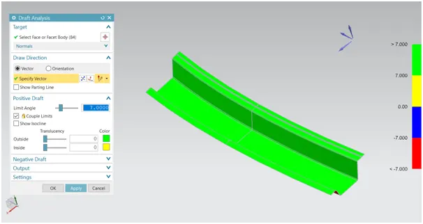
Rear roof rail
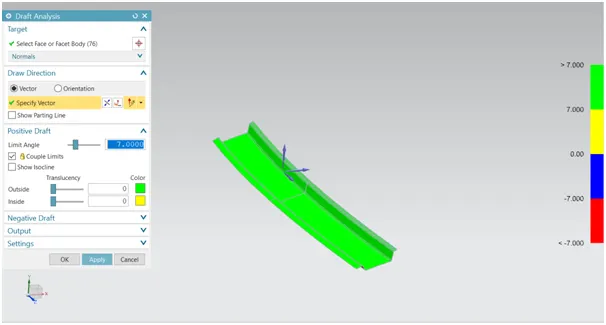
Front roof rail
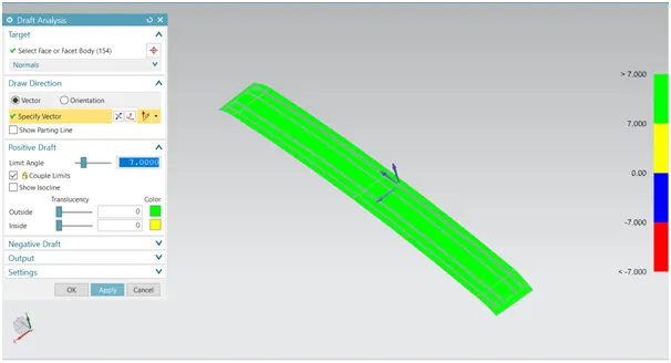
center roof rail
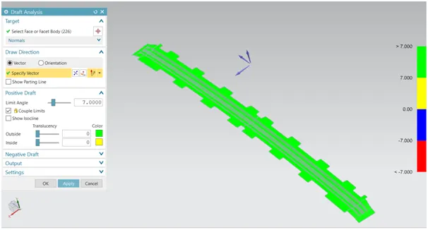
bow roof 1
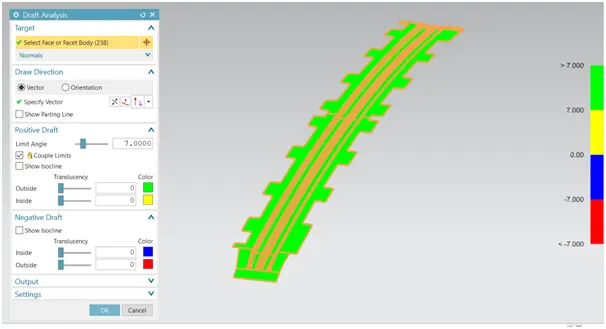
bow roof 2
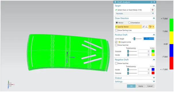
Ditch area.
CURVATURE STUDY
The curvature study is done to check the positioning of the bow roofs. Heat distortion and snow load criteria must be satisfied, if not, necessary changes must be made.
HEAT DISTORTION CRITERIA
Heat distortion temperature is the temperature at which the metal deforms under the application of the load. the heat distortion criteria help to position the reinforcements such that the failure due to the high temperature is prevented. Below is the formula for heat distortion criteria.
W = [1.73 x 10^(-3) x L] + [1.85 x 10^(-8) x (R^2)/t] + [ 1.10x10^(-3) x l] - 2.68
Judgement Condition : OK< 2.7> 3.1
Where
L = Roof Length in X-Direction[mm](Roof dimension in 0-Y)
R = Roof curvature
R = 2(Rx*Ry)/(Rx+Ry)
Rx = X curvature
Ry = Y curvature
t = Roof plate thickness [mm]
l = Bow Roof Span [mm]
Heat distortion criteria table

FR - Front Roof rail
BOW 1 -Bow roof 1
BOW 2 -Bow roof 2
CR - Center Roof rail
RR - Rear Roof rail
SECTION ANALYSIS
Section moment of inertia is used to determine the deflection and deformation of any particular body. Higher the moment of inertia lesser the deformation.

Section inertia of front roof rail
I= 7.946*10^3 mm^4
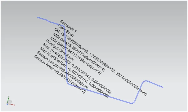
Section inertia of Rear roof rail
I= 7.847*10^4 mm^4
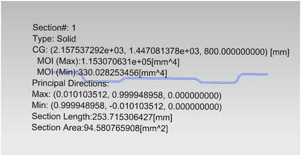
Section inertia of Center roof rail
I= 330.028 mm^4
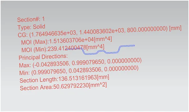
Section inertia of Bow roof 1
I= 239.41 mm^4
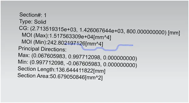
Section inertia of Bow roof 2
I= 242.80 mm^4
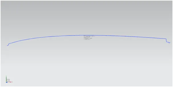
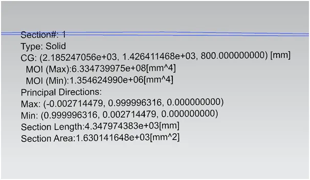
Section inertia of roof outer
I= 1.354*10^6 mm^4
SNOW LOAD CRITERIA
It is the ability of the roof to withstand the load due to the snowfall and to regain its shape after deformation due to the load.
Snow load Prediction formula
Qr = [Iy x t2] / [α x s x [(Rx + Ry)/2]2 x 10-8]
Where
α = My x Lx2 x 10-12 , My = Y(Ly-Y)
Judgement condition = Qr ≥ 3.1
250 ≤ s ≤ 380
t = Roof plate thickness [mm]
Ly = Distance between the front and rear roof Rails on the Vehicle along with 0Y[mm]
Length of Roof panel with the center point between Roof rail Front /Rear as the reference point of the front and the rear.
Lx = Distance between the Left and Right end of the roof on the Roof BOW [mm]
Width of the roof panel exposed on the surface.
Y = Distance front Front Roof Rail to Roof BOW[mm]
s = Distance for which Roof BOW bears divided load [mm]
s = L1/2 + L2/2
Iy = Geometrical moment of inertia of Roof BOW (Y cross-section )[mm4]
Rx = Lateral direction curvature radius of roof panel Y cross-section on Roof BOW [mm]
Roof panel curvature Radius of the Length Lx in Front view
Ry = Longitudinal Direction curvature radius of the Roof panel X cross-section on Roof BOW [mm]
Roof panel X curvature radius of length s in Side view
Snow load criteria table

FR - Front Roof rail
BOW 1 -Bow roof 1
BOW 2 -Bow roof 2
CR - Center Roof rail
From both heat distortion criteria and snow load criteria tables, it is clear that heat distortion criteria are satisfied, whereas the snow load criteria failed between Center roof rail and bow roof 2 failed.
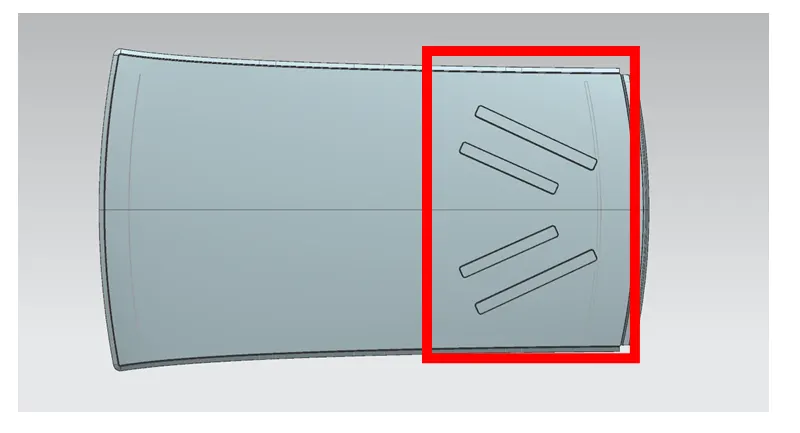
So, in order to add more strength to the roof, additional embosses can be added to the region where NG is obtained.
Below is the image of the additional emboss added to the region where NG was obtained.
CONCLUSION
Thus, the car roof was designed using the provided styling surface and additional reinforcements were added to provide strength. The analysis was done for the draft angle, heat distortion criteria, and snowload criteria, necessary modifications were made where the criteria were not satisfied.