Door Arm Rest Week 8 Challenge
AIM
To create a Class B and Class C surface from the given class A surface of the Door Armrest and add thickness to it. To perform a draft analysis of the component.
Firstly, the connectivity of the given Class-A surface must be checked, and ensure that there are no gaps between the surfaces.
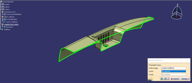
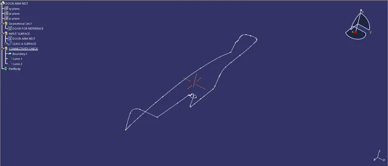
- t is clear from the above images that all the surfaces are continuous without any gaps in between them.
- We can further disassemble the boundary so that the continuity is clearly visible.
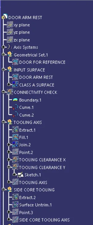
Creation of tooling axis for the given Class-A surface
- Tooling Axis direction is the direction in which the core and cavity open.
- The selection of tooling direction depends upon the product and the features of the product.
- The tooling direction is selected by visually checking the part and in such a way that there are no additional side cores required for the molding process. This ensures proper clearance of the part after the process.
The below are the steps for creating the tooling axis.
- Create a point at the bottom surface of the giver door armrest class A surface, and insert an axis system at that point.
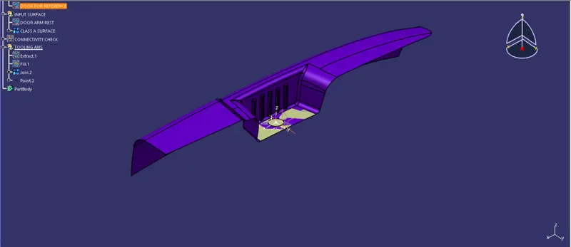
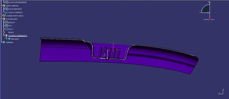
An intersection is created between the ZX plane and the Class A surface to get the tooling clearance in the X-direction.
- lines are drawn to represent the faces parallel to the assumed tooling direction.
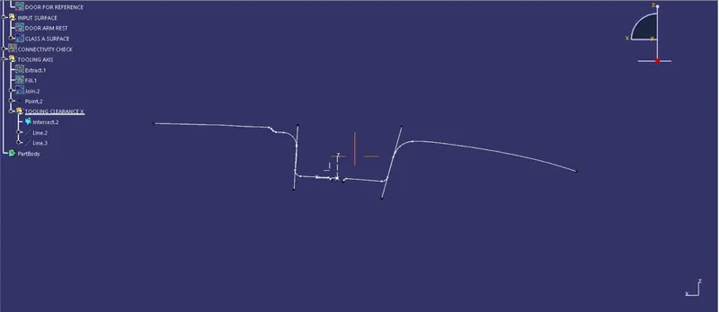
- Bisect the two lines to get the tooling clearing line in the X-direction.
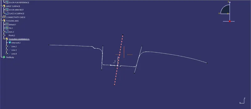
The above line denotes the Tooling clearance in the X-direction.
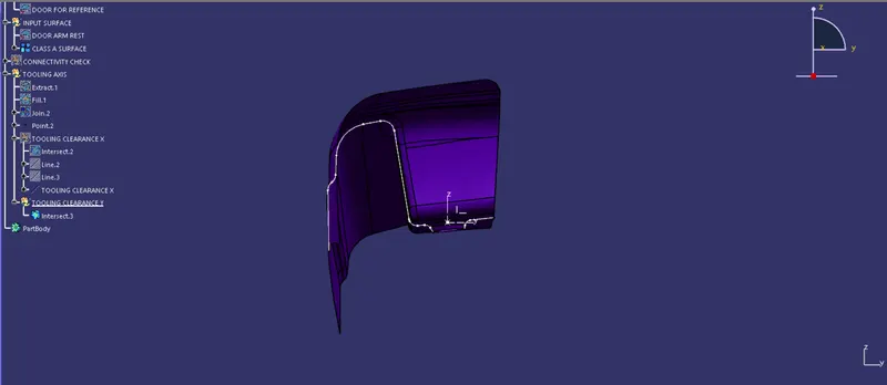
- Similarly, Create an intersection between the part and the ZY plane, that will give two curves as output.
- lines are drawn to represent the faces parallel to the assumed tooling direction.
- Since we do not have an opposite face we cannot bisect the lines to create a tooling axis. we create a line based on the required draft angle with the parallel face.
- That line represents the tooling clearance in the Y direction.
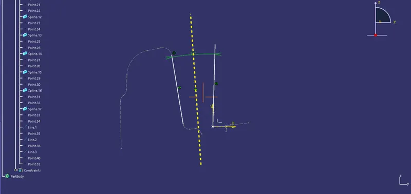
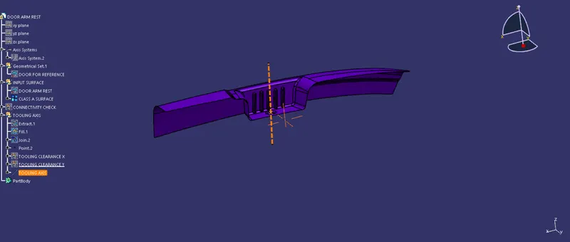
- Now, bisect both the tooling clearance y and tooling clearance Z to create a tooling axis.
Draft Analysis
When developing parts for plastic injection molding, applying a draft (or a taper) to the faces of the part is critical to improving the moldability of your part. Without it, parts run the risk of poor cosmetic finishes and may bend, break, or warp due to molding stresses caused by the plastic cooling. Equally important, an absence of a draft may prevent parts from ejecting from the mold, damaging not only the parts but possibly the mold itself—a costly and time-consuming detour.
In CATIA the draft analysis can be found by Insert > Analysis> Feature Draft Analysis.
Generally, the nominal draft angle will be 3 degrees.
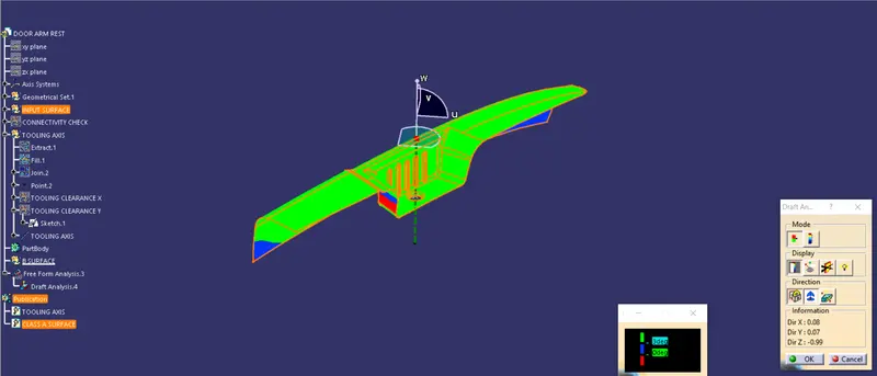
Draft analysis of the class A surface along the created tooling axis.
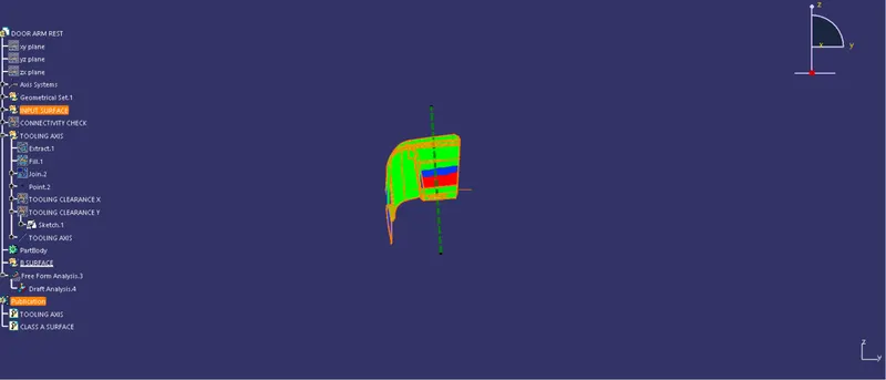
Front view
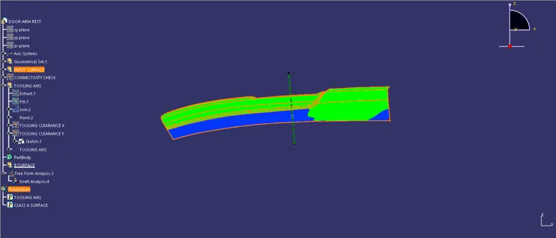
Left side view
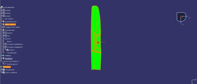
Top view
It is clear from the above draft analysis that some faces of the class A surface are not at the required angle. So, a side core is required to clear those faces.
Creating a tooling axis for the side core.
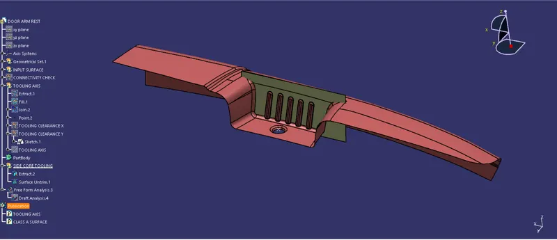
The above-shown face is extracted and untrimmed.
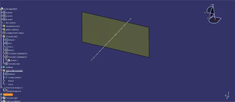
A point is created on the center of the surface and a line is drawn through the point along the Y direction
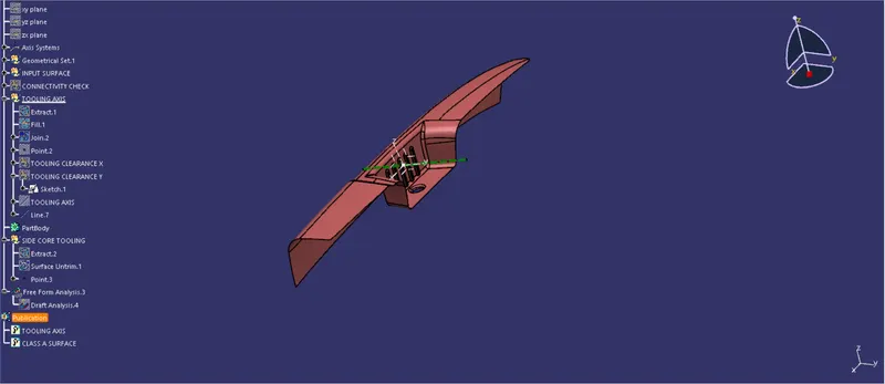
The line is tilted to a certain angle in order to clear the draft analysis with the help of an axis system.
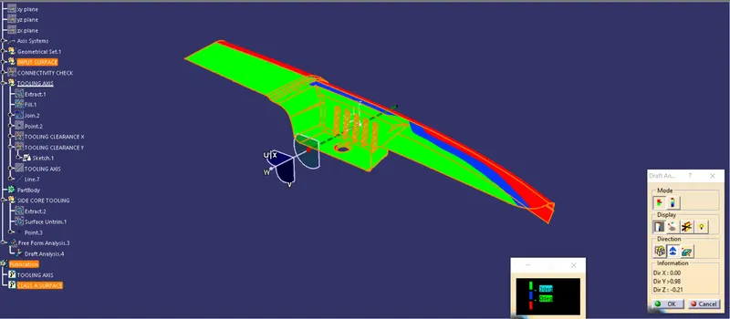
The side core tooling axis created clears the draft analysis of the surface which wasn't achieved using the main tooling axis.
The above image shows the side core axis clearing the front face.
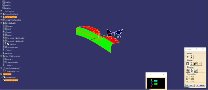
The above image shows the side core axis clearing the backside undercut.
Thus two side cores are dependent on the side core axis.
NOTE: The same draft analysis instance is used for both the main tooling and the side tooling analysis, due to an issue in the software.
Class B surface
It is a surface that is below a certain thickness from the class A surface. The engineering features of the product are on the class B surface while the class A surface is the styling surface.
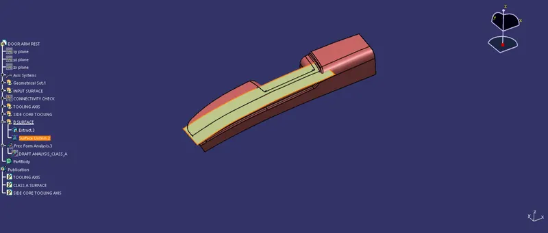
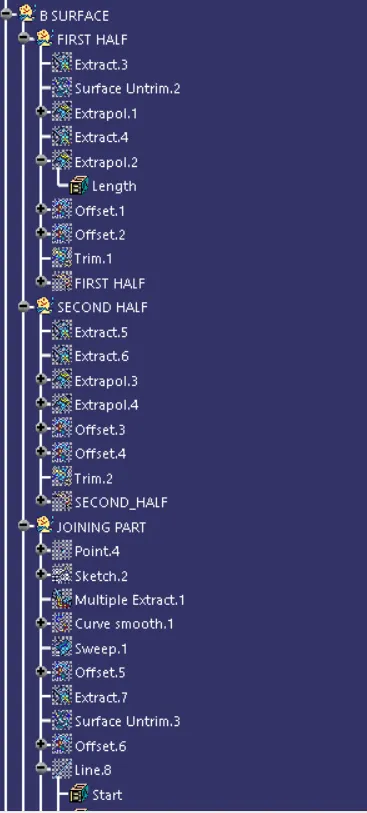
The top surface is extracted and untrimmed.
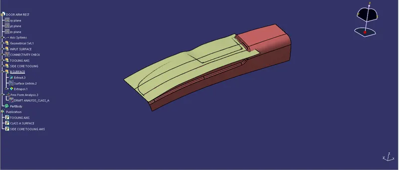
Then the surface is extrapolated
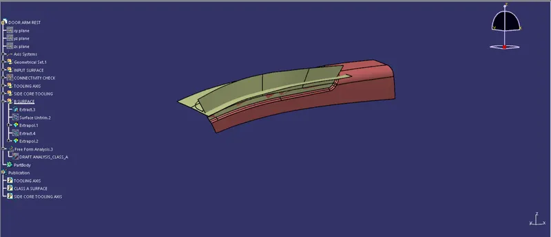
The side surface is extracted and then is extrapolated.
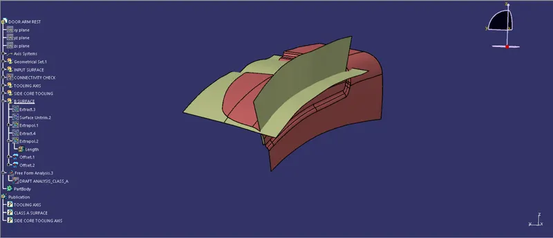
The two extrapolated surfaces are offset by 2.5mm
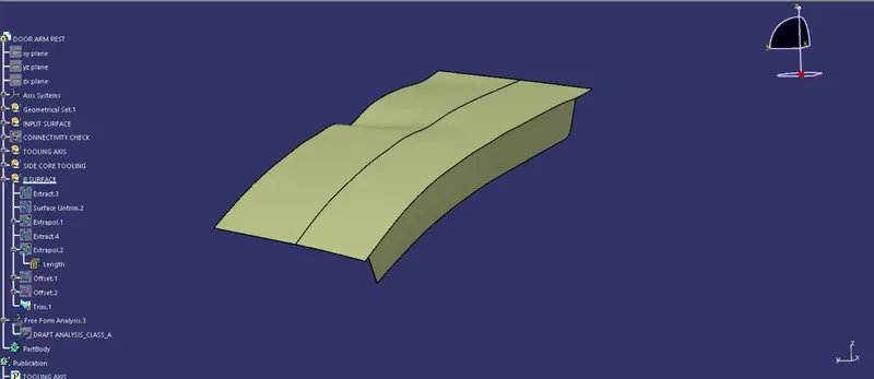
The offset surfaces are then trimmed together.
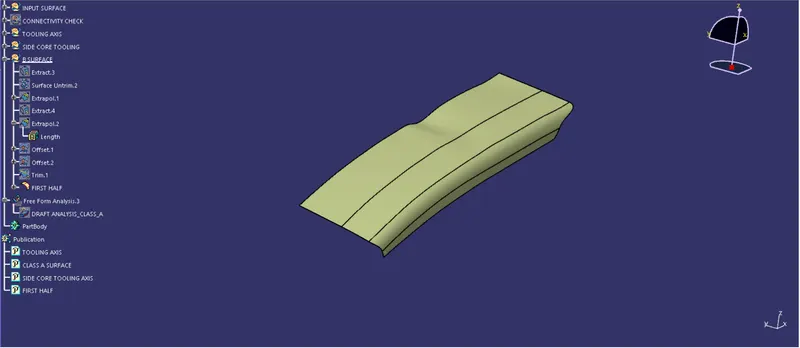
Fillets are added to the edges.
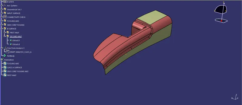
The surfaces are extracted as shown above.
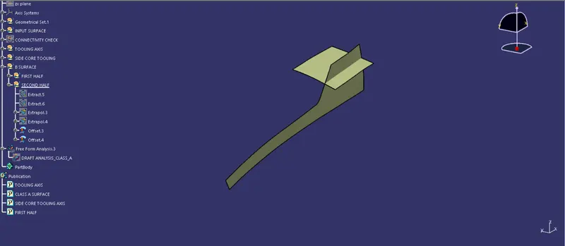
The extracted surface are extrapolated and offset by 2.5mm
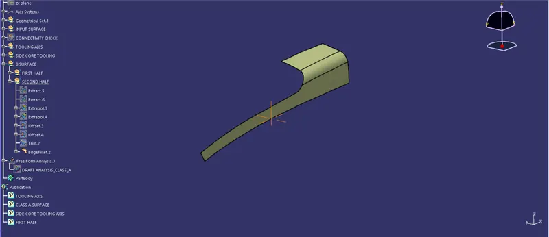
Further, they are trimmed and fillet values are added.
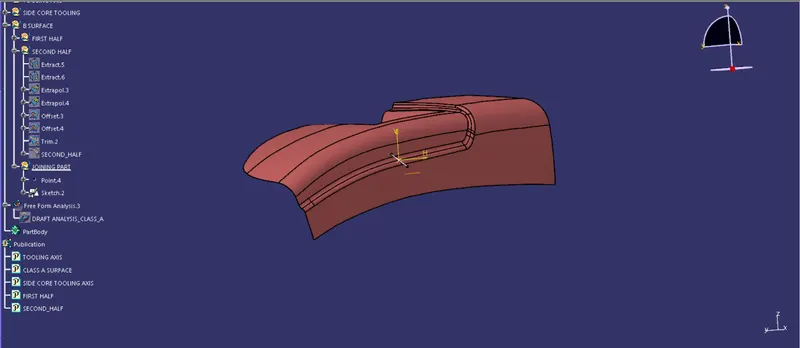
for the joining surface, draw create a point as shown above and draw a line tangent to the fillet surface.
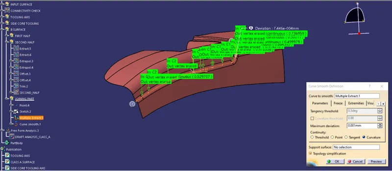
The lines along the joining surface are extracted.
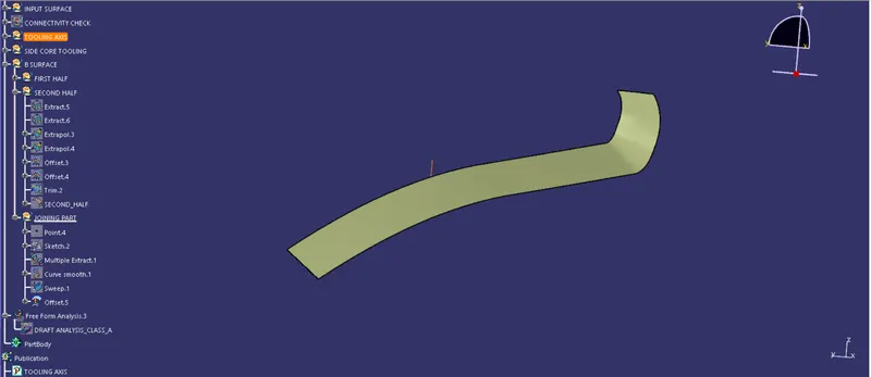
Sweep the surface along the selected curve and the profile. offset the swept surface by 2.5mm.
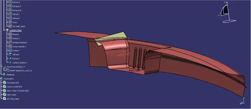
Extract and untrim the surface as shown in the above figure.
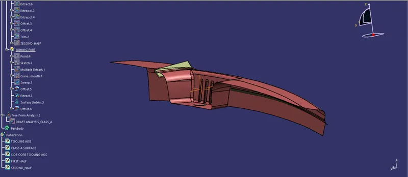
Offset the above-extracted surface by 2.5mm.
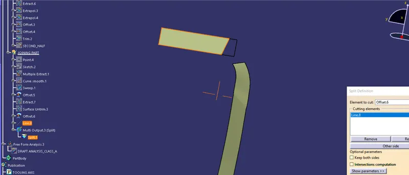
Further, the surface is split at an angle with a line created.
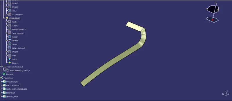
The two joining surfaces are connected together using the blend command.
The First half and the joining surface created are extended such that there is an intersection between the surface throughout.
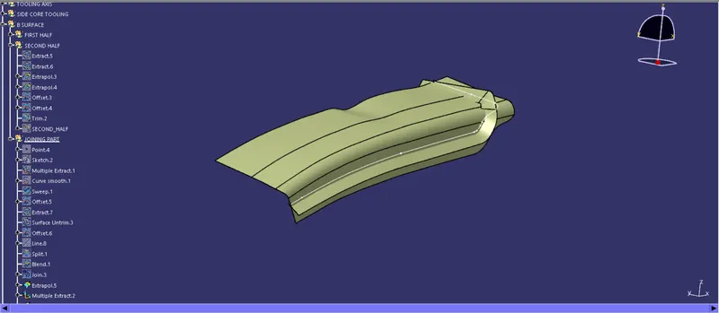
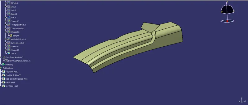
The First half and joining surfaces are trimmed.
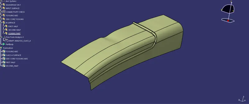
Similarly, the surfaces are trimmed with the second half surface.
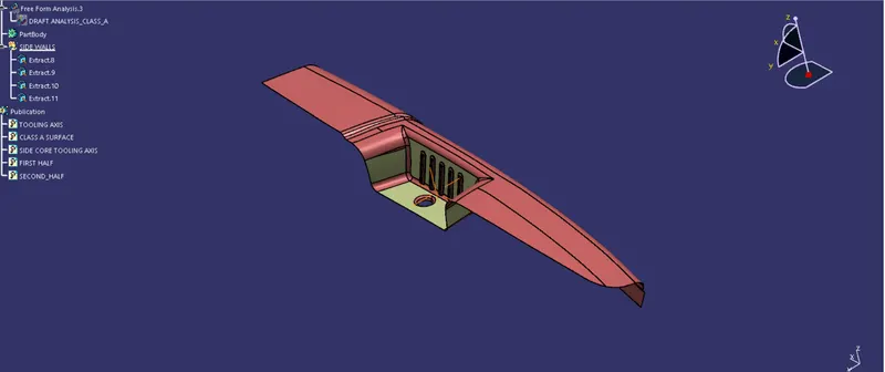
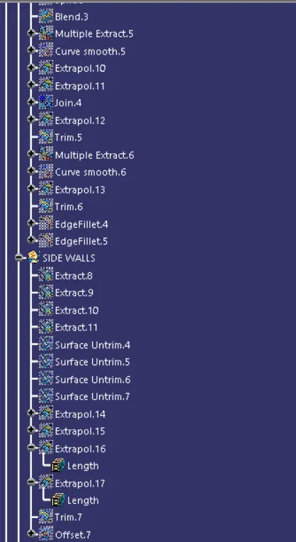
The three surfaces of the walls are extracted. Further, they are untrimmed and are extrapolated.
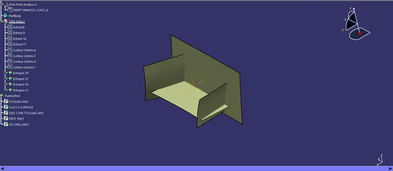
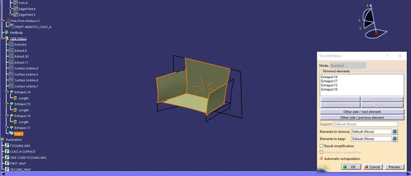
The surfaces are trimmed together and are offset by2.5mm.
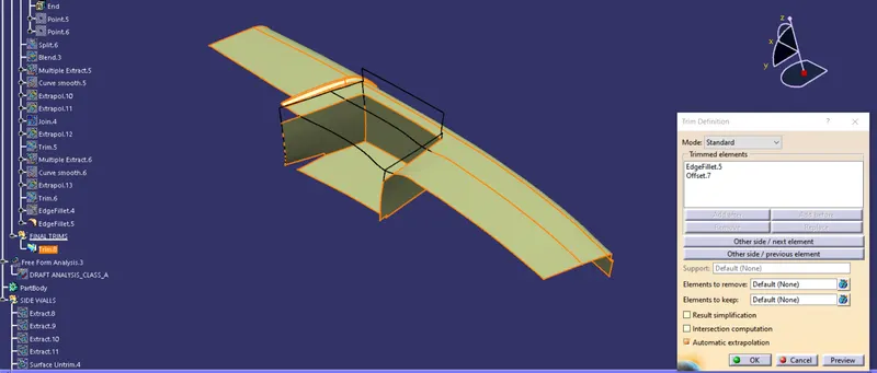
The Side faces are trimmed with the top surfaces.
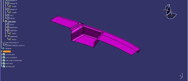
This is the final Class B surface.
Class C Surface
The Class C surface is the surface used to join class A and the Class B surface.
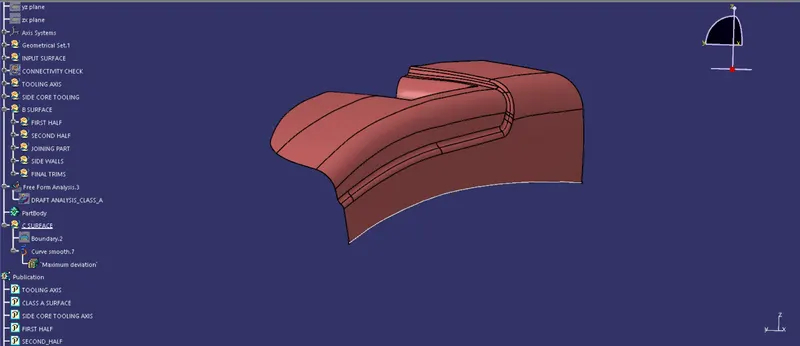
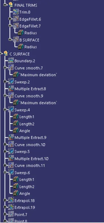
Extract the boundary of the back bottom surface.
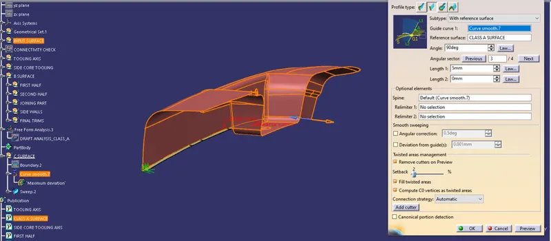
The extracted boundary is swept with the surface reference.
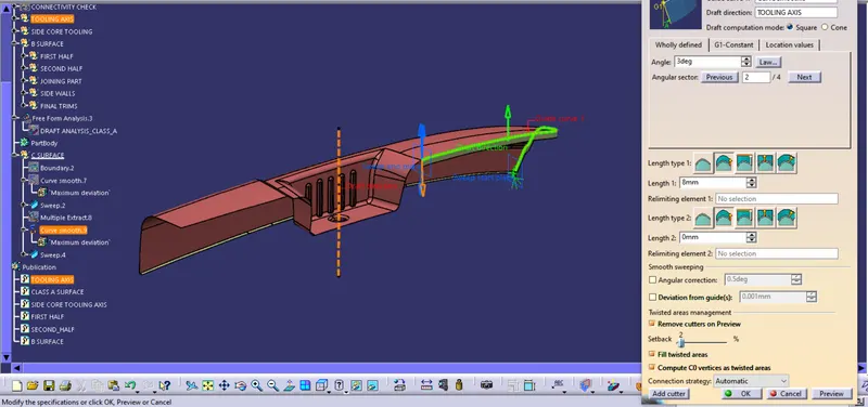
The remaining edges are extracted using multiple extracts and then the curve is smoothened. The smoothened curve is then swept along the main tooling axis.
It is done seperately on each set of curves to have proper orientation.
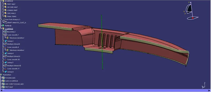
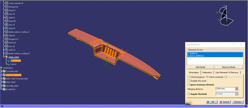
The c surface and the Class A surface are joined together.
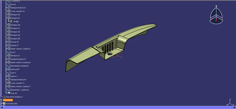
The B surface and the C surface are trimmed together to form the final surface outcome.
The surface is then converted to a solid body by the Closed surface command.
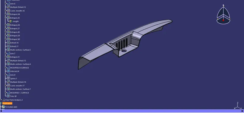
isometric view
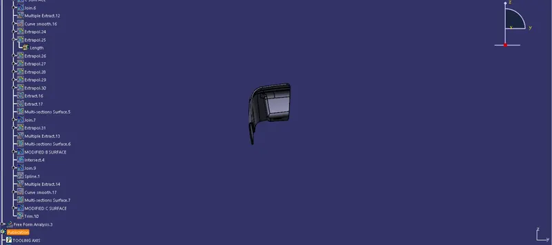
Front view
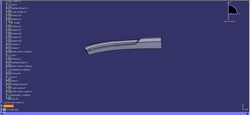
left side view
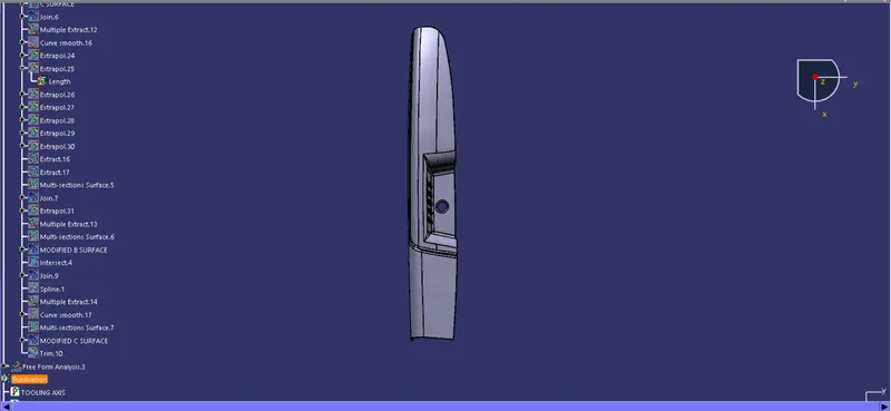
Top view
DRAFT ANALYSIS OF THE SOLID PART
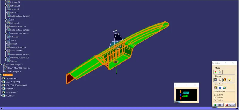
Draft analysis about the main tooling axis.
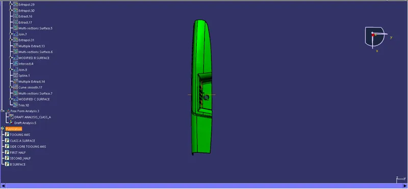
Top view
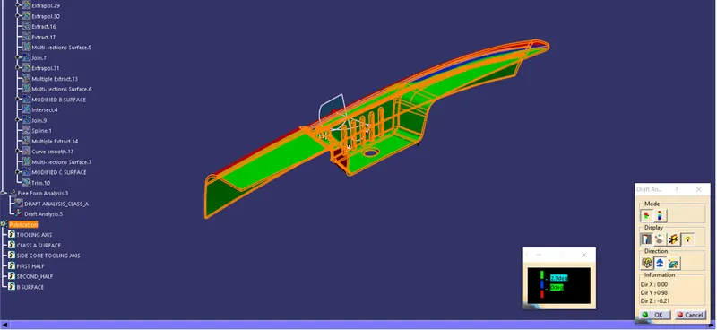
The side core tooling axis created clears the draft analysis of the surface which wasn't achieved using the main tooling axis.
The above image shows the side core axis clearing the front face.
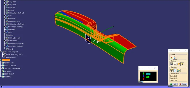
The above image shows the side core axis clearing the backside undercut.
Thus two side cores are dependent on the side core axis.