Week 2:- BiW Fixture Basics Challenge
- What is the process of project execution activity?
Project activities are the various practices that are involved in the project from the beginning to the end of the project. The various steps of project activity are as follows.
1.RFQ received
It is the first stage of the project. RFQ stands for request for quotation. The customer specifies the requirement and specification of the project in the form of data or a document. The technical offer, commercial offer and the timeline for the completion of the project are also specified by the customer.
2.1st Spec discussion meeting
After receiving the RFQ from the customer, the documents regarding the technical offer, commercial offer, and timeline are prepared. The timeline includes the time required for design, Simulation, manufacturing till the installation of the product to the customer.
3.Offer submission
The prepared document is then submitted to the customer to work on it, to check whether the requirements are met and the time period mentioned is acceptable and feasible for them.
4.LOI/PO receipt
The documents which are submitted will be studied by the customer. The customer also gets documents from other firms, compares them, and select the best offer that would suit their requirement. Once the customer chooses the best offer the purchase order is generated and the work will be started. Meanwhile, the project team does a little work on the project so that they would adhere to the timeline once the PO is given to them.
5.Schedule Preparation
After the PO is received the project officially starts and the schedule is prepared for the various stages of the project to complete the project within the specified timeline. All the activities including the time before PO receipt is added to the schedule. The time is segregated and deadlines are set for every stage to make sure the whole project gets completed within the deadline specified by the customer.
6.BOM
BOM stands for Bill of material which is prepared for the project for the parts that are required for the project like motors, cylinders, etc.
7.Design Concept Preparation.
The data is received like the 3d data from the car panel and 2d drawings from the customer along with the LOI/PO regarding the requirements. Using this data, the design concepts are prepared to fulfill the customer's needs.
8.Customer approval
After the design concept is prepared from the data provided by the customer. The designed concept is sent to the customer for approval. The customer checks whether the submitted design adheres with the technical offer or not. If it is satisfied then the customer approves the design and if not few changes will be made in the design and later will be approved.
9.Detailing and Drawing Release
Once the final approval is given by the customer after making the required changes, the design drawings are released with all the necessary details like dimensions, tolerances, etc.
10.Manufacturing / BOM Ordering
The released drawing is submitted to the manufacturing team and they start manufacturing the parts like the riser, Mylar, etc, and the parts like the motors, sensor, and cylinders are ordered.
11.Mechanical /Electrical Assembly
The ordered parts undergo prior quality control checks and also they are checked for the required specifications. Once the quality check is done the mechanical and electrical parts are assembled as per the design.
12.Quality Inspection
After the assembly again the quality inspection is done to check whether the dimensions are as per the design data, the coordinates, and accuracy. The relative dimensions between the two pins are also checked. CMM is used for inspection purposes.
13.Internal Trial and Testing
Once the assembly is quality approved, internal trial and testing are done where the assembly is put into the fixture and checked for the position of the pins and whether the clamping is proper or not. Operations like welding, Loading, and unloading are also tested during the trial.
14.Online Trial
In the Online trial, everything is done using the control panel in an automated mode and checked whether the sequence of operation is as per the specification. The customer approves the part after the online trial.
15.Packaging and Dispatch
Once the customer approves after the online trial. He asks the team to send the part for installation. The fixture is packed and proper packaging is ensured so that there is damage during the transportation of the fixture both functionally and aesthetically. After the packaging is done the fixture is dispatched to the customer.
16.Installation as per layout
A layout will be designed at a very initial level to show the position of mounting of the robot, mounting of fixtures. This layout is designed as per the functional requirements of the customer.
17.Trials and Training at the customer.
After the installation, there will be a trial at the customer's place. Production trials are to see whether the number of units processed by the fixture is meeting the requirement or not and whether the quality standards are met or not. Then training is given to the engineers, operators at the customer end regarding the controls, the operating sequence.
18.Buyoff meeting and Final Handover.
The customer will check all the requirements and whether the listed specification is available or not. Customers will sometimes give few additions and finally if the customer is satisfied with the part, the project is handed over to the customer.
2. What are the types of joining processes?
Joining comprises a large number of processes used to assemble individual parts into a larger, more complex component or assembly. The individual parts of a component meet at the joints. Joints transmit or distribute forces generated during service from one part to the other parts of the assembly.
Joining processes include welding, brazing, soldering, mechanical fastening, and adhesive bonding.
Mechanical fastening can be used to provide either temporary or permanent joints, while adhesive bonding, welding, brazing, and soldering processes are mainly used to provide permanent joints.
Mechanical fastening and adhesive bonding usually do not cause metallurgical reactions.
Consequently, these methods are often preferred when joining dissimilar combinations of materials and for joining polymer-matrix composites that are sensitive to extreme heat.
Types of Joining Processes
- Metallurgical Joining
- Mechanical Joining
- Chemical Joining
Metallurgical Joining are classified into
- Welding
- Brazing
- Soldering
WELDING
In the welding process, two or more parts are heated and melted or forced together, causing the joined parts to function as one. In some welding methods, a filler material is added to make the merging of the materials easier. Welding processes usually divided into three main groups, solid-state and liquid state welding, but there is a third type namely solid/liquid state.
Solid-state Welding Processes:
In solid-state welding such as friction welding, forge welding, explosion welding, etc. The surfaces to be joined are brought into close proximity by heating the surfaces without causing melting and applying normal pressure and providing relative motion between the two surfaces, after stop the motion is applying high pressure without heating. In these processes the materials remain in solid-state and welding is achieved through the application of heat and pressure or high pressure only.
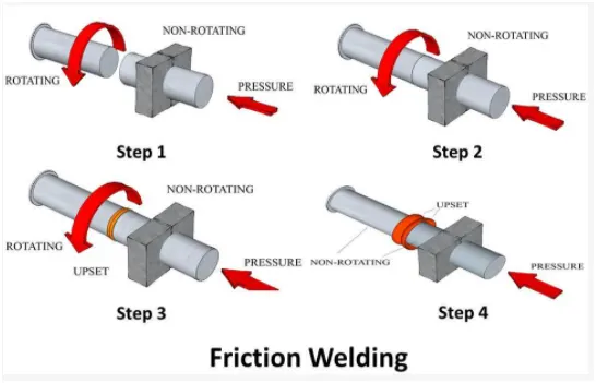
Liquid State (Fusion) Welding Processes:
Arc welding, resistance welding, oxy-fuel gas welding, etc. There are two inherent problems with fusion welding, the effect of localized heating and rapid cooling on the microstructure of the parent metals and the effect of residual stresses developed in the parent metals due to restrained expansion or contraction.
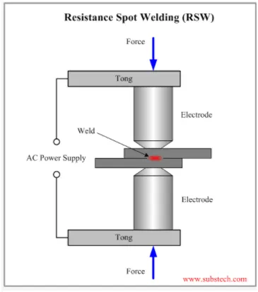
Solid / Liquid State Welding:
In this state low temperature joining methods are used when the metal to be joined cannot withstand high temperature, or complex sections are to be joined, or dissimilar metals are to be joined, or weldability of material is poor. Also in these methods, the gap between the metal pieces to be joined is filled with molten filler material after heating the base metal. The melting point of filler material is much lower than base metals. The bonding is not due to the melting of parent metal. The filler material is drawn into the gap between the metal pieces to be joined by capillary action and the bond formation is started when the molten filler metal comes to contact with the solid surface as in solid-state welding. The nature of the bond formed is much complex here, there is some inter-solubility between filler and base metals to produce the resulting alloy. This inter-diffusion at the base metal surface and resulting alloy have a strength that is very close to that of the base metal.
BRAZING
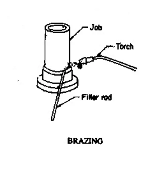
During the brazing process, a filler metal is melted and distributed in between multiple solid metal components after they have been heated to the proper temperature. The filler metal must have a melting point that is above 840 degrees Fahrenheit but below the melting point of the base metals and the metal must also have high fluidity and wettability. No melting of the base metals occurs during brazing. Strong, uniform, leak-proof joints can be made rapidly, inexpensively, and even simultaneously. Joints that are inaccessible and parts that may not be joinable at all by other methods can often be joined by brazing. Automation is also simplified by the fact that heat can be applied to joints by many means, including torches, furnaces, induction coils, electrical resistance, and dipping. Several joints in one assembly often can be produced in one multiple-braze operation during one heating cycle, further enhancing production automation.
SOLDERING
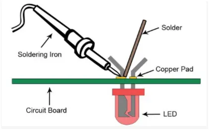
Soldering is the joining process that is similar to brazing except that it is performed at a much lower temperature as compared to brazing. It is a low-temperature joining process. It is performed at temperatures below 840F for joining. The base metal does not melt during the soldering process.
Common soldering materials include Tin-Lead, lead-silver, and silver cadmium. The solder is usually distributed between the properly fitted surface of the joint by capillary action.
2.Mechanical Joining
Mechanical Joining is a process for joining parts through mechanical methods, which often involve threaded holes. Joining parts using screws or nuts and bolts are common examples of mechanical joining. The threaded holes employed for mechanical joining are vulnerable to fractures. In ductile materials, the fracture can come from fatigue, while in brittle materials, the fracture can simply result from mechanical overloading. Thus, mechanical joints must be designed with fatigue failure and brittle fracture in mind. Another issue to be considered when designing mechanical joints is galvanic corrosion, which is a type of corrosion that affects different types of metals that are in contact with each other.
Riveting
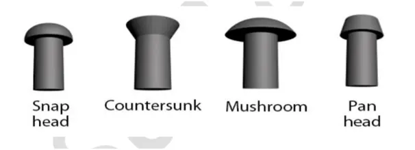
Rivets are used to join two sheets or plates of metal together. There are four main types of rivets: snap head, mushroom, pan head, countersunk, and the operation with join by rivets including;
- The rivet is placed into a tool called a dolly that is held in a vice.
- The plates are then placed over the rivet.
- The rivet set is then placed over the rivet and pressed down to ensure that there are no gaps between the sheets/plates of metal.
- The rivet set is tapped with a ball pein hammer.
This closes any gaps and starts to form the rivet joint. The ball pein hammer is then reversed to form the head of the rivet. The final stage is using a rivet snap to form a similarly shaped dome on both sides of the joint.
Hemming
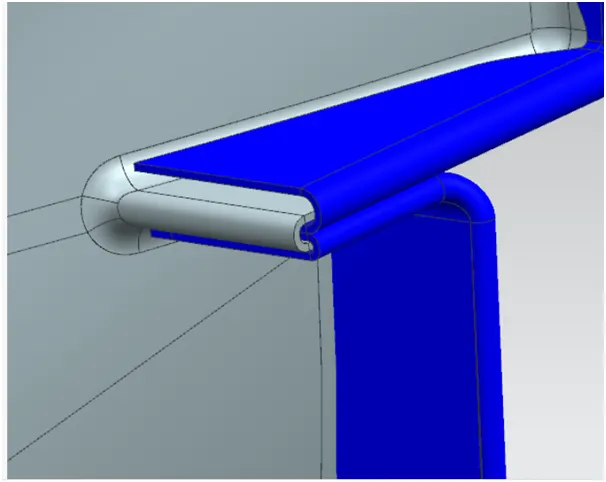
Hemming is the folding of the edges of the sheet metal to create round and safe edges.
Hemming is generally used to wrap the outer panels and the inner panels of the BIW parts.
Bolting
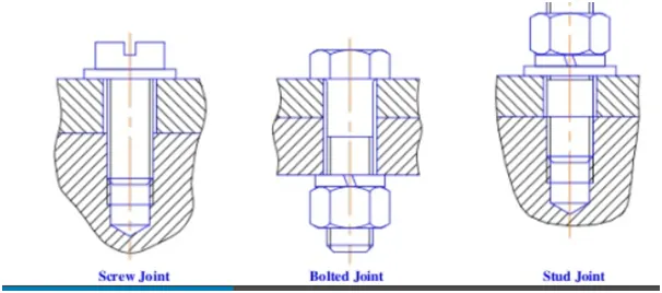
In this joining process, the metallic parts are joined together by the means of bolts, screws, and nuts.
This process is widely used in the assembly of parts that are to be joined temporarily or joints that require periodic maintenance.
3.Chemical Joining
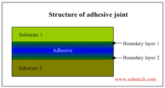
Adhesive bonding is a process of joining materials in which an adhesive is placed between the faying surfaces of the components called adherents. Adhesive bonding is similar to soldering and brazing of metals in that a metallurgical bond does not take place through the surfaces being joined may be heated but they are not melted. An adhesive may be cement, glue, mucilage (sticky liquids from plants), or a paste. Though natural adhesives both of organic and inorganic origins are available, synthetic organic polymers are usually employed to adhesive bond metals. An adhesive in the form of a liquid or a tacky solid is placed between the surfaces, to be joined, which are then mated and heat or pressure or both are applied to accomplish the joint. The advantages of adhesive bonding include bonding of dissimilar materials at low processing temperatures of 65 to 175°C. Thin gauge materials can be bonded effectively. Adhesive joints can provide thermal and electrical insulations with smooth surface appearance resulting in uniform stress distribution. Good vibration and sound damping can be achieved by adhesive bonding. Adhesive bonds result in significant weight saving and simplification of design.
3. What are Resistance Welding & its application in the automotive sector?
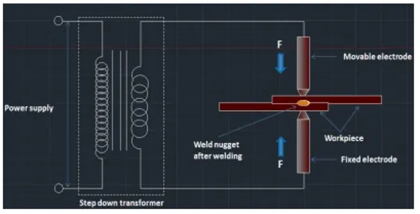
- Resistance welding is a fusion welding process in which coalescence of metals is produced at the faying surfaces by the heat generated at the joint by the resistance of the work to the flow of electricity.
- Force is applied before, during, and after the application of current to prevent arcing at the workpiece.
- Melting occurs at the faying surfaces during welding.
The working principle of resistance welding is the generation of heat because of electric resistance. The resistance welding such as seam, spot, protection works on the same principle. Whenever the current flows through electric resistance, then heat will be generated. The same working principle can be used within the electric coil. The generated heat will depend on the material’s resistance, applied current, conditions of a surface applied, and the current time period.
The following metals may be welded by Resistance Welding:
- Low carbon steels - the widest application of Resistance Welding
- Aluminum alloys
- Medium carbon steels, high carbon steels, and Alloy steels (may be welded, but the weld is brittle)
Advantages of Resistance Welding:
- High welding rates
- Low fumes
- Cost-effectiveness
- Easy automation
- No filler materials are required
- Low distortions
Disadvantages of Resistance Welding:
- High equipment cost
- Low strength in case of discontinuous welds
- The thickness of welded sheets is limited - up to 1/4” (6 mm)
Types of Resistance Welding
- Spot Welding.
- Seam Welding.
- Projection Welding
Spot Welding
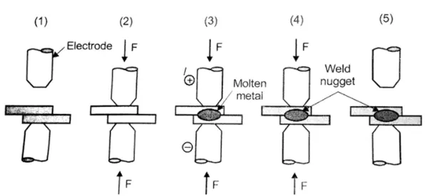
Spot welding is the simplest type of welding where the work portions are held jointly below the force of the anvil face. The copper (Cu) electrodes will make contact with the work portion & the flow of current through it. The work portion material applies a few resistances within the current flow which will cause limited heat production. The resistance is high at the edge surfaces because of the air gap. The current begins to supply through it, then it will reduce the edge surface. The current supply & the time must be enough for the correct dissolving of edge faces. Now the flow of current will be stopped however the force applied with the electrode continued for a second, whereas the weld is quickly cooled. Later, the electrodes eliminate as well as get in touch with new spots to create a circular piece. The piece size mainly depends on electrode size (4-7 mm).
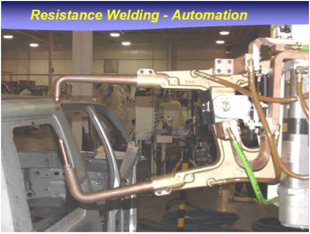
Application: Used in the automotive assembly line to join the various BIW panels together.
Seam Welding
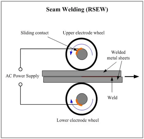
This type of welding is also known as continuous spot welding where a roller form electrode can be utilized to supply current throughout work parts. Initially, the roller electrodes are getting in touch with the work part. High current can be supplied through these electrode rollers to melt the edge surfaces & shape a weld joint. At present, the electrode rollers will begin rolling on work plates to make a permanent weld joint. The weld timing & electrode movement can be controlled to guarantee that the weld overlap & work part doesn’t acquire too warm. The speed of the welding can be about 60 per min within seam welding, which is used to make airtight joints.
Application: Used in manufacturing of Closure components used in Automobile which needs to be airtight eg: Fuel tank
Projection Welding
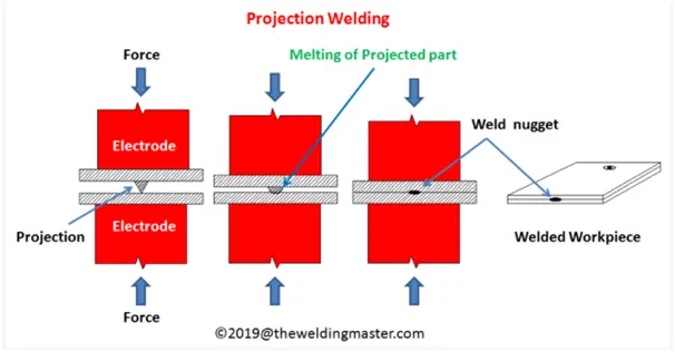
Projection welding is similar to spot welding apart from a dimple that can be generated on work parts at the place wherever weld is preferred. At present the work parts held among electrode as well as a huge quantity of current flow through it. A little quantity of pressure can be applied throughout the electrode on welding shields. The flow of current throughout the dimple dissolves it & the force reasons the dimple level & shape a weld.
Application:
Used for mechanical Fixing of Autobody Structures Eg: Weldnut
4. What is fusion welding & types of fusion welding with their application in the automotive sector?
The fusion welding process involved localized melting and solidification and is normally used when joining similar material combinations or materials belonging to the same family.
In infusion welding, the weld can be made by simply melting the edges of the two workpieces and allowing them to fuse together on cooling. This type of weld is referred to as an autogenous weld.
The other method is to add extra material during the welding process through the melting of a filler wire or electrode during the welding process. In both cases, the welded area will have a microstructure and properties that are different from the parent metal.
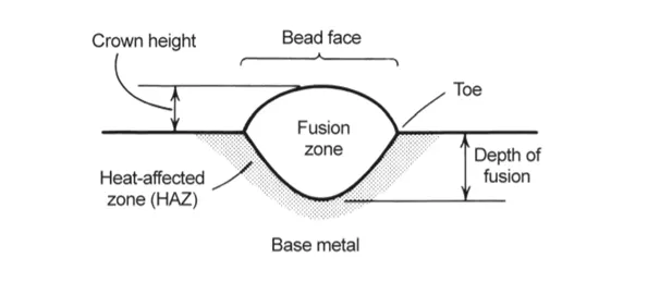
The three predominant zones in a fusion weld are the fusion zone, a heat-affected zone (HAZ), and the base metal as shown below.
To maintain tolerances, distortion due to localized heating and cooling must be prevented or controlled by the use of jigs and fixtures.
Fusion welding is further divided into
- Gas Welding
- Arc Welding
- Thermit welding
GAS WELDING
A type of chemical-based fusion welding, oxyfuel welding involves the use of a flame to heat and join surfaces, with oxygen as the fuel source. Fire, of course, needs oxygen, which is the basis on which oxyfuel welding works. The oxygen fuels the fire to create a hot flame in excess of 4,500 degrees Fahrenheit. Oxyfuel welding typically uses a combination of oxygen and flammable gas to create a hot flame to join objects.
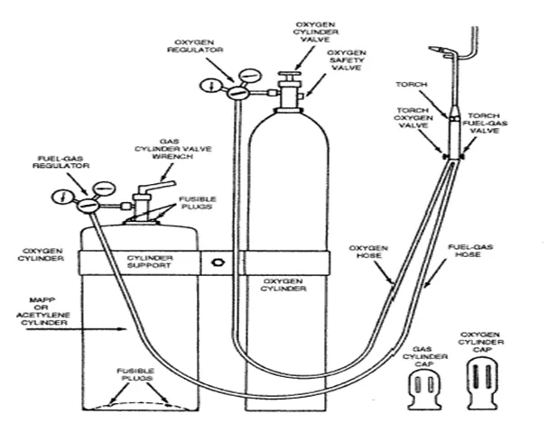
Oxy-acetylene welding uses a high-heat, high-temperature flame that is produced by burning a fuel gas (most commonly acetylene) mixed with pure oxygen. The base material is melted with the filler rod using a flame from the combination of oxy-fuel gas through the tip of the welding torch.
The fuel gas and oxygen gas are stored in pressurized steel cylinders. Regulators in the cylinder reduce gas pressure.
Gas flows through flexible hoses, with the welder controlling the flow via the torch. The filler rod is then melted with the base material. However, melting two pieces of metals is also possible without the need for the filler rod.
It is used in automotive industries to weld parts of the frame and chassis.
ARC WELDING
The most popular type of fusion welding is arc welding. Arc welding lives up to its namesake by relying on an electric arc to join two or more objects. With electric arcs measuring up to 6,000 degrees Fahrenheit, this fusion welding process is highly capable of melting even the toughest metals. Furthermore, arc welding can be performed underwater, making it an ideal solution for offshore welding projects.
Metal Inert Gas welding(MIG)
MIG (Metal Inert Gas) welding is a welding process in which an electric arc forms between a consumable wire electrode and the workpiece. This process uses inert gases or gas mixtures as the shielding gas. Argon and helium are typically used for the MIG welding of non-ferrous metals such as aluminum.
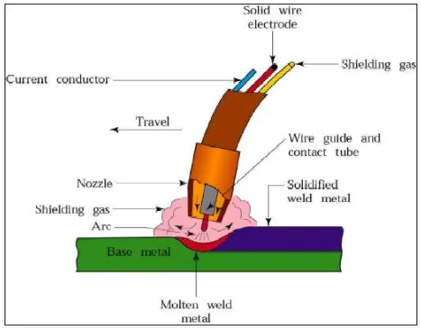
MIG welding allows for the fast production of high-quality welds and, due to a lack of flux being used, there is no chance of slag being trapped in the weld metal. The disadvantages of MIG welding are that it cannot be performed in a vertical or overhead position, due to the high heat and fluid nature of the weld pool. Also, the equipment used by a MIG welder can be complex.
MIG is used in the fabrication of sheet metal and also can be used for deep groove welding.
Shielded Metal Arc Welding
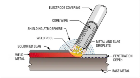
Shielded Metal Arc Welding, otherwise known as manual metal arc welding or flux shielded arc welding, is a process that uses a flux-coated electrode to form the weld. As electricity passes through the electrode, the flux forms a gas, which shields the electric arc in the space between the electrode and the metal being welded, preventing contamination from atmospheric gasses in the weld. This process is fairly simple and doesn’t require much in the way of specialized equipment.
Tungsten Inert Gas Welding(TIG)
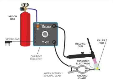
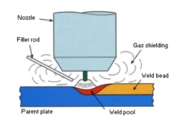
In the TIG welding process, the arc is formed between a pointed tungsten electrode and the workpiece in an inert atmosphere of argon or helium. The small intense arc provided by the pointed electrode is ideal for high quality and precision welding. Because the electrode is not consumed during welding, the TIG welder does not have to balance the heat input from the arc as the metal is deposited from the melting electrode. When filler metal is required, it must be added separately to the weld pool.
TIG welding is applied in all industrial sectors but is especially suitable for high-quality welding. In manual welding, the relatively small arc is ideal for thin sheet material or controlled penetration (in the root run of pipe welds). Because deposition rate can be quite low (using a separate filler rod) MMA or MIG may be preferable for thicker material and for fill passes in thick-wall pipe welds.
Plasma Arc Welding
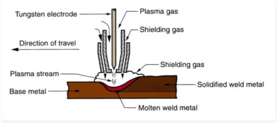
This process uses an electric arc created between an electrode and the torch nozzle. The electric arc ionizes the gas in the chamber creating plasma. It is then forced through a fine boring copper nozzle that directs the arc to the workpiece, allowing the plasma arc to be separated from the shielding gas.
They are usually used in aerospace applications and used for melting nickel alloys.
5.What is the 3-2-1 principle?
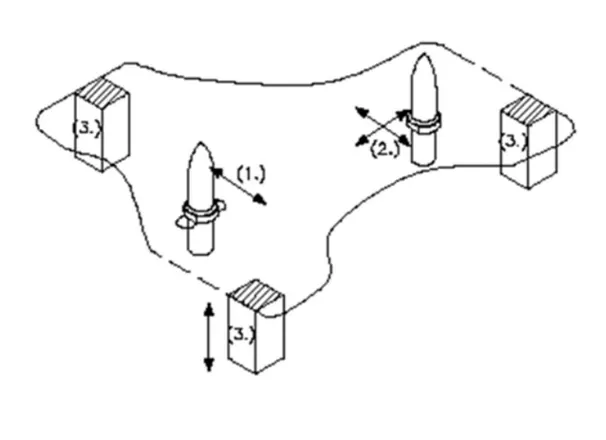
The 3-2-1 method is a work-holding principle where three pins are located on the 1st principle plane, i.e. either XY, YZ, ZX. And two pins are located on the 2nd plane which is perpendicular to the 1st plane, and at last one pin on the plane which is mutually perpendicular to the 1st and 2nd planes. The ultimate goal is to constrain the movement of the workpiece along all three axes.
3.Minimum
From the above figure, We can see three locator blocks positioned at the primary locating surface. These three locators restrict the axial upward and downward movement along with it the two radial movements both clockwise and Anti clockwise are also restricted. So, a total of four radial movements is restricted to the two mutually perpendicular axes.
The three locators, on the whole, have restricted six Degrees of freedom.
2.Round Locating Pin
The pin added in the location of the hole restricts the axial movements of two perpendicular axes (both positive and negative). Thus, restricting Four Degrees of freedom.
1.Round Locating Pin
The round locating pin is added to the slot in order to restrict the remaining radial movement in both clockwise and anti-clockwise. This, therefore, restricts the remaining two degrees of freedom.
Thus, the 3-2-1 principle is used to restrict the 12 degrees of freedom of a part.
6.Define Body coordinate system?
- The body coordinate system is widely used in the automotive industries for drawing body parts, products, and process design.
- A coordinate system is a reference system consisting of a set of points, lines, and surfaces used to define the position of points in space in either two or three dimensions.
- To represent the position of BIW car parts, welding fixture and its unit assemblies with its individual parts (e.g. Mylar(the parts which are in contact with panel)) in 2D drawings, their respective positions are shown with reference to (X=0, Y=0, Z=0)positions. In short, it shows in 2D XY, YZ, or XZ coordinate position of BIW welding fixture parts or assemblies with reference to origin X=0, Y=0, Z=0
- Let us consider a situation if an individual fixture designer starts designing a part or panel on their default axes system then it will be difficult to assembly or position the part with respect to each other. So in order to avoid this all the designer starts designing with respect to car axes system (which is generally at the center of the front axle)
We consider a case where the axes system is from the front end of the car
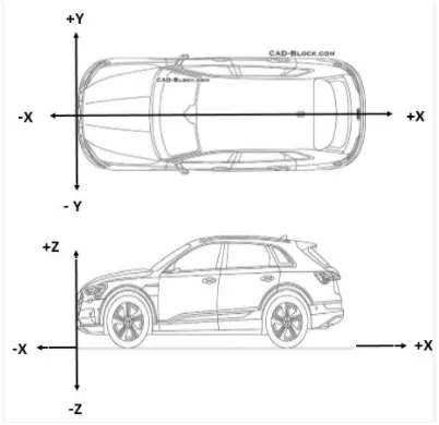
- X – Longitudinal direction [Front ‘o’ Line –FoL]
- Y – Transverse direction [Center ‘o’ Line – CoL]
- Z– Vertical direction [Bottom ‘o’ Line – BoL]
The origin of the body coordinate system OX is defined at the front center of the car and it indicates the length of the car. The origin of the OZ [bottom O Line] is defined at the bottom of the car in the plane where the tire of the vehicle touches the ground and it indicates the height of the car. Finally, the origin of the OY coordinate lies in the center of the car and it indicates the width.
7.Elaborate Body plane system & its essentials
Body planes are reference planes in an automotive car. These planes are used to define the GD&T of all car parts in an automotive domain.
Body planes are three mutually perpendicular imaginary planes. These are generally considered to be present at the driver position or sometimes at the engine location or at the front end of the car
The measurements from the body planes to the body parts are called body line dimensions.
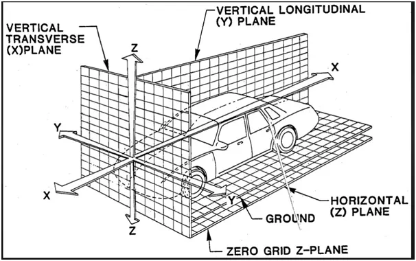
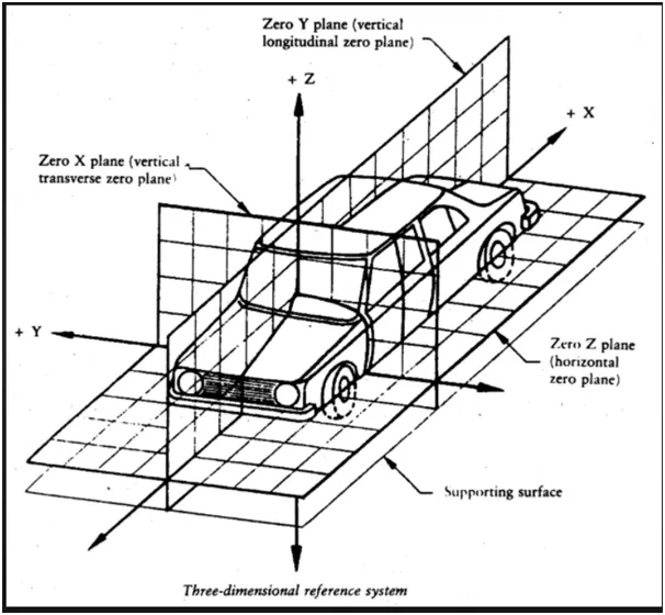
The need of the body planes are as below
- It defines the exact position of each part of the car with respect to a fixed origin.
- It ensures flawless design for assembly.
- It assists in the location of different parts in the vehicle
- It creates a standard system
- It is very helpful in Quality checks.