Week 11 - Final project
AIM
To Develop a Door Trim panel from the given Class-A surface Input considering the OEM standards.
INPUT SURFACE
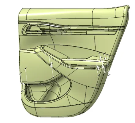
The above image is the given input surface of the door trim panel, the input surface is subdivided into 4 parts and is worked in order to create a tooling axis, Class A surface, Class B surface, and Class C surface along with the engineering features of the Plastics. The manufacturability of the parts is also considered while designing the part.
INTRODUCTION
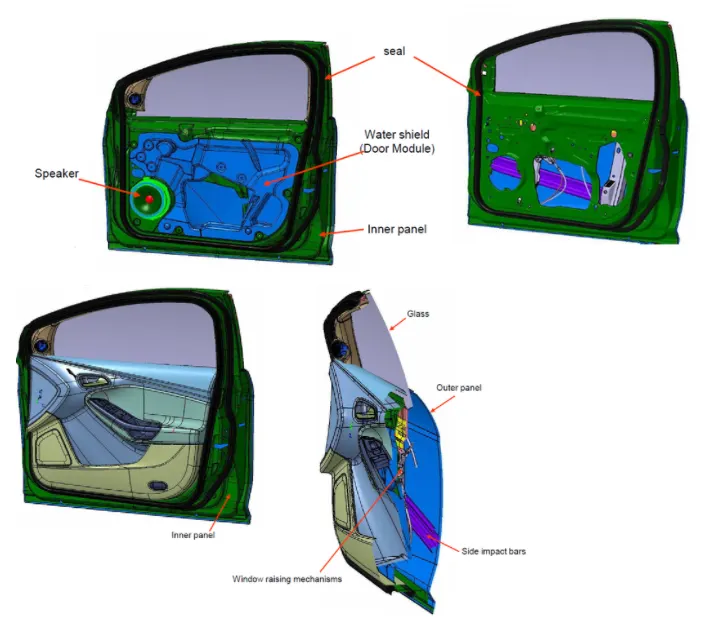
Door Trim is an interior component attached to the inner side of the door. This product does more than merely improve the appearance of the vehicle's interior. Rather, it is a vital module component that creates a more comfortable interior by providing a variety of accouterments and functions.
The trim panel basically covers the inside of your door and connects the various electrical components in your car, including the control panel for the power windows and locks. Over time, moisture, dirt, and debris will get inside the door trim panel and ruin its good condition.
Creation of tooling axis for the given Class-A surface
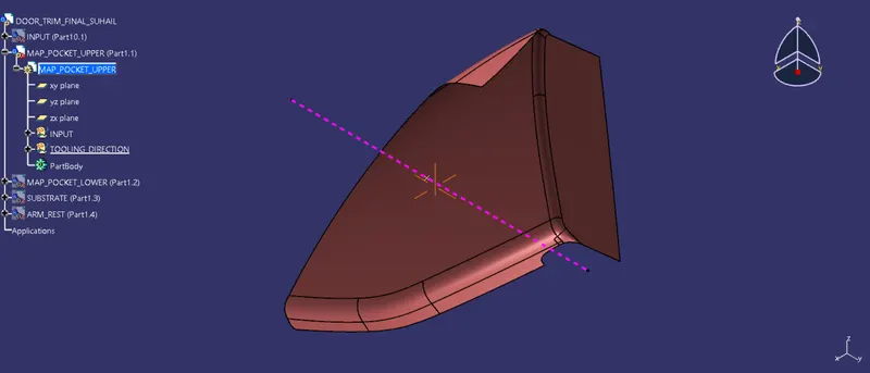
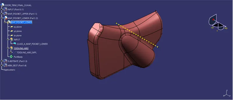
- Tooling Axis direction is the direction in which the core and cavity open.
- The selection of tooling direction depends upon the product and the features of the product.
The tooling direction is selected by visually checking the part and in such a way that there are no additional side cores required for the molding process. This ensures proper clearance of the part after the process.
The upper map pocket, the lower map pocket, and the substrate will have the Natural tooling direction i.e. the compass direction is taken as the tooling direction. The selection of the natural tooling axis will be beneficial while manufacturing the core and cavity.
In this case, the Y-axis is the natural tooling direction.
UPPER MAP POCKET TOOLING DIRECTION
LOWER MAP POCKET TOOLING DIRECTION
SUBSTRATE TOOLING DIRECTION
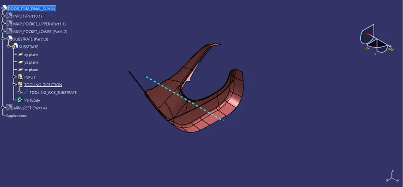
DOOR ARMREST

The Z-axis is considered as the tooling direction for the door armrest surface.
Class B surface and Class C surface Creation.
Class B surface is a surface that is below a certain thickness from the class A surface. The engineering features of the product are on the class B surface while the class A surface is the styling surface.
The Class C surface is the surface used to join class A and the Class B surface.
Creation of Class B surface for all four components.
UPPER MAP POCKET
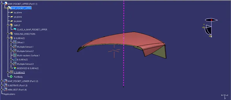
CLASS B SURFACE CREATED FOR THE UPPER MAP POCKET
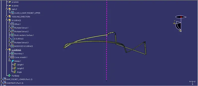
CLASS C SURFACE FOR THE UPPER MAP POCKET
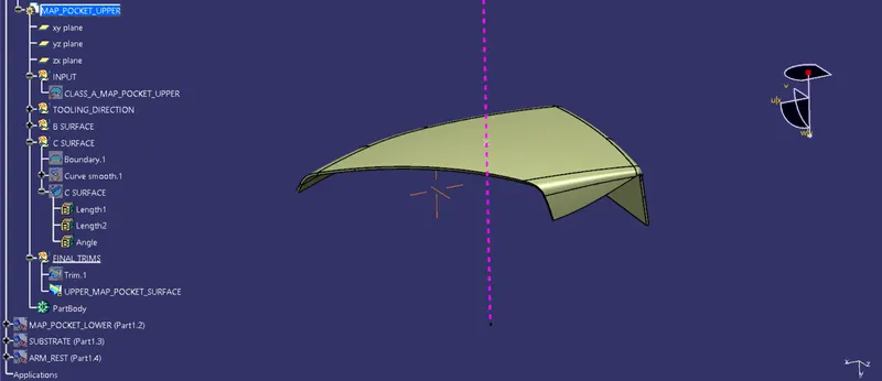
The above image shows the final surface output of the upper map pocket.
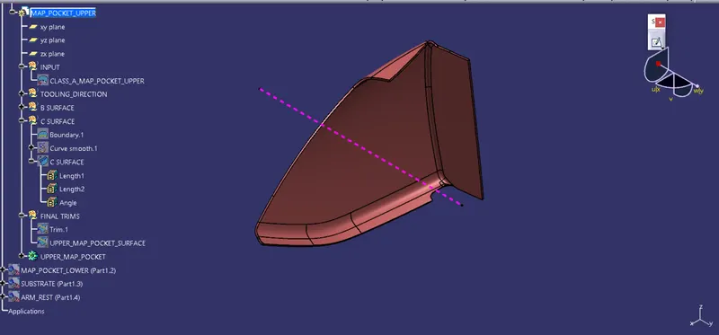
Upper map pocket Final body.
LOWER MAP POCKET
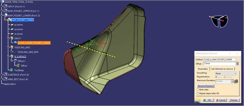
CLASS B SURFACE CREATED FOR THE LOWER MAP POCKET
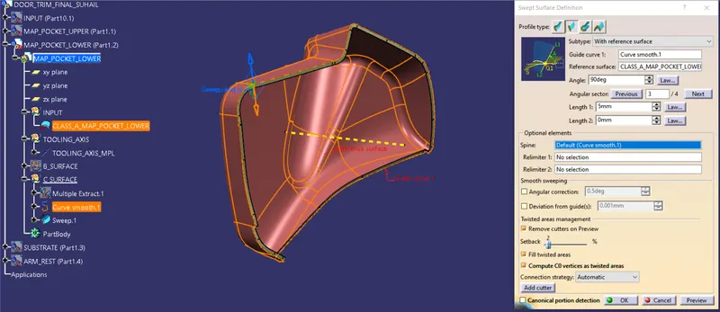
CLASS C SURFACE CREATED FOR THE LOWER MAP POCKET
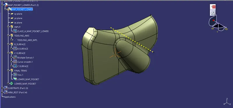
SURFACE OUTPUT OF THE LOWER MAP POCKET
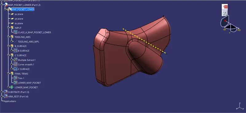
Lower map pocket final body.
SUBSTRATE
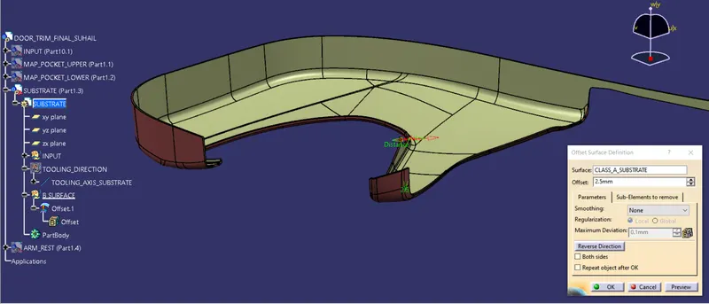
CLASS B SURFACE CREATION FOR THE SUBSTRATE
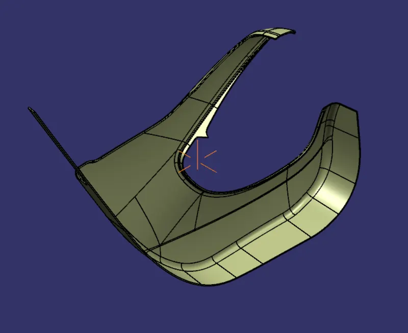
SURFACE OUTPUT OF THE SUBSTRATE
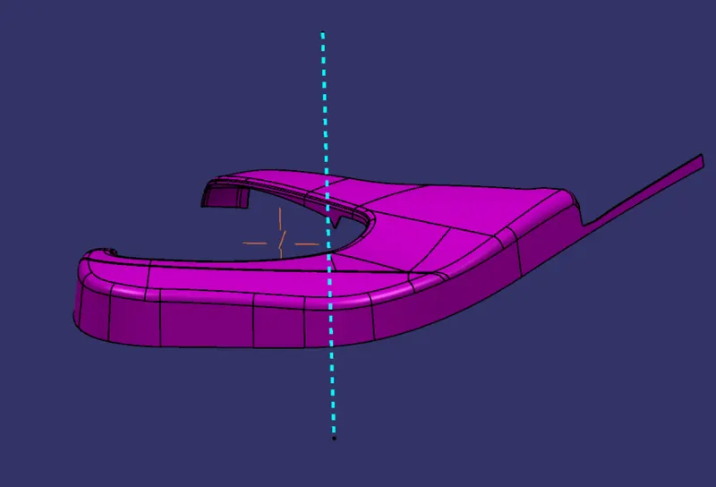
FINAL BODY OF THE SUBSTRATE.
ARMREST
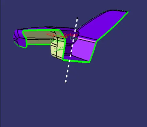
CLASS B SURFACE CREATION OF THE ARMREST
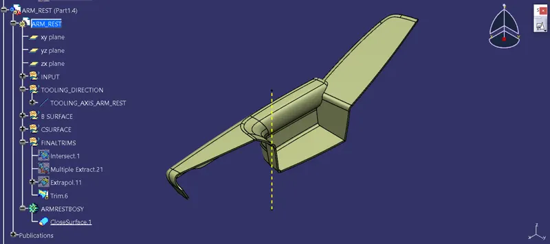
FINAL SURFACE OUTPUT OF THE ARMREST WITH C SURFACE CREATED
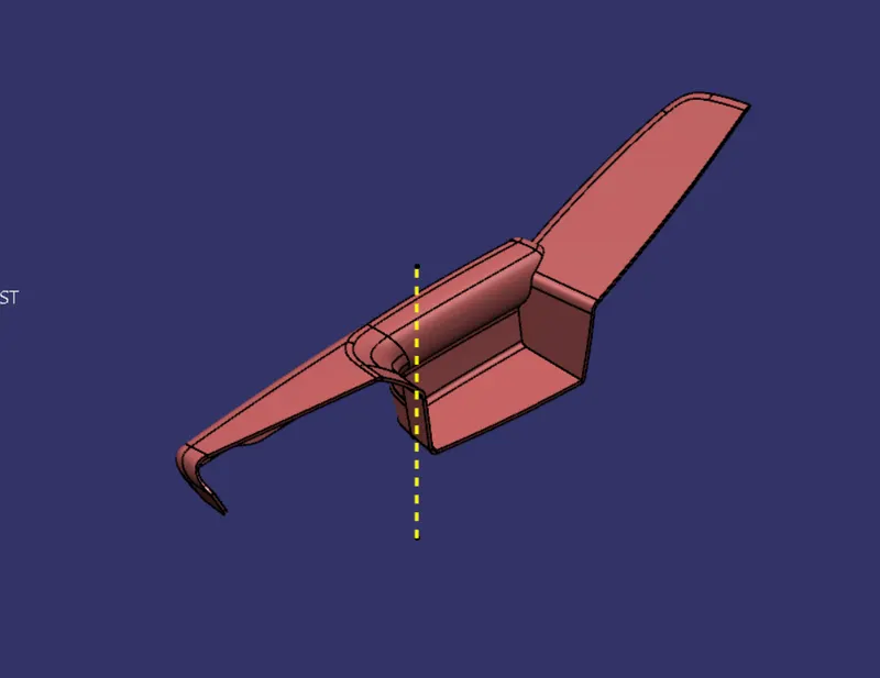
FINAL BODY OF THE ARMREST.
CREATION OF B-SIDE FEATURES FOR THE VARIOUS COMPONENTS OF THE DOOR TRIM PANEL.
Below are the B side features used in the door trim design
- FLANGES
- DOGHOUSE WITH PUSHPIN
- HEAT STAKES
- SCREW BOSS
FLANGES
Flanges are used to attach the components of the door trim panel such as the armrest, Upper and lower map pocket to the main substrate of the door trim panel.
The master sections provide the dimension and location of the flanges.
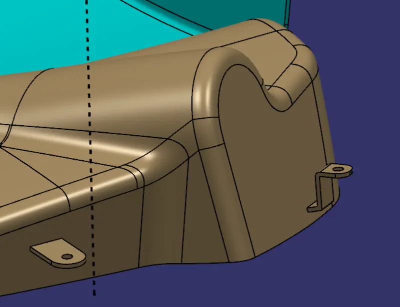
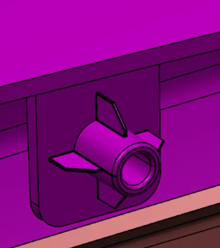
DOGHOUSE WITH PUSHPIN
The dog house is an engineering feature used in the plastic trim design. Dog houses are used as supporting features. Sometimes other engineering features like snaps; locators, etc. are mounded on them to increase their strength.Dog houses are subjected to draft analysis to prevent breakage of the component during ejection from the mold cavity.
DESIGN CONSIDERATION FOR CREATING DOGHOUSE
Wall thickness = 0.70 x Thickness of the plastic material
Fillet on the inner side = 0.25 x Thickness of the plastic material
Fillet on the outer side = 1.25 x Thickness of the plastic material
Fillet on the coring edges = 0.25 x Thickness of the plastic material
Coring thickness = 0.40 x Thickness of the plastic material
Draft angle 2deg to 3deg
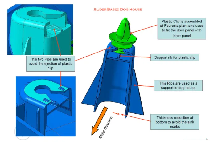
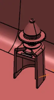
The above image shows the doghouse created on the substrate of the door trim panel with a pushpin Clip.
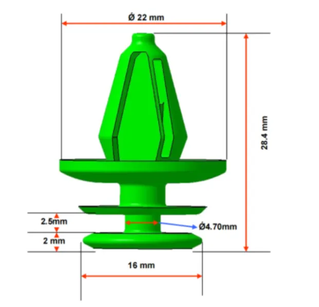
The pushpin clip is used to attach the door trim to the inner panel.
HEAT STAKES
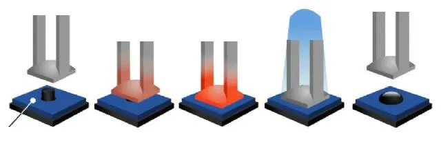
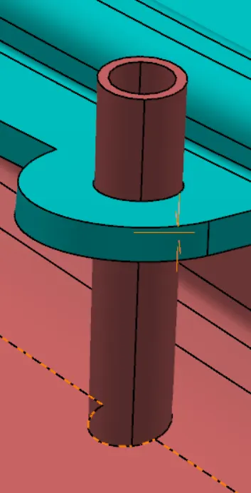
Heat staking also known as thermoplastic staking is the process of joining two dissimilar materials together. In heat staking, we use local heating and cooling to raise the temperature of plastic components and allow plastic reforming to be carried out. This reforming can be used in a wide variety of applications.
Applications range from staking plastic boss for assembly of car door panels to joining PCBs to plastic housings. Benefits of this technique include; no vibration damage, no particulates, the ability to stake metalized coated applications, and the capability to stake in difficult to access or restricted areas.
SCREW BOSS
- Bosses are used to facilitating the registration of mating parts, for attaching fasteners such as screws, or for accepting threaded inserts.
Wall thickness for bosses should be less than 60 percent of the nominal wall to minimize sinking.
However, if the boss is not in a visible area, then the wall thickness can be increased to allow for
increased stresses imposed by self-tapping screws. The diameter of the hole in the boss should be equal to0.7 X diameter of the screw.
The boss radius should be a minimum of 0.25 X Thickness. - Bosses can be strengthened by incorporating gussets at the base or by using connecting ribs attaching to nearby walls.
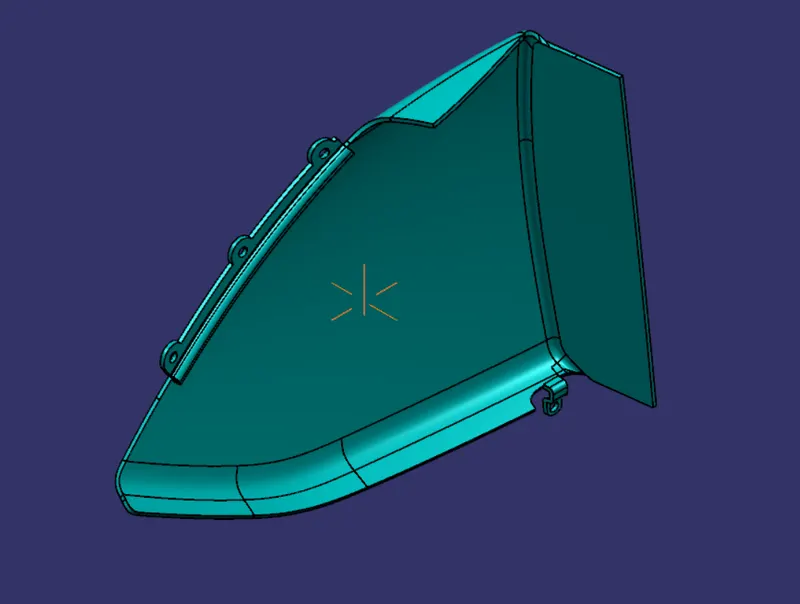
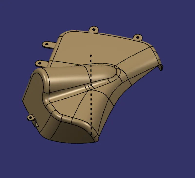
Below are the components of the door trim with the B side features attached
UPPER MAP POCKET
LOWER MAP POCKET
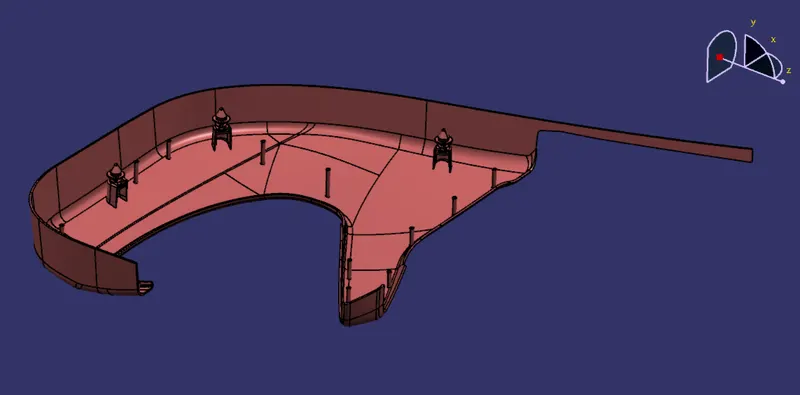
SUBSTRATE
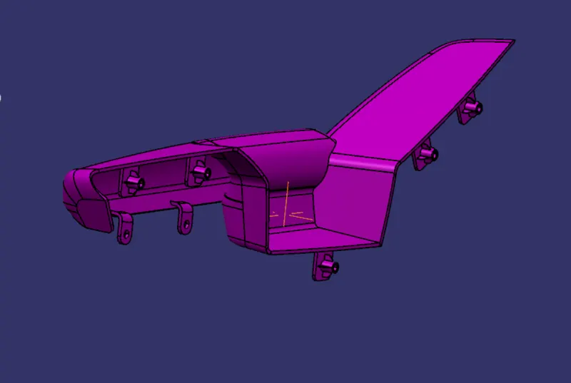
ARMREST
Draft Analysis
When developing parts for plastic injection molding, applying a draft (or a taper) to the faces of the part is critical to improving the moldability of your part. Without it, parts run the risk of poor cosmetic finishes and may bend, break, or warp due to molding stresses caused by the plastic cooling. Equally important, an absence of a draft may prevent parts from ejecting from the mold, damaging not only the parts but possibly the mold itself—a costly and time-consuming detour.
In CATIA the draft analysis can be found by Insert > Analysis> Feature Draft Analysis.
Generally, the nominal draft angle will be 3 degrees.
Draft Analysis for the class A surface.
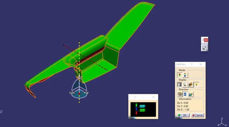
Draft Analysis of the Armrest Class A surface with main tooling axis.
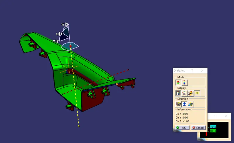
Draft analysis of the Armrest body along the main tooling direction.
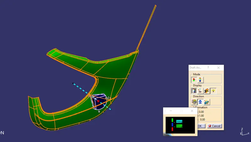
Draft Analysis of the substrate Class A surface.
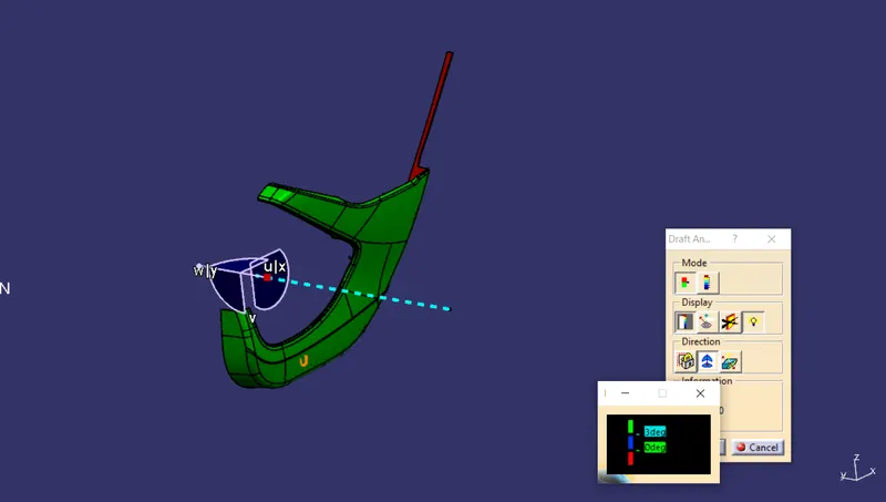
Draft analysis of the substrate body
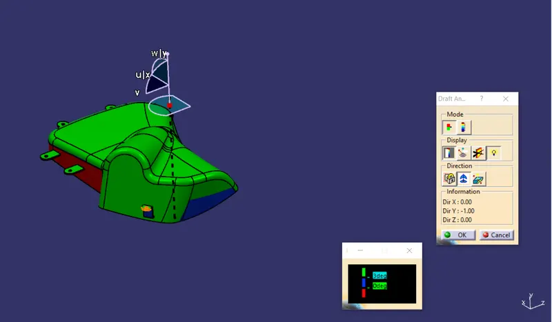
Draft Analysis of the lower map pocket body
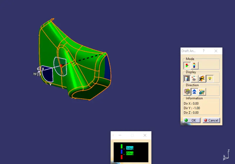
Draft Analysis of the lower map pocket Class A surface
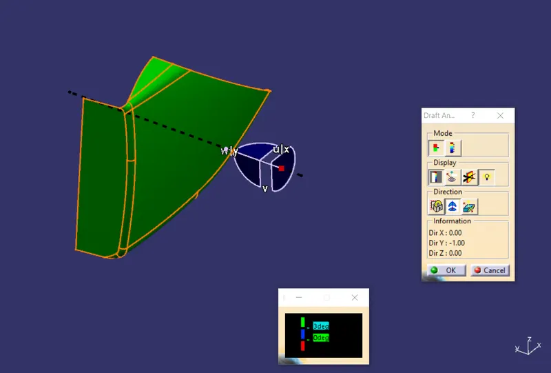
Draft Analysis of the upper map pocket Class A surface.
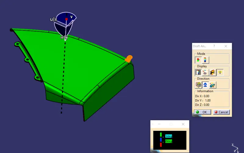
Draft Analysis of the upper map pocket Body.
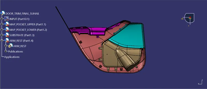
Final Assembly of the Door Trim Panel.
CONCLUSION
Hence, the Door trim panel was developed from the given Class-A surface with the required B side features considering the manufacturability of the component.